
VMware Enterprise PKS Running on VMware vSAN Stretched Cluster
Executive Summary
Business Case
VMware Enterprise PKS enables enterprises to deploy and consume container services with production-grade Kubernetes orchestration. It provides a comprehensive solution for enterprises developing and deploying cloud-native applications.
VMware vSANTM, as a shared storage system for vSphere, provides a uniform management plane for container storage. The deep integration between VMware Enterprise PKS and vSAN means that developers can consume storage as code with freedom by abstracting the complexity of the underlying storage infrastructure. Storage Policy Based Management (SPBM) in vSAN offers users flexibility to define policies on demand in VMware vCenter® and delivers ease of management of storage for containers.
VMware vSAN Stretched Clusters with a Witness Host refers to a deployment where a user sets up a vSAN cluster with 2 active/active sites with an identical number of ESXi hosts distributed evenly between the two sites. The sites are connected via a high bandwidth/low latency link.
Running VMware Enterprise PKS on vSAN Stretched Cluster can provide active-active data protection on both the Kubernetes nodes level and persistent volumes level.
Solution Overview
This solution is a showcase of using VMware vSAN Stretched Cluster as a platform for deploying VMware Enterprise PKS in a vSphere environment. All storage management moves into a single software stack, thus taking advantage of the security, operational simplicity, and cost-effectiveness of vSAN in production environments. Workloads can be easily migrated from bare-metal configurations to a modern, dynamic, and consolidated Hyperconverged Infrastructure (HCI) solution based on vSAN. vSAN is natively integrated with vSphere, and helps to reduce the design and operational burden of a data center.
vSAN Stretched Cluster can provide active-active data protection for all the virtual machines as well as persistent volumes in this reference architecture. This solution focuses on the architecture of running VMware Enterprise PKS on vSAN Stretched Cluster.
The reference architecture covers the following testing scenarios:
- Demonstrate the overall architecture and configuration details
- Demonstrate the NSX-T™ networking architecture
- Deploy Kubernetes clusters using VMware Enterprise PKS management plane in a vSphere and vSAN Stretched Cluster
- Showcase the resiliency and availability testing results
This solution paper is successive and complementary of the previous solution papers around VMware Enterprise PKS: VMware Enterprise PKS on VMware vSAN and VMware® Enterprise PKS with Multiple Availability Zones on VMware vSAN. Some basic configurations and concepts can be found in the two previous paper while this paper is focused on the configuration and test on vSAN Stretched Cluster.
Audience
This paper is intended for cloud-native application administrators and storage architects involved in planning, designing, or administering of VMware Enterprise PKS on vSAN Stretched Cluster.
Technology Overview
Overview
This section provides an overview of the technologies used in this solution. The versions depicted in the table are the minimum required version of each product for running this solution.
| Product | Minimum Required Version |
|---|---|
|
VMware vSphere® 6.7 |
6.7 Update 3 |
|
VMware vSAN |
6.7 Update 3 |
|
NSX-T Datacenter |
2.5.1 |
|
Pivotal Operations Manager (Ops Manager) |
2.8.5 |
|
VMware Enterprise PKS |
1.7.0 |
VMware vSphere 6.7 Update 3
VMware vSphere 6.7 is the infrastructure for next-generation applications. It provides a powerful, flexible, and secure foundation for business agility that accelerates the digital transformation to cloud computing and promotes success in the digital economy.
vSphere 6.7 supports both existing and next-generation applications through its:
- Simplified customer experience for automation and management at scale
- Comprehensive built-in security for protecting data, infrastructure, and access
- Universal application platform for running any application anywhere
With vSphere 6.7, customers can run, manage, connect, and secure their applications in a common operating environment, across clouds and devices.
VMware vSAN 6.7 Update 3
VMware NSX Data Center is the network virtualization and security platform that enables the virtual cloud network, which connects and protects applications new and existing, across data centers and clouds.
VMware vSAN is the industry-leading software powering VMware’s software defined storage and HCI solution. vSAN helps customers evolve their data center without risk, control IT costs and scale to tomorrow’s business needs. vSAN, native to the market-leading hypervisor, delivers flash-optimized, secure storage for all your critical vSphere workloads, and is built on industry-standard x86 servers and components that help lower total cost of ownership (TCO) in comparison to traditional storage. It delivers the agility to easily scale IT and offers the industry’s leading native HCI encryption.
In the vSAN 6.7 U3 release, it provides performance improvements and availability SLAs on all-flash configurations with deduplication enabled. Latency sensitive applications have better performance in terms of predictable I/O latencies and increased sequential I/O throughput. Rebuild times on disk and node failures are shorter, which provides better availability SLAs. The 6.7 U3 release also support cloud native storage that provides comprehensive data management for stateful applications. With Cloud Native Storage, vSphere persistent storage integrates with Kubernetes.
vSAN simplifies day-1 and day-2 operations, and customers can quickly deploy and extend cloud infrastructure and minimize maintenance disruptions. Stateful containers orchestrated by Kubernetes can leverage storage exposed by vSphere (vSAN, VMFS, NFS) while using standard Kubernetes volume, persistent volume, and dynamic provisioning primitives.
VMware NSX-T Data Center
VMware NSX Data Center is the network virtualization and security platform that enables the virtual cloud network, which connects and protects applications new and existing, across data centers and clouds.
NSX-T Data Center is focused on emerging application frameworks and architectures that have heterogeneous endpoints and technology stacks. In addition to vSphere hypervisors, these environments include other hypervisors such as KVM, containers, and bare metal.
NSX-T Data Center is designed for management, operations, and consumption by development organizations. NSX-T Data Center allows IT and development teams to choose the technologies best suited for their applications.
See the NSX-T Data Center document for more information.
Pivotal Operations Manager (Ops Manager) 2.8.0
Ops Manager for Pivotal Platform provides a set of APIs and a graphical interface to manage the deployment and upgrade of Pivotal Platform components. Use Ops Manager to administer Pivotal Application Service (PAS), VMware Enterprise PKS, data services, and partner products.
VMware Enterprise PKS 1.7
VMware Enterprise PKS is a purpose-built container solution to operationalize Kubernetes for multi-cloud enterprises and service providers. It significantly simplifies the deployment and management of Kubernetes clusters with day 1 and day 2 operations support. With hardened production-grade capabilities, VMware Enterprise PKS takes care of your container deployments from the application layer all the way to the infrastructure layer.
VMware Enterprise PKS is built in with critical production capabilities such as high availability, autoscaling, health-checks, as well as self-healing and rolling upgrades for Kubernetes clusters. With constant compatibility to Google Kubernetes Engine (GKE), VMware Enterprise PKS provides the latest stable Kubernetes release so developers have the latest features and tools available to them. It also integrates with VMware NSX-T for advanced container networking including micro-segmentation, ingress controller, load balancing and security policy. Through an integrated private container registry, VMware Enterprise PKS secures container images via built-in vulnerability scanning, image signing and auditing.
VMware Enterprise PKS exposes Kubernetes in its native form without adding any layers of abstraction or proprietary extensions, which enables developers use the native Kubernetes CLI that they are most familiar with. VMware Enterprise PKS can be easily deployed and operationalized via Pivotal Operations Manager, which allows a common operating model to deploy VMware Enterprise PKS across multiple IaaS abstractions like vSphere, Google Cloud Platform (GCP), and Amazon Web Services (AWS) EC2.
Solution Configuration
This section introduces the resources and configurations:
- Solution architecture
- Network architecture
- Pivotal Operations Manager configuration
- vSphere cluster configuration
Solution Architecture
There are two architectures descripted in this reference architecture. The first architecture separates Management, NSX Edge and Compute clusters, which can lead to better performance. The second architecture collapses Management, NSX Edge and Compute clusters into one cluster to reduce the minimum number of required physical hosts to six.
Architecture 1:
As depicted in Figure 1, there were 3 separate stretched vSphere/vSAN clusters in the architecture: one management cluster, one edge cluster and one compute cluster.
There were 3 sites in the architecture: site 1 and site 2 were for data placement, and site3 was for vSAN witness appliance.
Each one of the three clusters consisted of at least six ESXi hosts. They were evenly distributed into 2 data sites. So for each cluster, there were at least 3 ESXi hosts in each data site.
- Management Cluster
The Management Cluster contains the following virtual machines:
- Management vCenter: The vCenter that manages the Management Cluster itself.
- Edge and Compute vCenter: The vCenter that manages both the Edge Cluster and the Compute Cluster.
- NSX-T managers: NSX-T Manager 1 and 2 are located in site 1. NSX-T Manager 3 is located in site 2. This is controlled by vSphere DRS VM/Host affinity rules. For detailed NSX-T installation guide, see NSX-T documentation.
Specifically, for VMware Enterprise PKS deployment, we installed VMware vRealize® Operations Management Pack for Container Monitoring, VMware vRealize Operations Management Pack for NSX-T and VMware vRealize Log Insight with NSX-T Content Pack in vRealize Operations and vRealize Log insight in the management cluster for VMware Enterprise PKS monitoring and analyzing. They were shown as vRealize Suite in the figure.
- Edge Cluster
The Edge Cluster is used for hosting NSX-T edge virtual machines only. A dedicated Edge Cluster can ensure high performance of NSX-T edge gateways. In the example, NSX-T Edge-1 and NSX-T Edge-3 ‘must’ be located in site 1. NSX-T Edge-2 and NSX-T Edge-4 ‘must’ be located in site 2. This is controlled by vSphere DRS VM/Host affinity rule with the Must run on hosts in group option.
NSX-T Edge-1 and NSX-T Edge-2 forms an edge cluster. The corresponding T0 router is configured in an ‘active-standby’ state. In case of site 1 fails, the failed NSX-T Edge-1 will not be restarted by vSphere HA because the ‘DRS VM/Host Rule’ indicates NSX-T Edge-1 ‘must’ be in site 1. NSX-T Edge-2 is still running so the edge cluster is still functioning and the T0 router is not impacted. This failure scenario is similar when site 2 fails.
- Compute Cluster
For the Compute Cluster, we created 3 availability zones for VMware Enterprise PKS in Ops Manager:
- AZ-MGMT: Used to contain management virtual machines such as Ops Manager, BOSH Director, Harbor and VMware Enterprise PKS Control Plane.
- AZ-HG-1: This availability zone corresponds to the host group of ESXi hosts in site 1.
- AZ-HG-2: This availability zone corresponds to the host group of ESXi hosts in site 2.
Kubernetes nodes deployed by VMware Enterprise PKS are placed into AZ-HG-1 and AZ-HG-2 in a round robin manner. The first primary node is placed in AZ-HG-1. The second primary node is placed in AZ-HG-2. The third primary node is placed in AZ-HG-1, and so on. This pattern also works for the worker nodes placements.
See VMware Enterprise PKS installation guide: PKS documentation, for detailed concepts.
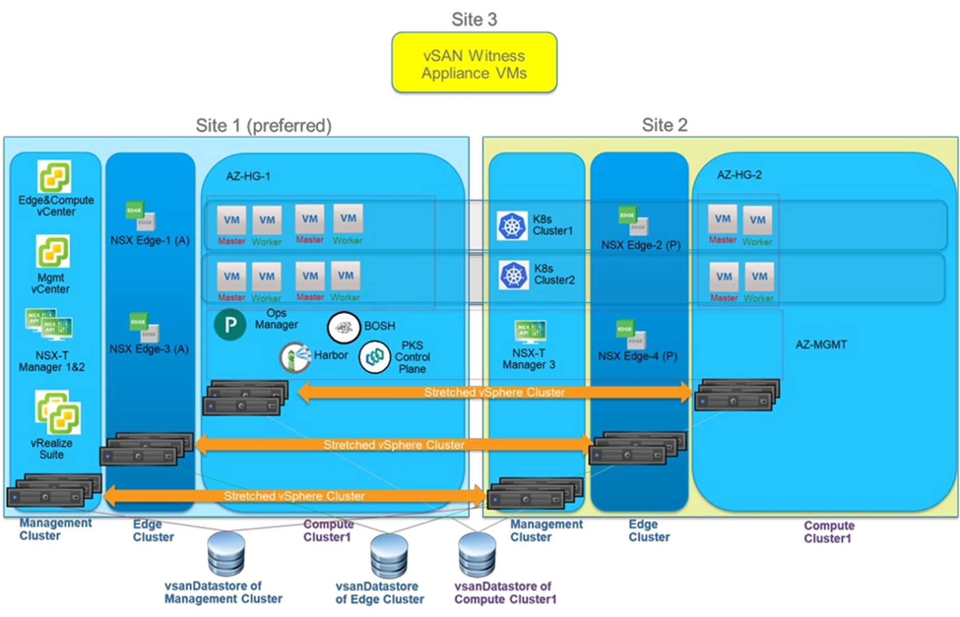
Figure 1. High Level Architecture 1:VMware Enterprise PKS on Three Separate vSAN Stretched Clusters
Architecture 2:
In this topology, the 3 vSphere clusters (Management, Edge and Compute) are collapsed into a single vSphere cluster.
The benefit of this configuration is the total number of ESXi hosts required to run the solution is reduced from 18 to 6. The minimum number of ESXi hosts per datacenter site remains the same (3).
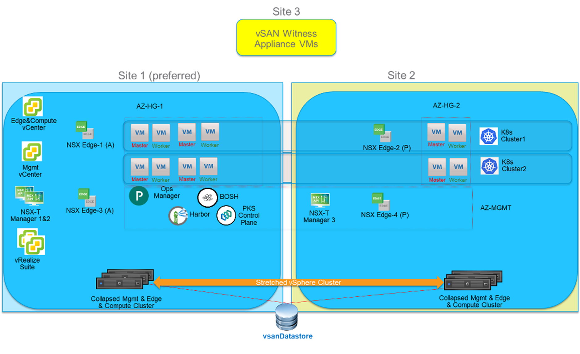
Figure 2. High Level Architecture 2: VMware Enterprise PKS on One Collapsed vSAN Stretched Cluster
Network Configuration
Physical network connection options
There are two options:
1. Each ESXi host with 4 NICs
On each physical server, four Network Interface Card (NIC) ports are used:
- Two NICs are allocated for vSphere Distributed Switch (VDS), used for VMKernel adapters such as management, vMotion and vSAN.
- Two NICs are used for NSX-T n-vds for NSX-T traffic.
2.Each ESXi host with 2 NICs
If the number of physical NICs is a constraint and only two NICs are available in the server, both the NICs are used for NSX-T n-vds. The fully collapsed vSphere cluster NSX-T deployment document can be used to collapse all VMKernel adapters and virtual machine networking traffic to the NSX-T network.
MTU settings
NSX-T requires MTU to be at least 1,600 for the physical switches and NICs. vSAN supports MTU 1,500 and MTU 9,000 and the performance tests show that larger MTU settings can help vSAN improve throughput.
Based on the above requirements, we set the MTU to 9,000 in the whole environment to reduce the physical network management complexity and pursue a higher performance.
Ops Manager Configuration
Bosh resurrector MUST be deactivate to enable Bosh Director work in a vSAN Stretched Cluster environment,
The reason for this configuration is that when a site is down, we will leverage vSphere HA to restart all virtual machines in the other site. If Bosh resurrector is enabled, during a site down event, Bosh may try to resurrect the virtual machines. For resurrecting, Bosh will try to delete the virtual machines first, before recreating it. This will conflict with vSphere HA functioning and produce a race condition, which might lead to unpredictable outcomes.
To deactivate Bosh resurrector, use Ops Manager and go to Bosh tile -> Director Config. Make sure "Enable VM Resurrector Plugin" is unchecked.

Figure 3. Disable Bosh Resurrector in Ops Manager
When configuring the availability zones with Host Groups in Ops Manager, set the ‘VM-Host Affinity Rule’ field to ‘SHOULD’. We will create the corresponding vSphere DRS rule in the next section.

Figure 4. Create ‘SHOULD’ VM-Host Affinity Rule in Ops Manager
vSphere Cluster Configuration
vSphere HA must be enabled in order for the virtual machines to be restarted in case of a site failure.
vSphere DRS must be enabled. Besides, we should create a ‘DRS VM/Host Rule’ with the ‘Should run on hosts in group’ option like depicted in Figure 3. The following virtual machines ‘should’ be placed in Site 1 in a healthy situation:
- Management vCenter
- Edge and Compute vCenter
- NSX-T managers: NSX-T Manager 1 and 2
- vRealize Suite
In case of site 1 failure, these virtual machines are restarted in site 2 by vSphere HA. When site 1 is brought back to healthy state, these virtual machines are vMotioned back to site 1 because they ‘should’ be in site 1 according to the DRS rule.
For the Kubernetes nodes placement, PKS Control Plane also automatically create other corresponding DRS rules that indicate Kubernetes nodes should be in site 1 or site 2. For Kubernetes nodes this is fully automatic and does not require manual DRS rule creation.

Figure 5. Creating a ‘DRS VM/Host Rule’ That Indicates Some Virtual Machines Should Reside in Site 1
Solution Validation
Testing Configuration
Six Kubernetes clusters were deployed. Each Kubernetes cluster was composed of 3 primary nodes and 6 worker nodes.
Each Kubernetes cluster hosted stateless apps and stateful apps:
- Stateless apps: Guestbook and Tea-coffee
- Guestbook leverages Kubernetes service of type LB
- Tea-coffee leverages Kubernetes Ingress
- Stateful apps: Guestbook-pv and Cassandra DB
- Guestbook-pv leverages PV using PVC
- Cassandra DB leverages statefulset with 3 replicas
Expected Behavior
We did the failover and failback testing by totally powering off one whole site: site 1, site 2, or site 3. The expected behaviors are:
When a site is down:
- If some virtual machines are impacted due to a site down, they must be restarted by vSphere HA in the other site.
- Virtual machines must not lose vSAN storage connection because vSAN is still fully functional while it’s in a ‘degraded’ state.
- NSX-T networking is still functioning well.
- Kubernetes clusters can resume to healthy state after the virtual machines are restarted by vSphere HA.
- All stateful and stateless apps can resume to healthy state.
When a site is brought back up:
- The virtual machines that ‘should’ reside in this site defined by DRS rules, are vMotioned back to this site.
- vSAN starts to re-sync data and this is transparent to virtual machines, Kubernetes clusters, stateful and stateless apps.
- NSX-T remains healthy.
- All Kubernetes clusters remain healthy.
- All stateful and stateless apps remain healthy.
Site 1 Failover
We powered off site 1 and monitored the results as below.
Within 5-10 minutes, all expected behaviors were observed. Figure 6 shows the result after the virtual machines were restarted by HA.

Figure 6. Site 1 is Down and the Impacted Virtual Machines are Restarted by HA in Site 2
Site 1 Failback
After the site 1 failover testing was completed, we powered on site 1 and monitored the results as below.
Within 5-10 minutes, all expected behaviors were observed. Figure 7 shows the result after the virtual machines were vMotioned back to site 1.

Figure 7. Site 1 is Powered on and the Impacted Virtual Machines are vMotioned Back to Site 1
Based on the DRS rule, the following virtual machines ‘should’ be in site 1 so they were vMotioned back to site 1:
- Edge and Compute vCenter was vMotioned back to site 1.
- Management vCenter was vMotioned back to site 1.
- NSX-T Manager 1 and 2 were vMotioned back to site 1.
- vRealize Suite was vMotioned back to site 1.
- Ops Manager, Bosh Director, Harbor, VMware Enterprise PKS Control Plane virtual machines were vMotioned back to site 1.
- Some Kubernetes nodes (virtual machines) originally in site 1 were vMotioned back to site 1.
Site 2 Failover
We powered off site 2 and monitored the results as below.
Within 5-10 minutes, all expected behaviors were observed. Figure 8 shows the result after the virtual machines were restarted by HA.

Figure 8. Site 2 is Down and the Impacted Virtual Machines are Restarted by HA in Site 1
NSX-T Manager 3 was restarted in site 1.
All Kubernetes nodes (virtual machines) originally in site 2 were restarted in site 1.
Site 2 Failback
After the site 2 failover testing was completed, we powered on site 2 and monitored the results as below.
Within 5-10 minutes, all expected behaviors were observed. Figure 9 shows the result after the virtual machines were restarted by HA.

Figure 9. Site 2 is Powered on and the Impacted Virtual Machines are vMotioned Back to Site 2
NSX-T Manager 3 was vMotioned back to site 2.
All Kubernetes nodes (virtual machines) originally in site 2 were vMotioned back to site 2.
Production Considerations
The following caveats must be taken into consideration when implementing a VMware Enterprise PKS on vSAN Stretched Cluster solution before going into production.
- When Site 1 and Site 2 are Up and Running:
- Loosing Kubernetes primary nodes quorum will result in loosing access to the Kubernetes cluster. Because BOSH does not try to resurrect any failed Kubernetes node as the resurrector function is disabled.
- If a Kubernetes worker node gets dysfunctional for any reason (file system full, issue with the vNIC, etc.), BOSH will not be able to repair them (BOSH resurrector function is disabled).
- When Site 1 is Down:
- No pks ‘create cluster’ or pks ‘resize cluster’ action is allowed because 1 AZ is down, and Bosh will try to create Kubernetes nodes in this AZ which will ultimately fail.
- Kubernetes nodes that was in DC1 will be restarted in DC2 (thanks to vSphere HA).
- However, Zone Labels on each node won't change (will still refer to original AZ where they were created).
- 'bosh vm' command will display the original AZ where the node was created.
- Note: when DC1 recovers, Kubernetes nodes will move back to their original location (thanks to vSphere DRS) and Zone Labels and 'bosh vm' command display will then be correct.
- When Site 2 is Down:
- No pks ‘create cluster’ or pks ‘resize cluster’ action is allowed because 1 AZ is down, and Bosh will try to create Kubernetes nodes in this AZ which will ultimately fail.
- Kubernetes nodes that were in DC2 will be restarted in DC1 (thanks to vSphere HA).
- However, Zone Labels on each node won't change (will still refer to original AZ where they were created).
- 'bosh vm' command will display the original AZ where the node was created.
- Note: when DC2 recovers, Kubernetes nodes will move back to their original location and Zone Labels and 'bosh vm' command display will then be correct.
Best Practices
When configuring VMware Enterprise PKS in a vSAN cluster, consider the following best practices:
- Enable HA in the vSAN cluster.
- Enable DRS in the vSAN cluster.
- Create a DRS VM/Host Rule with the ‘Must run on hosts in group’ option for NSX-T Edge nodes.
- Create a DRS VM/Host Rule with the ‘Should run on hosts in group’ option for other infrastructure virtual machines.
- In Ops Manager configuration, Bosh resurrector MUST be deactivated to enable Bosh Director work in a vSAN Stretched Cluster environment,
- Use at least 3 primary nodes and 3 worker nodes in Kubernetes clusters to get high availability with Multi-AZ.
- Set MTU equals to 9,000 for all the physical switches.
Conclusion
Overall, deploying, running, and managing VMware Enterprise PKS on VMware vSAN Stretched Cluster provides high availability to the infrastructure services as well as Kubernetes clusters by taking advantages of the security, performance, scalability, operational simplicity, and cost-effectiveness of vSAN. Furthermore, by combining VMware Enterprise PKS, vSAN and NSX-T as a solution, all storage and networking managements including infrastructure and operations of vSphere, vSAN, NSX-T move into a single software stack, thus you do not need two separate infrastructures for traditional storages and containers.
Reference
About the Author
Victor Chen, Solutions Architect in the Product Enablement team of the HCIBU, VMware wrote the original version of this paper. Keith Lee, Francis Guillier, Myles Gray, Shaozhen Ding also contributed to the content and solution validation.