
vSAN Proof of Concept: vSAN Stretched Cluster & Two-Node Overview & Testing
vSAN Stretched Cluster and Two node
Design and Overview
Good working knowledge of how vSAN Stretched Cluster is designed and architected is assumed. Readers unfamiliar with the basics of vSAN Stretched Cluster are urged to review the relevant documentation before proceeding. Details on how to configure a vSAN stretched cluster are found in the vSAN Stretched Cluster Guide. Both ESA and OSA architectures are supported with stretched cluster.
Witness Configuration
The ‘witness’ is usually deployed as an appliance, in a site (fault domain) separate to the two data sites. Although the witness appliance requires access to the vSAN network, only metadata stored on the appliance.
The Witness Appliance can be downloaded from My VMware. The Witness Appliance is deployed as an OVF template, as per the example below:

Note that while two VMkernel adapters are deployed by default on the Witness Appliance, another valid configuration is to tag both vSAN and Management traffic on a single VMkernel adapter for simpler deployments.
After deployment of the OVF, add the Witness Appliance to the vCenter inventory as you would a physical host. Alternatively, customers can use a physical ESXi host for the witness.
The Witness Appliance host must not be added to a cluster, placement should be at the Datacenter level.
Enter the password as per the OVF properties:

Assign the embedded witness appliance license:

Ensure the location is set to the top-level Datacenter:

Once added to vCenter, the Witness Appliance will appear as a host with special properties – again note that the host is deployed at the DC level (note also the OVA “OSA-Witness” deployed below):

Witness Traffic Separation
When a vSAN Witness appliance is deployed, a separately tagged VMkernel interface may be used for witness traffic transit instead of extending the vSAN network to the witness host. This feature allows for a more flexible network configuration by allowing for separate networks for node-to-node vs. node-to-witness communication. Note that this capability can only be enabled from the command line.
Witness Traffic Separation provides the ability to directly connect vSAN data nodes in a 2-node configuration. Traffic destined for the Witness host can be tagged on an alternative physical interface separate from the directly connected network interfaces carrying vSAN traffic. Direct Connect eliminates the need for a dedicated switch at remote offices/branch offices (where the additional cost of the switch could be cost-prohibitive to the solution).

For the example illustrated above, to enable Witness Traffic on vmk1, execute the following on both hosts:
esxcli vsan network ip add -i vmk1 -T=witnessAny VMkernel port not used for vSAN traffic can be used for Witness traffic.
In a more simplistic configuration (as shown below), the Management VMkernel interface (vmk0) could be tagged for Witness traffic. The VMkernel port tagged for Witness traffic needs to have IP connectivity to the vSAN traffic tagged interface on the vSAN Witness Appliance.

The minimum requirement for this setup is a single vnic uplink and vmkernel port carrying both management and vSAN traffic.
Shared Witness
A ‘shared’ witness can be used for several vSAN two-node setups (i.e. across multiple two-node clusters), reducing the number of separate witness appliances needed. Note that shared witness is not supported for stretched cluster.

For more information on vSAN Witness VM sizes refer to the official documentation: https://docs.vmware.com/en/VMware-vSphere/8.0/vsan-planning/GUID-05C1737A-5FBA-4AEE-BDB8-3BF5DE569E0A.html
Stretched Cluster Setup
To start the configuration wizard for either vSAN stretched cluster or two-node, navigate to [Cluster] > Configure > vSAN > Services and pick the appropriate option:

Follow the screens to configure the disks, as per a standard vSAN cluster. Then chose the vSAN witness host:

For an OSA cluster, select the disks for the witness host:

Stretched Cluster Setup: Manual Configuration
Instead of using the configuration wizard above, to manually configure the stretched cluster (after vSAN has been enabled) navigate to [vSAN cluster] > Configure > vSAN > Fault Domains and click on ‘Configure Stretched Cluster’:

Configure the hosts into the appropriate domain:

Select the Witness host:

For an OSA witness, the first time you configure vSAN with a witness host you will claim the disks used by the witness, when adding additional clusters this step is skipped.

This is covered in greater detail in the vSAN Stretched Cluster Guide.
Stretched Cluster Hosts
Our example has four ESXi hosts in a cluster, two ESXi hosts on data site A (the “preferred” site), and two hosts on data site B (the “secondary” site). There is one disk group per host. The witness host/appliance is deployed in a 3rd remote data center. This configuration is referred to as 2+2+1.
VMs are deployed on both the “Preferred” and “Secondary” sites of the vSAN Stretched Cluster. VMs are running/active on both sites.
Stretched Cluster Network Topology
As per the vSAN Stretched Cluster Guide, several different network topologies are supported for vSAN Stretched Cluster. Considerations include layer 2 (same subnet) or layer 3 (routed) connectivity between the three sites with or without Witness Traffic Separation (WTS) depending on the requirements.
Some of the common designs listed below. Options 1 and 2 are configurations without WTS. The only difference between them is whether the network is stretched (Layer 2) or routed (Layer 3) for vSAN data traffic. Option 3 uses Witness Traffic Separation. For simplicity, all options use L2 for VM traffic. During testing, you may choose to test one or another, or both options if you wish.
For more information on network design best practices for the stretched cluster, refer to the vSAN Stretched Cluster Guide.
Example Stretched Cluster Network Configurations
As per the vSAN Stretched Cluster Guide, several different network topologies are supported for vSAN Stretched Cluster. The options below provide some of the different for stretched cluster network configuration.
Option 1:
- L3 for witness traffic, without Witness Traffic Separation
- L2 for vSAN data traffic between data sites
- L2 for VM traffic

Option 2:
- L3 for witness traffic, without Witness Traffic Separation
- L3 for vSAN data traffic between data sites
- L2 for VM traffic

Option 3:
- L3 for witness traffic with Witness Traffic Separation
- L2 for vSAN data traffic between data sites
- L2 for VM traffic

vSAN Stretched Cluster Lab Setup
As per the vSAN Stretched Cluster Guide, several different network topologies are supported for vSAN Stretched Cluster.
The network topology deployed in this lab environment for our test case is layer 2 between the vSAN data sites and L3 between data sites and witness. ESXi hosts and vCenter are in the same L2 subnet for this setup. The VM network should be a stretched L2 between both data sites as the unique IP used by the VM can remain unchanged in a failure scenario.
There are four ESXi hosts in this cluster, two ESXi hosts on data site A (the “preferred” site) and two hosts on data site B (the “secondary” site). There is one disk group per host. The witness host/appliance is deployed in a 3rd, remote data center. The configuration is referred to as 2+2+1.
VMs are deployed on both the “Preferred” and “Secondary” sites of the vSAN Stretched Cluster. VMs are running/active on both sites.
Below is a diagram detailing the environment used for the Stretched Cluster testing.
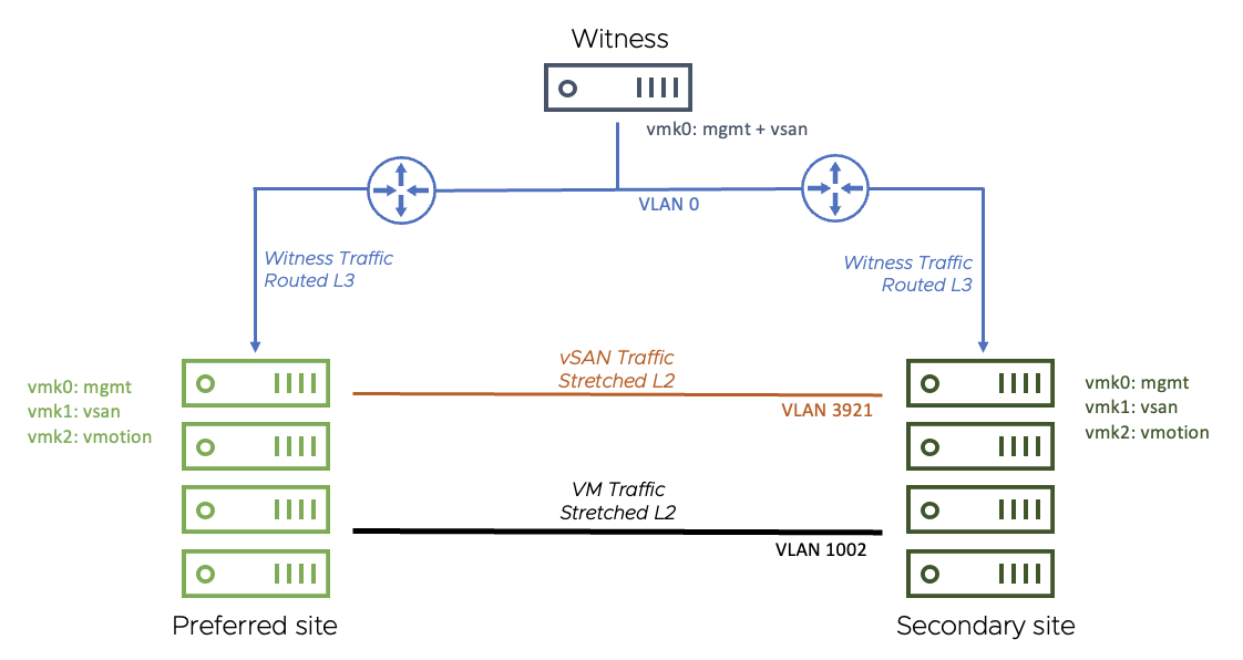
- This configuration uses a stretched (layer 2) network for vSAN traffic between sites
- A routed network is used between data each data site and the witness site
- For both data sites, the vSAN network is on VLAN 3921. The gateway is 172.21.0.1
- The Witness Appliance: vmk0 has been tagged for management and vSAN and is on the native vLAN (vLAN 0). The gateway is 10.156.159.253
The VM network is stretched (layer 2) between the data sites on VLAN 106 (since no VMs run on the Witness Appliance, there is no need to extend this network to the third site)
Preferred / Secondary Site Details
In vSAN Stretched Clusters, the ‘preferred’ site simply means the site that the witness will ‘bind’ to in the event of an inter-site link failure between the data sites. This will also be the site where all VMs will run when there is an inter-site link failure.
For our failure scenarios, we create two DVS port groups and add the appropriate vmkernel port to each, ready to test the failover behavior:

On each of the hosts, vSAN traffic is tagged on vmk1, with the default gateway set on the vSAN network

The routing table shows the gateways set:

The witness appliance has one vmkernel adapter, with both management and vSAN tagged. The default gateway is on the management network.

Note: The Witness Appliance is a nested ESXi host and requires the same treatment as a standard ESXi host (i.e, for lifecycle management). Keep all ESXi hosts in a vSAN cluster at the same update level, including the Witness appliance.
vSphere HA Settings
vSphere HA plays a critical part in Stretched Cluster. HA is required to restart virtual machines on other hosts and even the other site depending on the different failures that may occur in the cluster. The following section covers the recommended settings for vSphere HA in a Stretched Cluster environment.
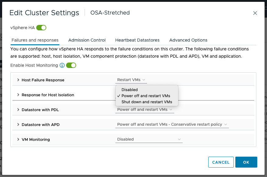
Response to Host Isolation
The recommendation is to “Power off and restart VMs” on isolation, as shown below. In cases where the virtual machine can no longer access the majority of its object components, it may not be possible to shut down the guest OS running in the virtual machine. Therefore, the “Power off and restart VMs” option is recommended.
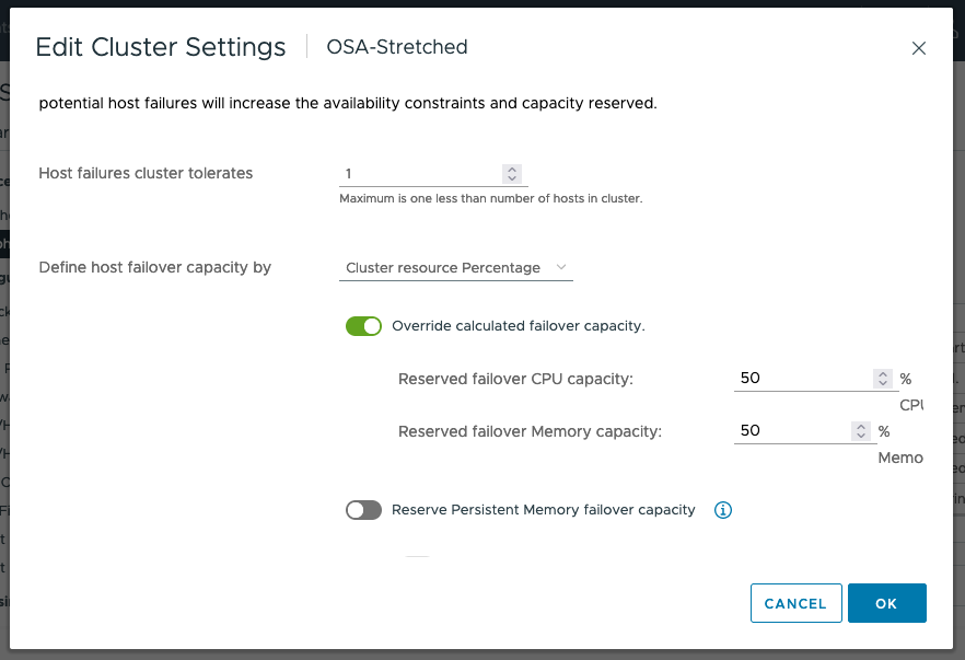
Admission Control
If a full site fails, the desire is to have all virtual machines run on the remaining site. To allow a single data site to run all virtual machines if the other data site fails, the recommendation is to set Admission Control to 50% for CPU and Memory as shown below.
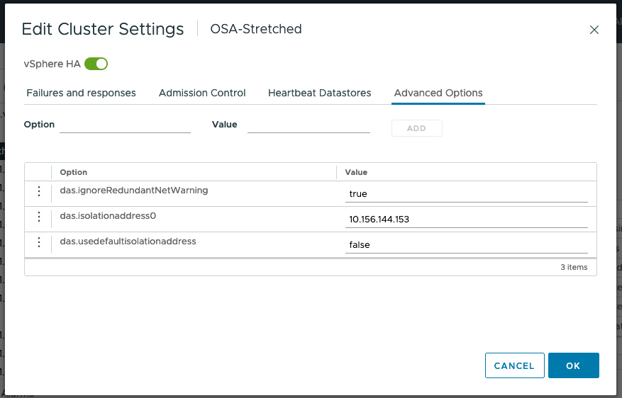
Advanced Settings
The default isolation address uses the default gateway of the management network. This will not be useful in a vSAN Stretched Cluster when the vSAN network is broken. Therefore, the default isolation response address should be turned off. This is done via the advanced setting das.usedefaultisolationaddress to false.
To deal with failures occurring on the vSAN network, VMware recommends setting at least one isolation address which is reachable from each of the data sites. In this example, we use the gateway IP address of the witness host network. Use the advanced setting das.isolationaddress0 to set the isolation address for the IP gateway address to reach the witness host.
Finally, we set das.ignoreRedundantNetWarning to silence the warnings for redundant networks.
Note: Since vSAN 6.5 there is no need for VM anti-affinity rules or VM to host affinity rules in HA
Host/VM Groups and Site Affinity
The next step is to configure the Host/VM groups and define which VMs should run on each site. VMs will be restarted on the remote site only if there is a catastrophic failure (or a significant resource shortage).
First, we create host groups, by navigating to [Cluster] > Configure > Configuration > VM/Host Groups.

Create groups for the primary and secondary site for both the hosts and VMs. In the example below, the Host Groups are named Preferred and Secondary:

Next, we define the affinity rules that specify where the VMs should run. Navigate to [Cluster] > Configure > Configuration > VM/Host Rules

Here we add a should “VM to Host” rule that binds the primary site VMs to the preferred site:

Note that “should” rules (as opposed to “must” rules) mean that every attempt will be made to adhere to the affinity rules. However, if this is not possible (due lack of resources), the other site will be used for hosting the virtual machine.
Also, note that the vSphere HA rule setting is set to “should”. This means that if there is a catastrophic failure on the site to which the VM has an affinity, HA will restart the virtual machine on the other site. If this was a “must” rule, HA would not start the VM on the other site.
The same settings are necessary on both the primary VM/Host group and the secondary VM/Host group.
DRS Settings
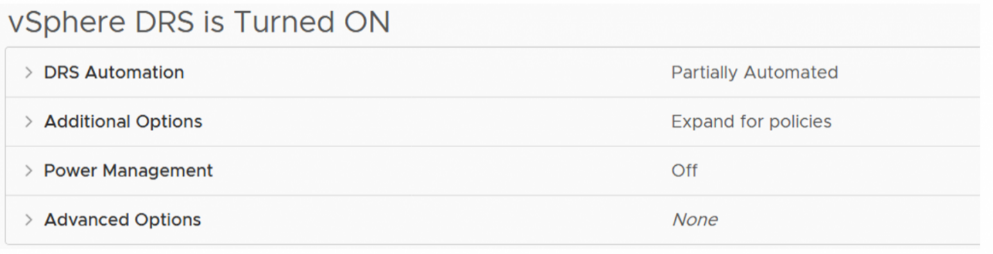
In this example, DRS is set to ‘partially automated’, which is the recommended setting for a stretched cluster. This is to avoid failback of VMs occurring while rebuild activity is still taking place. More on this later.
vSAN Stretched Cluster Local Failure Protection
We build on resiliency by including local failure protection, which provides storage redundancy within each site and across sites. Local failure protection is achieved by implementing local RAID-1 mirroring or RAID-5/6 erasure coding within each site. This means that we can protect the objects against failures within a site. For example, if there is a host failure on site 1, vSAN can self-heal within site 1 without having to go to site 2 if properly configured.

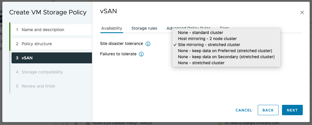
Local Failure Protection is configured and managed through storage policies. The figure below shows rules in a storage policy that is part of an all-flash stretched cluster configuration. The "Site disaster tolerance" is set to Dual site mirroring (stretched cluster), which instructs vSAN to mirror data across the two main sites of the stretched cluster. The "Failures to tolerate" specifies how data is protected within the site. In the example storage policy below, 1 failure - RAID-5 (Erasure Coding) is used, which can tolerate the loss of a host within the site.

Local failure protection within a stretched cluster further improves the resiliency of the cluster to minimize unplanned downtime. This feature also reduces or eliminates cross-site traffic in cases where components need to be resynchronized or rebuilt. vSAN lowers the total cost of ownership of a stretched cluster solution as there is no need to purchase additional hardware or software to achieve this level of resiliency.
vSAN Stretched Cluster Site Affinity
Storage policy-based management for stretched clusters includes the “Affinity” rule. You can specify a single site to locate VM objects in cases where cross-site redundancy is not needed. Common examples include applications that have built-in replication or redundancy such as Microsoft Active Directory and Oracle Real Application Clusters (RAC). This capability reduces costs by minimizing the storage and network resources used by these workloads.
Site affinity is easy to configure and manage using storage policy-based management. A storage policy is created, and the Affinity rule is added to specify the site where a VM’s objects will be stored:
vSAN Stretched Cluster Preferred Site Override
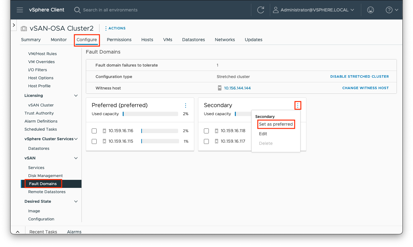
Preferred and secondary sites are defined during cluster creation. If it is desired to switch the roles between the two data sites, you can navigate to [vSAN cluster] > Configure > vSAN > Fault Domains, select the ellipses to the right of the ‘Secondary’ site pane and click the ‘Set as preffered’ option.
vSAN Stretched Cluster and Two Node Failure Scenarios
In this section, we will look at how to inject various network failures in a vSAN Stretched Cluster configuration. We will see how the failure manifests itself in the cluster, focusing on the vSAN health check and the alarms/events as reported in the vSphere client.
Note that network failover scenarios for stretched Cluster (with or without witness traffic separation) and 2-node (with or without direct connect) are the same because the Witness traffic is always connected via routed (L3) network.
Scenario #1: Network Failure between Data Site and Witness

Trigger the Event
To make the either the primary or secondary site lose access to the witness site, one can simply remove the gateway configured on the vSAN VMkernel adapter.
First choose which site to operate on (either the primary or secondary hosts). Open an SSH session to each host on the chosen site. Our first step is to confirm which VMkernel adapter is being used for vSAN:
[root@localhost:~] esxcli vsan network list | grep VmkNic
   VmkNic Name: vmk1
Then get the details for this adapter, and make a note of the output:
[root@localhost:~] esxcli network ip interface ipv4 get -i vmk1
Name  IPv4 Address  IPv4 Netmask   IPv4 Broadcast  Address Type  Gateway     DHCP DNS
----  ------------  -------------  --------------  ------------  ----------  --------
vmk1  172.21.4.12   255.255.240.0  172.21.15.255   STATIC        172.21.0.1     false
We can then effectively remove the gateway set for this adapter by re-applying the same IP address and omitting the gateway address. For example:
esxcli network ip interface ipv4 set -i vmk1 -t static -I 172.21.4.12 -N 255.255.240.0
Optionally, we can achieve this using a quick script (remember to change the values of the VMkernel adaptor and netmask):
ip=$(esxcli network ip interface ipv4 get -i vmk1 | grep vmk1 | awk '{print $2}')
esxcli network ip interface ipv4 set -i vmk1 -t static -I $ip -N 255.255.240.0
For a more detailed script, see:
https://github.com/vmware-tanzu-experiments/vsphere-with-tanzu-proof-of-concept-samples/blob/main/VCF/vSAN-net-gw-operations.md
Cluster Behavior on Failure
In such a failure scenario (where the witness is isolated from one of the data sites) the implication is that there is no communication to both the master node AND the backup node. In stretched clusters, the master node and the backup node are placed on different fault domains (i.e. sites).
This is the case in this failure scenario. The witness becomes isolated, and the nodes on the preferred and secondary sites remain in the cluster. We can see how this is shown in vCenter below.
To begin with, the Cluster Summary view shows us a few errors:

Clicking on the ‘view all issues’ link shows the full extent of the issues:

On navigating to the [vSAN Cluster] > Monitor > vSAN > Health view, there are a lot of checks showing errors, including failed pings to the witness appliance:

One final place to examine is virtual machines. Navigate to [vSAN cluster] > Monitor > vSAN > Virtual Objects > View Placement Details. It should show the witness absent from the secondary site perspective. However, virtual machines should still be running and fully accessible.

Returning to the health check, selecting Data > vSAN object health, you can see the error 'Reduced availability with no rebuild - delay timer'

Conclusion
The loss of the witness does not impact the running virtual machines on the secondary site. There is still a quorum of components available per object, available from the data sites. Since there is only a single witness host/site, and only three fault domains, there is no rebuilding/resyncing of objects.
Repair the Failure
Add the gateway IP address back to the VMkernel adapter on the affected hosts, for example:
esxcli network ip interface ipv4 set -i vmk1 -t static -g 172.21.0.1 -I 172.21.4.12 -N 255.255.240.0
Scenario #2: Network Failure from both Data sites to Witness

Trigger the Event
Similar to the last test, we can remove the gateway configured on the vSAN VMkernel adapter.
Here we open an SSH session to every host (on both sites). Again, confirm which VMkernel adapter is being used for vSAN:
[root@localhost:~] esxcli vsan network list | grep VmkNic
   VmkNic Name: vmk1
Then get the details for this adapter, and make a note of the output:
[root@localhost:~] esxcli network ip interface ipv4 get -i vmk1
Name  IPv4 Address  IPv4 Netmask   IPv4 Broadcast  Address Type  Gateway     DHCP DNS
----  ------------  -------------  --------------  ------------  ----------  --------
vmk1  172.21.4.12   255.255.240.0  172.21.15.255   STATIC        172.21.0.1     false
We can then effectively remove the gateway set for this adapter by re-applying the same IP address and omitting the gateway address. For example:
esxcli network ip interface ipv4 set -i vmk1 -t static -I 172.21.4.12 -N 255.255.240.0
Optionally, we can achieve this using a quick script (remember to change the values of the VMkernel adaptor and netmask):
ip=$(esxcli network ip interface ipv4 get -i vmk1 | grep vmk1 | awk '{print $2}')
esxcli network ip interface ipv4 set -i vmk1 -t static -I $ip -N 255.255.240.0
For a more detailed script, see:
https://github.com/vmware-tanzu-experiments/vsphere-with-tanzu-proof-of-concept-samples/blob/main/VCF/vSAN-net-gw-operations.md
Cluster Behavior on Failure
The events observed are for the most part identical to those observed in the previous test.

And again, we have a vSAN network partition, with the data sites and witness appliance separated:

Conclusion
When the vSAN network fails between the witness site and both the data sites (as in the witness site fully losing its WAN access), it does not impact the running virtual machines. There is still a quorum of components available per object, available from the data sites. However, as explained previously, since there is only a single witness host/site, and only three fault domains, there is no rebuilding/resyncing of objects.
Repair the Failure
Just as before, add the gateway IP address back to the VMkernel adapter on all the hosts. For example:
esxcli network ip interface ipv4 set -i vmk1 -t static -g 172.21.0.1 -I 172.21.4.12 -N 255.255.240.0
Scenario #3: Secondary Site Failure

Trigger the Event
Power off the hosts in the secondary site (either physically or via the host management console).
Cluster Behavior on Failure
In the first instance, hosts will show communication failures, such as:

![]()
We can see the hosts are shown as ‘not responding’ and the ‘unexpected number of fault domains’ indicates that we have lost a site.

Clicking on ‘view all issues’ shows more information and indicates that we have a HA event:

Thus, all VMs from the secondary data site will be restarted via HA on the Preferred data site. As we only have one data site (fault domain) left, the storage policy will be non-compliant. If we look at the VMs on the cluster, we can see that this is the case. Below we have added the columns for ‘host’, ‘uptime’ and ‘VM storage policy compliance’ to illustrate this:

Verify on each host or via [vSAN cluster] -> VMs if all VMs were restarted on the preferred site.
Conclusion
When the secondary site fails, it does not impact the running VMs on the primary data site as quorum exists. VMs on the failed site will be restarted via HA on the available data site. Again, since there are only three fault domains, there is no rebuilding or resyncing of objects (and thus the storage policies are shown as non-compliant).
Repair the Failure
Power on the hosts on the secondary site. If DRS was set to ‘fully automated’ then VMs will be moved back to the secondary site. Otherwise, they will need to be moved back to the correct site.
Scenario #4: Primary Site Failure

Trigger the Event
Power off the hosts in the secondary site (either physically or via the host management console).
Cluster Behavior on Failure
As before, the first error is reported back from the remaining powered on hosts (i.e. on the secondary site)
Looking at the cluster issues, we see the host power state and subsequent HA event:

And, as per the previous test, the VMs on the affected site are restarted to run on the active site:

The storage policy is shown as non-compliant as we do not have enough fault domains to fulfil the policy requirements. Looking at the objects in the cluster, we can see the status as ‘reduced availability with no rebuild’ – as there is no other fault domain to rebuild to.

Conclusion
As per the previous test, after losing a data site, HA restarts the VMs on the remaining, active site. Again, there is no rebuild of components as only one data site is available.
Repair the Failure
Power on the hosts on the primary site. If DRS was set to ‘fully automated’ then VMs will be moved back to the secondary site. Otherwise, they will need to be moved back to the correct site.
Scenario #5: Network Failure between Data Sites but Witness Still Accessible

Trigger the Event
Link failure between preferred and secondary data sites simulates a datacenter link failure while witness traffic remains up and running.
For this test, we can either physically disable the network link between the data sites or use the DVS traffic filter function.
To use the DVS traffic filter, navigate to the port group used for the preferred site, then Configure > Traffic filtering and marking, as shown below:

Here, we create filter rule for each host on the preferred site to all hosts on the secondary site, selecting the action as ‘drop’ with ‘any’ protocol between the IP addresses (thus, for four hosts, we need 16 rules in total):

We can then enable the newly created DVS filters:

Cluster Behavior on Failure
As expected, we observe network errors and a cluster partition:

The VMs are restarted by HA on the preferred site:

Conclusion
In the failure scenario, if the data link between data centers is disrupted, HA will start the VMs on the preferred site. There is still a quorum of components available per object, available from the data sites. As previously discussed, there is only one data site remaining, therefore there is no rebuilding/resyncing of objects.
Repair the Failure
Disable the DVS filter rules and rerun the health check tests. Verify that all tests pass successfully and that there are no remaining errors on the cluster, hosts or VMs.