
Configuring NVMeoF TCP
Configuring NVMe-TCP
Configuring NVMe-TCP in vSphere is simple and doesn’t require special hardware. NVMe-TCP uses standard Ethernet HW and can be converged with other traffic. Now, a best practice would be to dedicate NICs for NVMe-TCP for maximum performance but is not required. It should be noted NVMe-TCP or NVMe, in general, can utilize much, if not all, of the available bandwidth. Subsequently, converging NVMe-TCP with other traffic without enough bandwidth could impact other network traffic.
This article will detail the process of setting up NVMe-TCP in vSphere.
Network Requirements
Before you configure the storage piece, you first must configure the network. It is recommended you use port binding for NVMe-TCP. You will need to create a vmk for each subnet you are using. A vmhba/NIC pair can have multiple vmks associated with it.

Configuring NVMe over TCP on ESXi
If your array target controllers are on the same VLAN/subnet, you can use a single switch with multiple Portgroups. If your array target controllers are on separate VLANs/subnets, you can use a separate switch and separate portgroups for each VLAN/subnet or a single switch with multiple portgroups. Both configurations are supported with NVMe-TCP. The setup for NVMe-TCP is similar to iSCSI with the difference being the virtual NVMe adaptors. You will create a virtual NVMe adaptor for each NIC to be used for NVMe-TCP.
In this example, the array controllers are on the same VLAN/subnet as the vmhba/NIC pairs. As a result, I only needed to create a Portgroup for each uplink, within the existing vSwitch for NVMe-TCP. I am converging on a 10Gb link for the example, but again I want to remind you to make sure you have adequate bandwidth when converging network traffic.
If needed, you can use NIOC to manage bandwidth for specific traffic. NIOC is only available with certain vSphere levels.
Virtual Switch Examples
There are a few combinations of vSwitch/DVSwitch that are supported.
- Multiple Subnets, Multiples Switches, Multiple Portgroups.
- Multiple Subnets, Single vSwitch, Multiple Portgroups.
- Single Subnet, Single vSwitch, Multiple Portgroups
When configuring your NVMe-TCP connectivity, there will be a NIC-to-vmhba pair for every NIC used for NVMe-TCP.
Below are some examples of the supported configurations. Note the physical networking portion can vary depending on the customer's implementation. The physical aspect in these examples is one possible configuration.
 |
 |
 |
More Advanced configurations
In cases where your array controllers are in different subnets/VLANs. There is a more advanced configuration needed ensure each NIC used has a path to each controller. In these configs, you will see there are two VMKs per NIC, one for each subnet/VLAN. When using these configurations, if you are NOT using VLANs to separate traffic, you should set a per VMK gateway to ensure proper routing.
Failover policy must be set for all 4 portgroups such that pg1 and pg3 bind to vmnic1 and pg2 and pg4 bind to vmnic2
 |
 |
Network Portgroup Configuration
Reviewing the Portgroup setup, you will see each NIC is explicitly active with no failover. For each vmk used, a Portgroup should be set up such that only one NIC is active and all other NICs are set to unused.

VMkernel Configuration
Once the Portgroups have been created, you can then set up your vmks for each NIC used. Under VMkernel adapters on your host, add new VMkernel.

Select one of the Portgroups you created for NVMe-TCP. Remember you will do this for each NIC/vmhba pair used.

Under the Port properties, you will select the NVMe over TCP under "Enable Services". On this screen, you can also change the default MTU depending on what your network uses.

On the next screen, you will enter your IP information for the vmk. Another best practice is not to route your traffic if possible, each hop can add latency.

Once you finish entering the data and click finish, you will have created a vmk for NVMe-TCP. Make sure to repeat this process for all NIC/vmhba pairs to be used for NVMe-TCP.

Configuring NVMe-TCP Adapters
After completing the vmk setup, you can now add the NVME over TCP adapters for each NIC to be used for NVMe-TCP. In the host configuration, under Storage Adapters, you ADD SOFTWARE ADAPTER selecting NVMe over TCP.

On the Add Software NVMe over TCP adapter screen, you will select the NICs you configured for NVMe-TCP. Again, you will add an SW NVMe-TCP adapter for each NIC you configured previously.
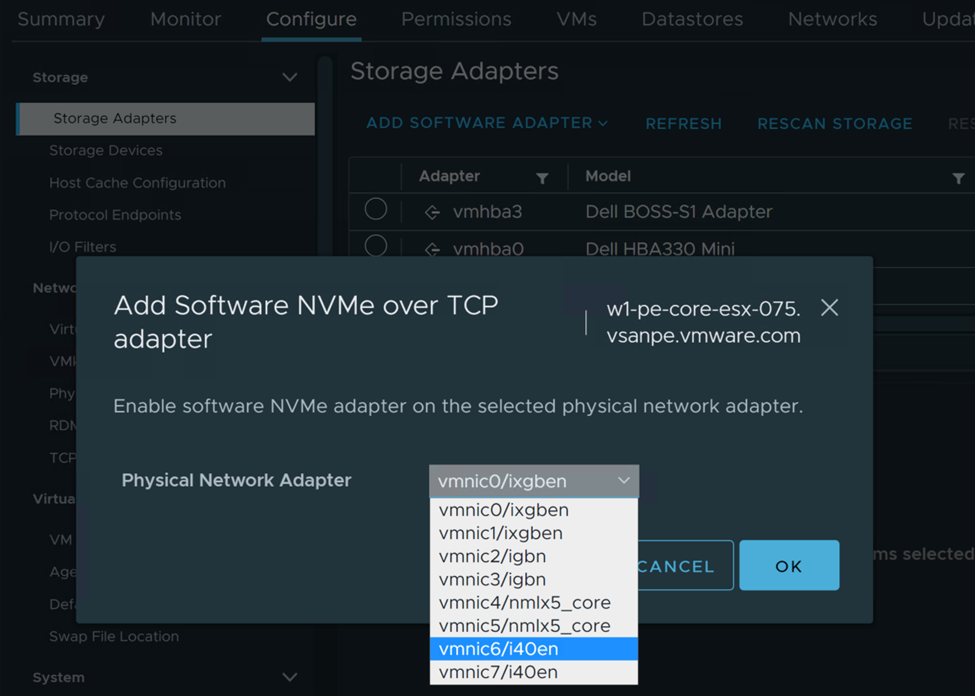
In this example, we configured two NICs to be used for NVMe-TCP so we will have two SW NVMe over TCP adapters.

Adding Storage Controller
Now that the network, NICs, vmks, and SW NVMe-TCP adapters have been created, we will add the storage controllers.
In this example, we are using an Infinidat Infinibox, so some of these steps may vary based on the array vendor you are using. Make sure to review your array vendor’s documentation to ensure you set up the NVMe targets correctly.
Under the Storage Adapters configuration, select one of the SW NVMe-TCP adapters, then select Controllers. Under Controllers, you select ADD CONTROLLER.

On the ADD CONTROLLER screen, you will see the Host NQN, this is similar to the iSCSI IQN, but for NVMe. Click COPY, you will need to add each SW NVMe-TCP host’s NQN to the storage array. NOTE: the NQN is unique to the host, not the adapters. So you will only need to copy the NQN to the array from one of the SW NVME-TCP adapters for each host.

Example of Storage Array Configuration
On the array side, you will create host groups/clusters similar to the way you would for iSCSI.
DO NOT use any of the iSCSI host groups for the NVMe targets or add an NVMe NQN to a SCSI target. NVMe is a completely different protocol/transport and and mixing transports could result in data corruption.
Here you can see I’ve created a host profile for each host in the vSphere cluster.

For each host in the vSphere cluster that will be accessing the NVMe target, add that respective host’s NQN to the corresponding profile on the array.
Select ADD PORT

Choose NVMe-OF

Depending on the array, it may already see the host’s NQN, select the correct NQN for the host profile.

Adding Controller Details
Back to the vSphere host, in the Add Controller setup, you will add the IP for the NVMe-TCP interface and then click on DISCOVER CONTROLLERS. If everything has been properly configured, it will populate all the controller interfaces in the adapter. Then click on OK to finish. You will repeat the adding controller portion for each SW NVMe-TCP adapter configured on each host. In this example, we have two SW NVMe-TCP adapters, and three hosts. So, I repeated the process 5 more times.

Once completed, you will see the controllers listed under Controller for each SW NVMe-TCP adapter.

You should verify the array is also connected to all the adapters as well.

Mapping Volume
Now that the connectivity has been configured, you can create the map to a new NVMe volume for the hosts.
Again, this example is for an Infinibox and will vary from vendor to vendor.


Once the volume has been mapped to the hosts, it will show up in the SW NVMe-TCP adapter’s Devices. No storage rescan is required for NVMe.

You can also see the Namespace details for the volumes.

You can go into Storage Devices and you will see the NVMe-TCP disk and the details.

Creating New Datastore
At this point, all configurations should be completed and you can now create a new VMFS Datastore. On one of the hosts, right-click and select Storage, New Datastore.

Then you will select the Namespace volume you created in the previous steps.

Select VMFS6.

In the next screen, you can Use all available partitions or a subset of the space. Typically you would use all available partitions/space.

Review the details for your new Datastore and click Finish.

Your new Datastore will be created and should be attached to all hosts configured with access. Notice the Drive type is Flash.

Summary
- Ensure you have adequate network bandwidth when converging NVMe-TCP with other vSphere traffic. If possible, dedicate NICs for NVMe-TCP to attain best possible performance.
- Make sure to complete the required host steps on all vSphere hosts connecting to the NVMeoF target volume (Namespace).
- Make sure you DO NOT add any of the host’s NQN to an existing iSCSI volume! Create new NVMe specific host profiles for the NVMe target volume(s).
- You can connect to the same array via SCSI and NVMe at the same time. You just cannot connect to the same targets. For example, you could have an iSCSI LUN Datastore and an NVMe-TCP Namespace Datastore from the same array connecting to the same set of hosts.
NVMeoF Resources
I've created and NVMeoF Resource page to help with many of the NVMeoF docs, KB articles and other resources.