
Enterprise PKS on VCF Pre-requisites
Enterprise PKS on VMware Cloud Foundation Deployment Overview
This document provides an overview of the steps needed to deploy Enterprise PKS on an NSX-T backed domain in VMware Cloud Foundation.
Summary of Cloud Foundation Requirements
The table below provides a summary of the tasks to be completed prior to deploying Enterprise PKS on Cloud Foundation. Details on how to perform these tasks are explained in the sections that follow.
Cloud Foundation Requirements
|
Task |
Notes |
|
VCF Bring-up |
Deploy Cloud Foundation. Ensure the Management Domain is fully operational with no alerts or alarms. Run “/opt/vmware/sddcsupport/sos –health-check” and verify all checks pass prior to deploying Enterprise PKS.
|
|
Three available hosts |
Three hosts are required for creating a VI domain; however it is recommended you use at least four hosts for redundancy and to facilitate server maintenance. Verify a minimum of three ESXi hosts are available for the PKS Domain.
|
|
Download PKS and NSX-T bundles |
You must download the NSX-T and PKS installation bundles that are applicable to the version of Cloud Foundation you are running.
|
|
NSX-T License |
You must add an NSX-T license to the SDDC Manager license repository. This license is used to license NSX-T inside the VI domain backing the PKS solution.
|
|
Create NSX-T Backed VI Domain |
Create a VI domain with NSX-T. Enterprise PSK requires NSX-T.
|
|
Deploy the NSX Edge Cluster |
After creating the VI domain, login to NSX-T and create an NSX-T “Edge Cluster” with an associated T0 and T1 router. |
Summary of Enterprise PKS Requirements
Enterprise PKS requires two NSX-T overlay networks. One for the PKS Management Plane and one for the PKS Control plane. These networks are defined as segments (logical switches) off the Tier 1 router. The IP subnets must be routable.
|
Network |
Type |
Subnet |
Notes |
|
PKS Management |
Overlay |
192.168.51.0/24 |
|
|
PKS Service |
Overlay |
192.168.51.0/24 |
|
Along with the two overlay networks, two IP Blocks and one IP Pools need to be created to preallocate IP addresses to be used by Enterprise PKS when deploying K8s clusters.
|
Network |
Subnet |
Notes |
|
Load Balancer |
172.17.36.0/24 |
Routable IP network that will be used for the external load balancers |
|
Node Block |
30.0.0.0/16 |
IP addresses range used for the K8s nodes. Note the ‘/16’ CIDR |
|
Pod Block |
40.0.0.0/16 |
IP addresses range used for the K8s nodes. Note the ‘/16’ CIDR |
Enterprise PKS on VMware Cloud Foundation Deployment Notes:
Cloud Foundation supports the Enterprise PKS “No-NAT with Logical Switch Topology”.
Refer to the Installing Pivotol PKS 1.5 Installation guide (https://docs.pivotal.io/pks/14/nsxt-topologies.html) for a description of the supported Pivotal PKS deployment topologies. Note that Cloud Foundation 3.9.x provides support for the “No-NAT with Logical Switch Topology”. With this topology, the IPs for the PKS Management plane, PKS Control Plane and K8s node networks must be routable.
When configuring NSX-T, use the “Advanced Network & Security” tab. From the PKS 1.4 Release Notes (https://docs.pivotal.io/pks/1-4/release-notes.html):
NSX-T v2.4 introduced a new Policy API and a new NSX Manager user interface (UI) based on the Policy API. However, Enterprise PKS does not support the Policy API or Policy-based UI. Enterprise PKS supports the NSX Management API, which is exposed via the “Advanced Networking” tab of the of the NSX Manager UI. When installing and configuring NSX-T for use with Enterprise PKS, use the “Advanced Networking and Security” tab to create any required networking objects.
Cloud Foundation Deployment
Prior to deploying Enterprise PKS, Cloud Foundation needs to be deployed with a healthy Management Domain.
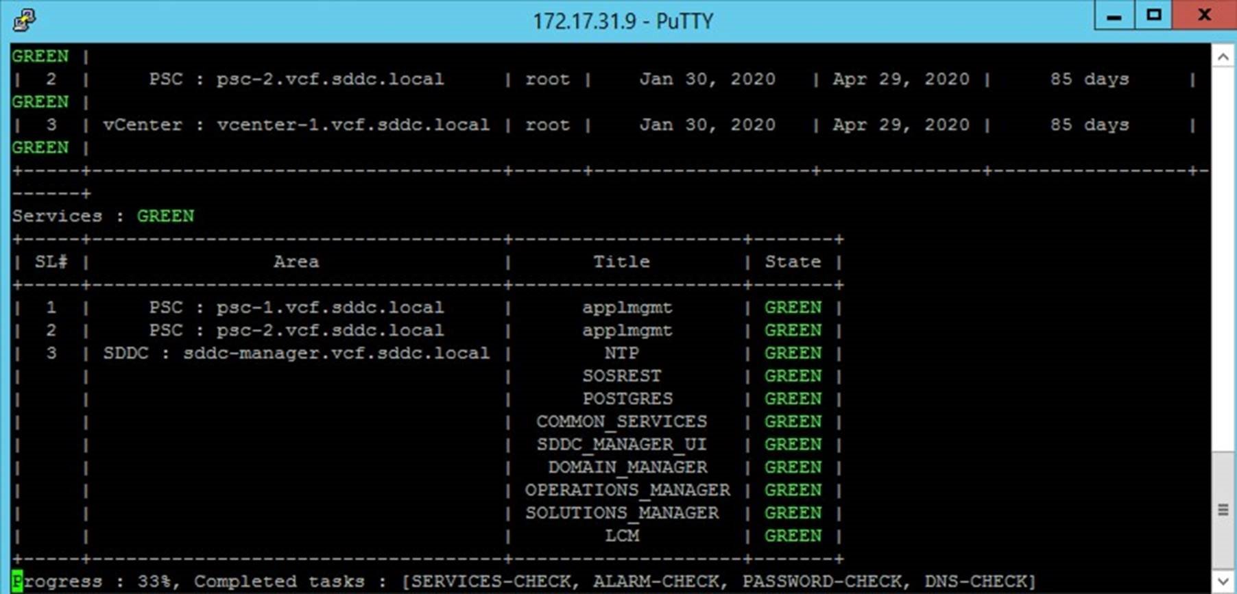
SSH to the SDDC Manager and run the “/opt/vmware/sddc-support/sos –health-check” command. Verify that all checks pass successfully. Resolve any issues before proceeding with the deployment of Enterprise PKS.
Prerequisites:
• SSH access to the SDDC Manager
• Login Credentials to the SDDC Manager
Procedure:
• SSH to the SDDC Manager
• cd /opt/vmware/sddc-support
• Execute the command: ./sos --health-check
• Verify the state for all checks is “Green”
Add Hosts to Cloud Foundation Inventory
A minimum of three hosts must be available (unassigned) in the host free pool for use in a VI Domain that will provide the infrastructure for the Enterprise PKS solution.
Note: A minimum of three hosts are required, however, four hosts are recommended to provide redundancy and to facilitate host maintenance.
Prerequisites:
• ESXi must installed on the hosts to be added. Verify the ESXi version with the VCF BOM.
• (optional) If adding multiple hosts, a JSON file can be used for adding hosts in bulk
Values used in this example:
|
Host |
IP Address |
FQHN |
|
|
esxi-5 |
172.17.31.105 |
esxi-5.vcf.sddc.local |
|
|
esxi-6 |
172.17.31.106 |
esxi-6.vcf.sddc.local |
|
|
esxi-7 |
172.17.31.107 |
esxi-7.vcf.sddc.local |
|
|
esxi-8 |
172.17.31.108 |
esxi-8.vcf.sddc.local |
|
|
esxi-9 |
172.17.31.109 |
esxi-9.vcf.sddc.local |
|
|
esxi-10 |
172.17.31.110 |
esxi-10.vcf.sddc.local |
|
|
esxi-11 |
172.17.31.111 |
esxi-11.vcf.sddc.local |
|
|
esxi-12 |
172.17.31.112 |
esxi-12.vcf.sddc.local |
|
The estimated time to complete this task is 10 minutes.
Procedure:
https://storagehub.vmware.com/t/vmware-cloud-foundation/host-operations…
The screenshot below shows the added hosts with a state of “unassigned” in Cloud Foundation.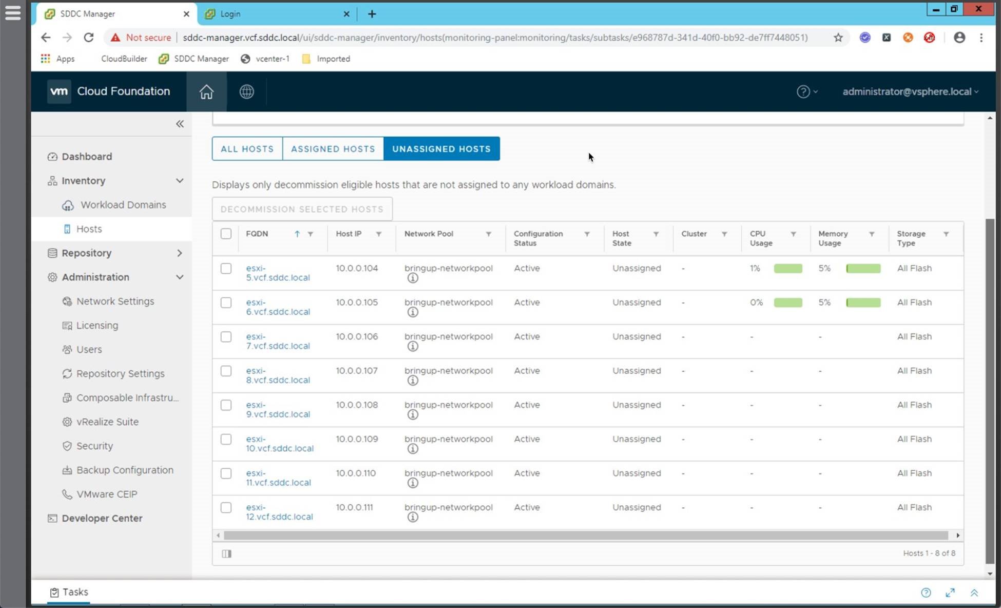
Download Software Bundles
Prior to deploying the VI domain you must download the NSX-T install bundle. In addition, prior to deploying Enterprise PKS, you must download the PKS install bundle.
Bundles can be downloaded in one of two ways:
1. Download the bundle from the VCF Software Repository. Requires the SDDC Manager have access to the repository. To do this, once you have verified WAN access to the repository, register your MyVMware credentials in the SDDC Manager (link to demo). Download the Enterprise PKS bundle when it becomes available (link to demo).
2. Use the Offline Bundle Transfer tool to retrieve the bundle and manually upload it to the
SDDC Manager. (see https://docs.vmware.com/en/VMware-Cloud-Foundation/3.9/vcf-39-upgrade/G…-
47DA-845E-E0863094F7B0.html?hWord=N4IghgNiBcIPYDMEQJYDsCmACARgVzQBMJsAXAJzDQGcENyQBfIA)
Note that you must download the software bundles that are applicable to the version of VCF you are running. It is recommended that install bundles be downloaded using the SDDC Manager.
Prerequisites:
• A valid “MyVMware” account entitled to download Cloud Foundation
• Option 1: SDDC Manager must have access to the Cloud Foundation depot (verify firewall ports)
• Option 2: Download the Offline Bundle Utility (https://docs.vmware.com/en/VMwareCloud-Foundation/3.9/vcf-39-upgrade/GU…-
E0863094F7B0.html?hWord=N4IghgNiBcIEYFcB2ATCBTABAgLgSwjxwE8QBfIA)
The estimated time to complete this task is 30 mintes. Download times will vary based on bandwidth. Note that the NSX-T and PKS bundles are ~10GB in size.
Procedure:
The procedure below shows how to download the bundles using the SDDC Manager UI. For the offline bundle refer to the documentation.
• https://storagehub.vmware.com/t/vmware-cloud-foundation/lifecycle-manag…
Notes:
By default the SDDC Manager checks the public repository once each hour. It may take several cycles before the install bundles become available.
Cloud Foundation 3.9.x only allows for one active bundle download at a time. As such you will need to download each bundle separately.
Bundles can be large (i.e. over 10GB). Plan adequate time to allow the bundles to be downloaded.
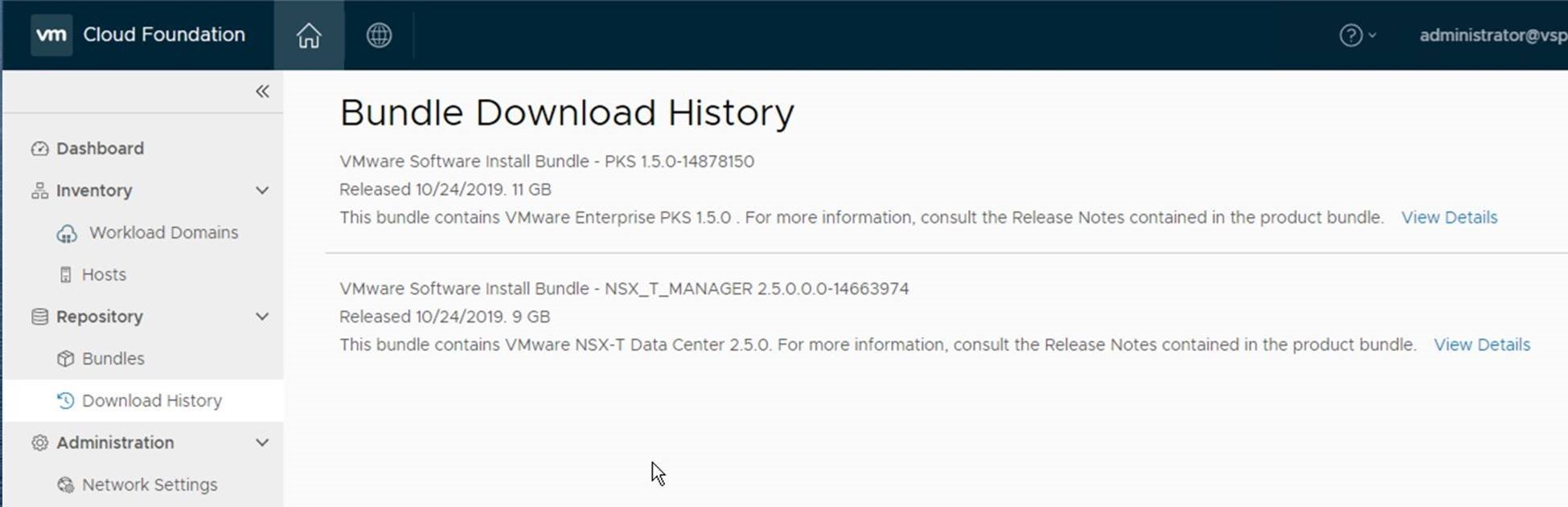
The screen shot below shows an example from VCF 3.9.1 where we see the NSX-T and PKS installation bundles have been downloaded.
Install NSX-T License
You must add a valid NSX-T license to the SDDC Manager license inventory prior to creating the VI domain that will provide the virtual infrastructure for Enterprise PKS.
During Domain creation the license keys from the Cloud Foundation license inventory are assigned for the vSphere, vSAN and NSX components. The licenses for vSphere and vSAN are loaded to the SDDC Manager inventory during bring up, the NSX-T license must be added post bring-up.
Prerequisites:
A valid NSX-T license (edition may vary)
The estimated time to complete this task is 5 minutes.
Procedure:
• https://storagehub.vmware.com/t/vmware-cloud-foundation/sddc-managerope…
The screenshot below shows an example of the SDDC Manager license page. Note the license keys have been removed in this example.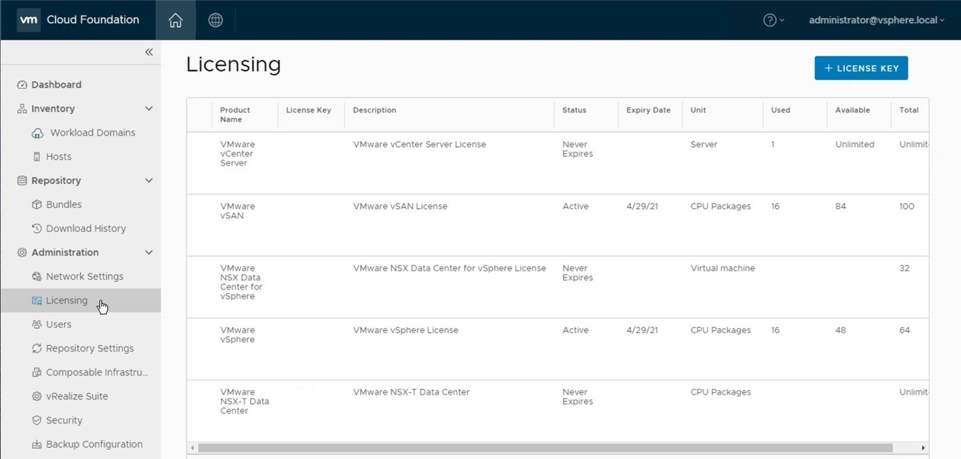
Create NSX-T backed VI Domain
In Cloud Foundation, Enterprise PKS is a solution that gets installed on top of an existing VI domain. The VI domain must be created with NSX-T.
Use the SDDC Manager to deploy a VI Domain on which you will install Enterprise PKS.
Note: For VCF on VxRail, consult with Dell EMC to have them create the VI domain. The procedure for ReadyNodes is outlined below:
Perquisites:
• Verify the NSX-T Software Bundle has been downloaded
• Verify the NSX-T License has been added to the SDDC Manager
• Verify free hosts are available in the free pool
• Create a network pool for the new VI Domain
• Assign IP addresses for the vCenter Server and NSX-T Manager instances and add these to DNS with both reverse and forward lookup records. Values used in this example:
o vCenter Server IP: 172.17.31.21 o NSX-T Manager Virtual IP: 172.17.31.22 o NSX-T Manager Node 1 IP: 172.17.31.23 o NSX-T Manager Node 2 IP: 172.17.31.24 o NSX-T Manager Node 3 IP: 172.17.31.25
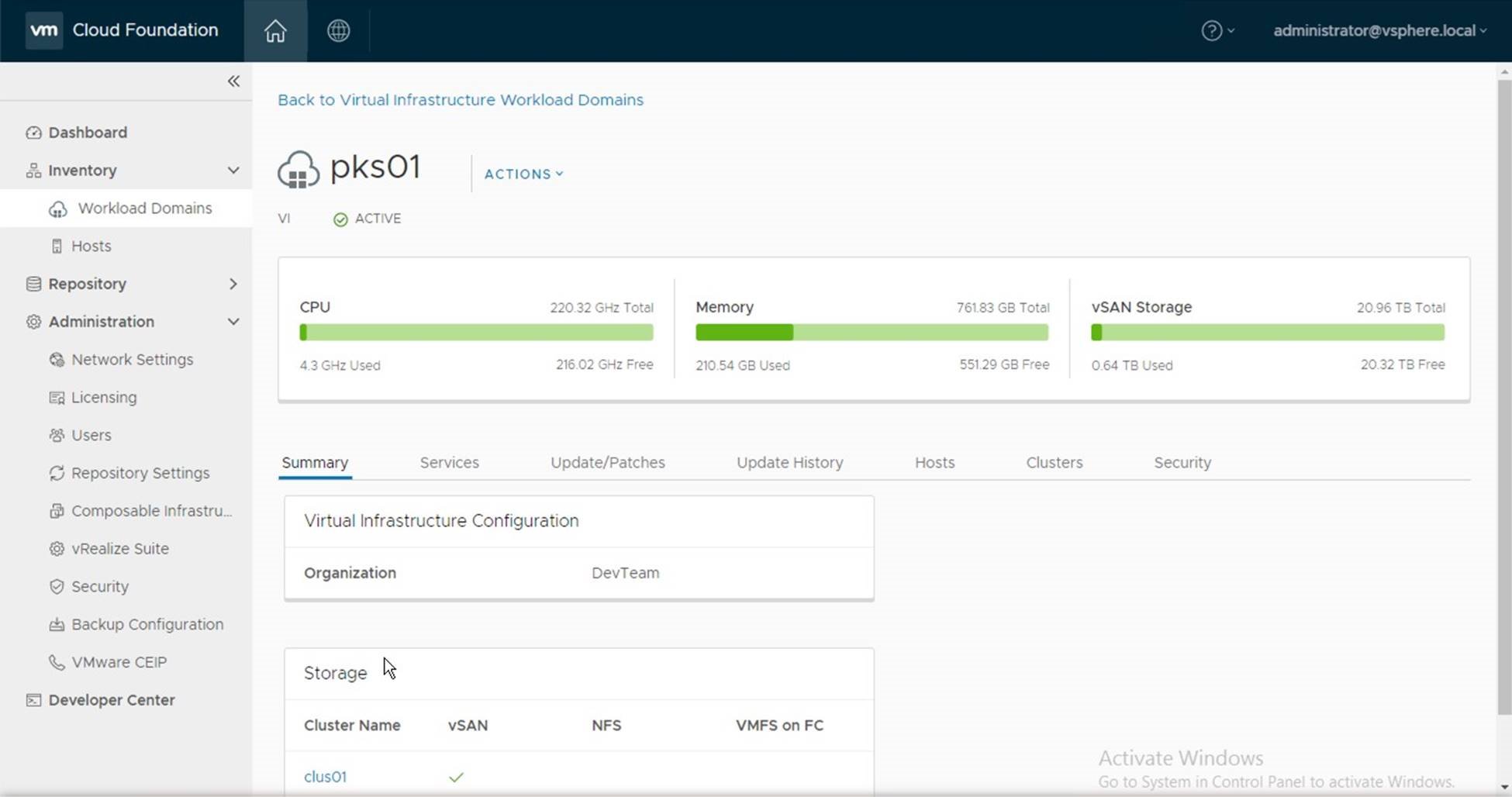
• Choose a name for the domain and cluster.
o VI Domain Name: pks01 o VI Domain Cluster Name: clus01 o VI Domain Organization Name: DevTeam
Note: Is recommended that you run the “./sos --health-check” from the SDDC Manager prior to creating the VI Domain to verify there are no alarms or alerts in VCF.
The estimated time to complete this task is 120 minutes.
Procedure:
• https://storagehub.vmware.com/t/vmware-cloud-foundation/workload-domain…
After creating the VI domain, login to the vCenter Server instance and clear any alerts/alarms.
The screenshot below shows the new VI Domain in the SDDC Manager UI.
NSX-T Environment Preparation
After creating the VI Domain, and prior to deploying the Enterprise PKS solution, you must configure NSX-T for use with Enterprise PKS.
This is a manual effort in VCF 3.9.x and includes performing the following tasks:
• Creating three uplink profiles for the Edge Transport Nodes
• Creating two uplink transport zones for the Edge Transport Nodes
• Creating nine segments (i.e. logical switches)
• Deploying two edge transport nodes
• Creating an edge cluster
• Creating a tier-0 logical router
• Creating a tier-1 logical router
• Creating an IP block for the K8s Nodes and Pods
• Creating an IP Pool for the K8s load balancer
The section that follows provides the steps to accomplish these tasks.
Creating Uplink Profiles
Edge nodes have four interfaces:
• The first interface connects to the edge node to the vSphere management network.
• The second interface connects the edge node to the Geneve overlay network, enabling it to participate as a TEP in the overlay network along with the ESXi hosts.
• The third interface connects the edge node to the first Top-of-Rack (ToR) switch.
• The fourth interface connects to the edge node to the second ToR switch. For each interface type an uplink profile must be created in NSX.
An uplink profile is needed for the interface that will connect the Edge Node to the overlay (geneve) network. Two additional uplink profiles are needed, one for each of the uplink interfaces that will connect the Edge Node to the upstream network.
Prerequisites:
• Assign three VLAN IDs, one for each Edge uplink profile
• Jumbo frames must be enabled in the physical network that will be used for the overlay network. (we will set the MTU for the geneve overlay profile to 9000 in this example)
• (optional) Set the MTU for the two uplink profiles to 9000
Values used in this example:
|
Uplink Name |
Active Uplink |
VLAN |
MTU |
|
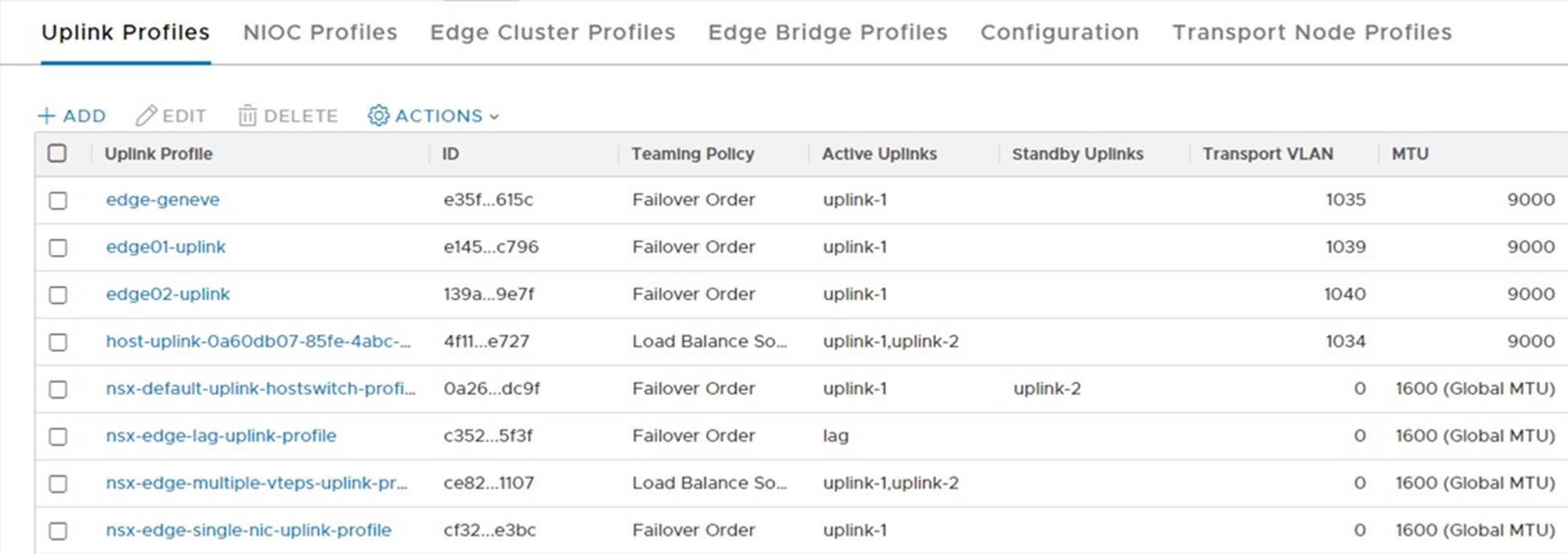
edge-geneve |
uplink-1 |
1035 |
9000 |
|
edge-uplink01 |
uplink-1 |
1039 |
9000 |
|
edge-uplink02 |
uplink-2 |
1040 |
9000 |
The estimated time to complete this task is 10 minutes.
Procedure:
• https://storagehub.vmware.com/t/vmware-cloud-foundation/enterprise-pks-…
The screenshot below shows the list of uplink profiles created:
Create Transport Zones
NSX transport zones define the boundary over which transport nodes can communicate. For the edge nodes to communicate with the upstream ToR switches two transport zones must be created on the correct VLANs.
Prerequisites:
• Assign a name for each transport zone.
Values used in this example:
|
Transport Name |
NVDS Name |
Traffic Type |
|
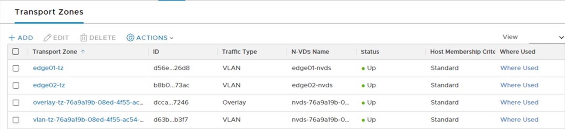
edge01-tz |
edge01-nvds |
VLAN |
|
edge02-tz |
edge02-nvds |
VLAN |
The estimated time to complete this task is 5 minutes.
Procedure:
• https://storagehub.vmware.com/t/vmware-cloud-foundation/enterprise-pks-…
The screenshot below shows the list of transport zones created:
Create Segments
NSX segments, also known as logical switches, represent isolated L2 networks that are abstracted from the underlying physical network. Segments can participate in either VLAN or overlay traffic flows.
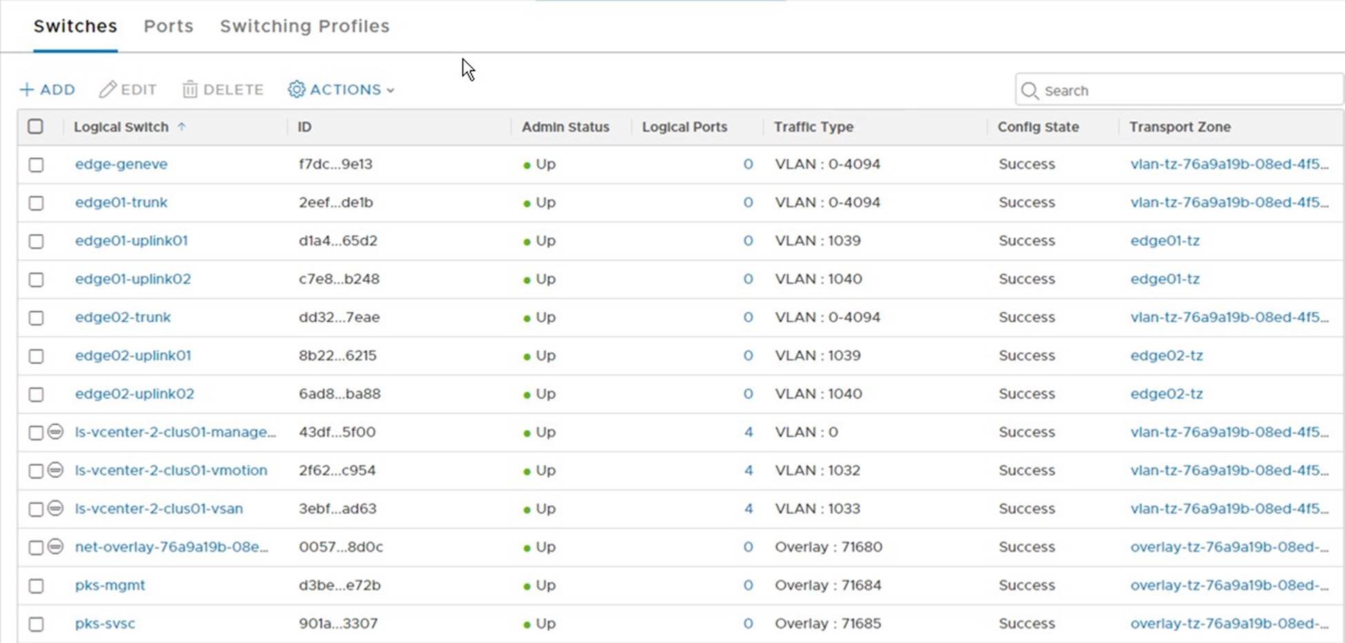
A total of nine segments need to be created. Seven for the Edge Transport Nodes and two for the Enterprise PKS logical networks:
Prerequisites:
• Assign a name for each segment
• Assign VLAN IDs the VLAN based segments
Values used in this example:
|
Segment Name |
Type |
Assigned Transport Zone |
Assigned VLAN |
|
ls-edge01-uplink01 |
VLAN |
edge01-tz |
1039 |
|
ls-edge01-uplink02 |
VLAN |
edge01-tz |
1040 |
|
ls-edge02-uplink01 |
VLAN |
edge01-tz |
1039 |
|
ls-edge02-uplink02 |
VLAN |
edge02-tz |
1040 |
|
ls-edge01-trunk |
Trunk |
vlan-tz-<id> |
0-4094 |
|
ls-edge02-trunk |
Trunk |
vlan-tz-<id> |
0-4094 |
|
ls-edge01-geneve |
Overlay |
vlan-tz-<id> |
0-4094 |
|
ls-pks-mgmt |
Overlay |
overlay-tz-<id> |
n/a |
|
ls-pks-svsc |
Overlay |
overlay-tz-<id> |
n/a |
The estimated time to complete this task is 15 minutes.
Procedure:
• https://storagehub.vmware.com/t/vmware-cloud-foundation/enterprise-pks-…
The screenshot below shows the list of segments (logical switches) created:
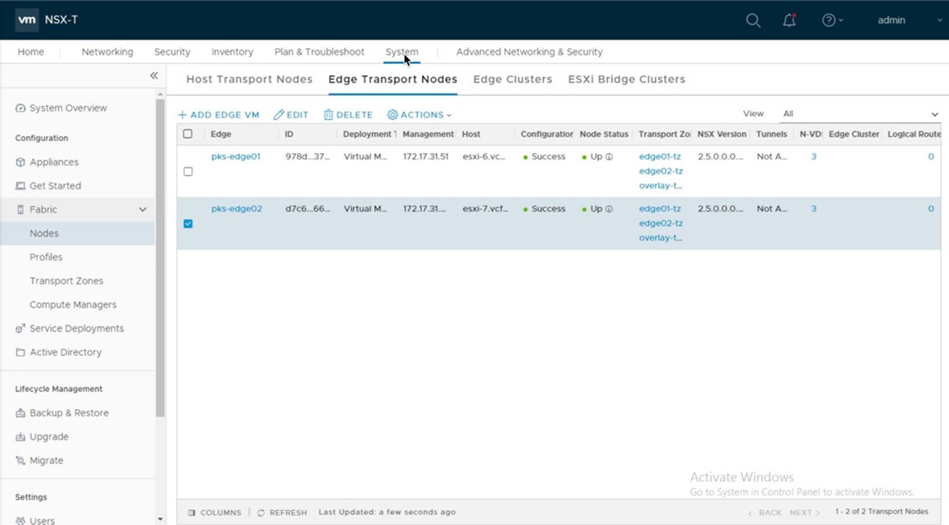
Deploy Edge Nodes
NSX Edge nodes provide routing services and external network connectivity to workloads running on the transport zones and segments. Prior to deploying Enterprise PKS, you must deploy two edge nodes and configure them as an active/passive pair in an edge cluster.
Notes:
Due to a bug in the NSX-T UI, this procedure shows deploying the Edge Nodes from the OVA file in lieu of using the UI.
Enterprise PKS leverages the logical load balancer which requires the edge’s node be deployed using the large configuration profile.
Prerequisites:
• Assign a management IP on the vSphere Management network for each edge node.
• Assign a DNS name to each edge node.
Values used in this example:
|
Edge Node Name |
Management IP |
|
|
|
pks-edge01 |
172.17.31.51/24 |
|
|
|
pks-edge02 |
172.17.31.52/24 |
|
|
The estimated time to complete this task is 30 minutes.
Procedure:
1. https://storagehub.vmware.com/t/vmware-cloud-foundation/enterprise-pks-…
The screenshot below shows the list of deployed Edge Nodes:
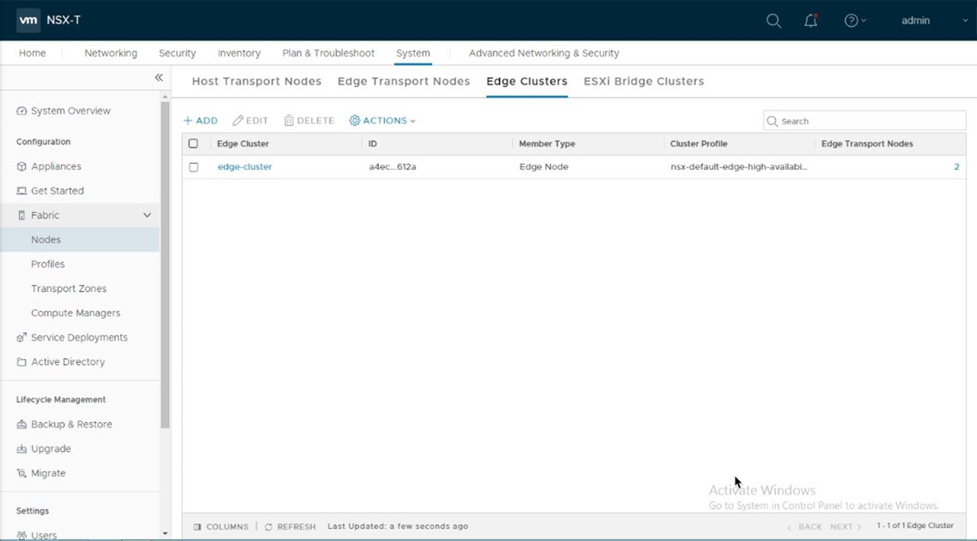
Create an Edge Cluster
You must associate the edge nodes with an edge cluster. An NSX-T edge cluster is a logical grouping of edge transport nodes that provides for high availability of the tier-0 and tier-1 router and other stateful services provided by the edge nodes.
Note: Enterprise PKS requires the edge nodes be configured as “active/passive” pair.
Prerequisites:
• An Edge Cluster Profile Defined
• A name for the edge cluster
• Two deployed edge nodes
Values used in this example:
|
Edge Cluster Name |
Edge Cluster Type |
Edge Cluster Members |
|
|
Edge-cluster |
Active/passive |
pks-edge01 pks-edge02 |
|
The estimated time to complete this task is 5 minutes.
Procedure:
• https://storagehub.vmware.com/t/vmware-cloud-foundation/enterprise-pks-…
The screenshot below is an example of the edge-cluster in the NSX-T UI:
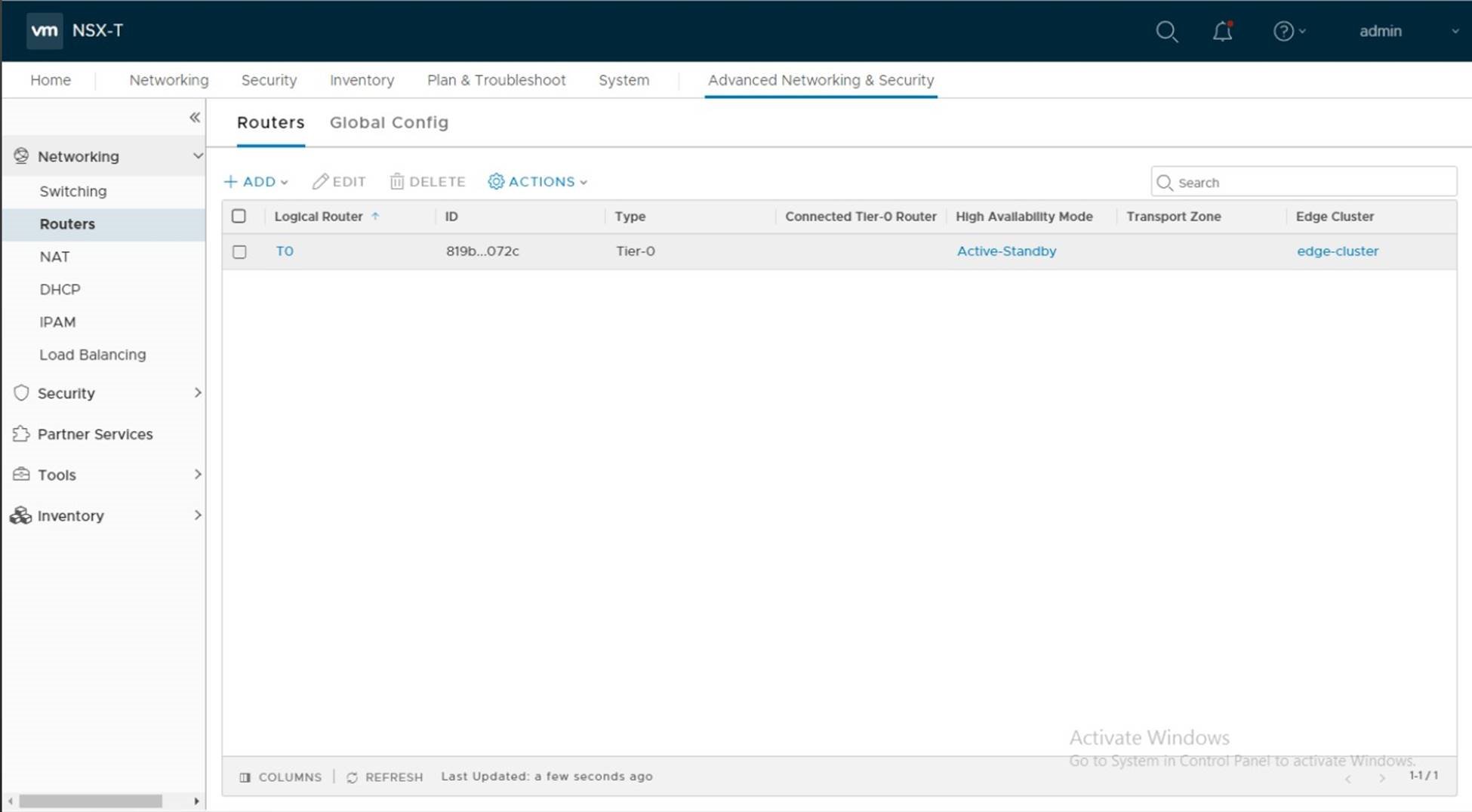
Configure Tier 0 Router
A Tier 0 (tier zero) router is an NSX-T logical router that reproduces routing functionality in a virtual environment. Tier 0 routers are completely decoupled from underlying hardware.
In an Enterprise PKS deployment on VMware Cloud Foundation the tier-0 logical router provides an egress and ingressgateway service between the K8s components running on the logical network and the physical network.
Prerequisites:
• An Edge Cluster containing two edge nodes
• BGP enabled on the Top-of-Rack Switches
• A name for the tier-0 router
• IP addresses for the tier-0 router uplinks
Note:
When configuring the tier 0 router, use the “Advanced Network & Security” tab. From the PKS 1.4 Release Notes (https://docs.pivotal.io/pks/1-4/release-notes.html):
NSX-T v2.4 introduced a new Policy API and a new NSX Manager user interface
(UI) based on the Policy API. However, Enterprise PKS does not support the
Policy API or Policy-based UI. Enterprise PKS supports the NSX Management
API, which is exposed via the “Advanced Networking” tab of the of the NSX
Manager UI. When installing and configuring NSX-T for use with Enterprise PKS, use the “Advanced Networking and Security” tab to create any required networking objects.
Values used in this example:
|
Name |
Uplink Interfaces |
Assigned IPs |
BGP AS Number |
|
T0 |
Edge01-uplink01 Edge01-uplink02 Edge02-uplink01 Edge02-uplink02 |
172.17.39.5 172.17.40.5 172.17.39.6 172.17.40.6 |
64702 |
|
BGP Neighbors |
|
172.17.39.1 172.17.40.1 |
64701 |
Estimated time to complete this task is 5 minutes.
Procedure:
• https://storagehub.vmware.com/t/vmware-cloud-foundation/enterprise-pks-…
The screenshot below is an example of the tier 0 router.
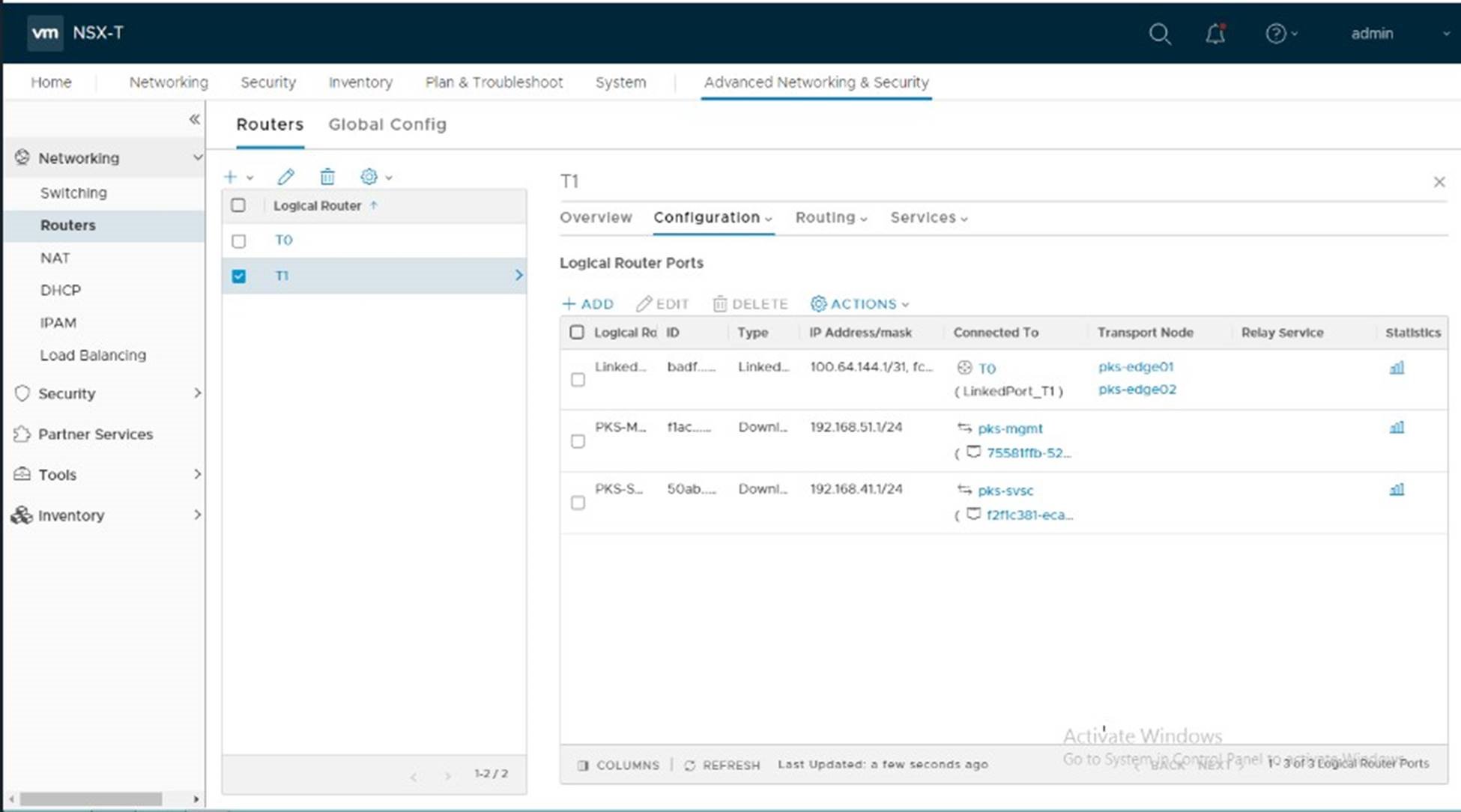
Configure Tier 1 Router
An NSX-T logical router reproduces routing functionality in a virtual environment completely decoupled from underlying hardware. Tier-1 logical routers have downlink ports to connect to NSX-T logical switches and uplink ports to connect to NSX-T tier-0 logical routers.
In an Enterprise PKS deployment on VMware Cloud Foundation the tier-1 logical routers provide routing access to the logical switches used by PKS as well as load balancing services for deployed K8s clusters.
You must manually deploy the first tier-1 router and link it to the tier-0 router.
Prerequisites:
• A tier-0 router
• A logical switch for the PKS Management plane (pks-mgmt)
• A logical switch for the PKS Control plane (pks-svsc)
• A name for tier-1 router
• IP addresses for the PKS Management and Service networks
Note:
When configuring the tier-1 router, use the “Advanced Network & Security” tab. From the PKS 1.4 Release Notes (https://docs.pivotal.io/pks/1-4/release-notes.html):
NSX-T v2.4 introduced a new Policy API and a new NSX Manager user interface
(UI) based on the Policy API. However, Enterprise PKS does not support the
Policy API or Policy-based UI. Enterprise PKS supports the NSX Management
API, which is exposed via the “Advanced Networking” tab of the of the NSX
Manager UI. When installing and configuring NSX-T for use with Enterprise PKS, use the “Advanced Networking and Security” tab to create any required networking objects.
Values used in this example:
|
Name |
Uplink Interfaces |
Assigned IPs |
|
|
T1 |
|
|
|
|
pks-mgmt |
|
192.168.5.1/24 |
|
|
pks-svsc |
|
192.168.41.1 |
|
Estimated time to complete this task is 5 minutes.
Procedure:
• https://storagehub.vmware.com/t/vmware-cloud-foundation/enterprise-pks-…
The screenshot below is an example of the tier 0 router.
Setup IP Dynamic Address Management for Enterprise PKS
As K8s clusters and pods are created, Enterprise PKS will dynamically assign IP address for the nodes & pods. In addition, a new tier-1 router is deployed to pass egress & ingress traffic in and out of the K8s clusters, as well as provide load balancing services.
To facilitate IP address management in Enterprise PKS and facilitate the dynamic creation and deletion of K8s clusters, IP Blocks are reserved for the nodes and pods and an IP Pool is defined for the routable IPs used for the load balancer.
Prerequisites:
• IP Range assigned for the Node Block: 30.0.0.0/16
• IP Range assigned for the Pod Block: 20.0.0.0/16
• IP range assigned for the IP Pool
• Names to be assigned to the IP blocks and pool
Note:
When configuring IP Blocks and IP Pools, use the “Advanced Network & Security” tab. From the PKS 1.4 Release Notes (https://docs.pivotal.io/pks/1-4/release-notes.html):
NSX-T v2.4 introduced a new Policy API and a new NSX Manager user interface
(UI) based on the Policy API. However, Enterprise PKS does not support the
Policy API or Policy-based UI. Enterprise PKS supports the NSX Management
API, which is exposed via the “Advanced Networking” tab of the of the NSX
Manager UI. When installing and configuring NSX-T for use with Enterprise PKS, use the “Advanced Networking and Security” tab to create any required networking objects.
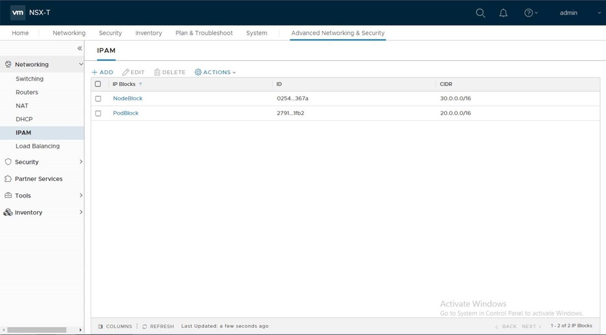
Values used in this example:
|
Component |
Value |
Name |
Notes |
|
Node Block |
30.0.0.0/16 |
NodeBlock |
Note the use of the ‘/16’ CIDR |
|
Pod Block |
20.0.0.0/16 |
PodBlock |
Note the use of the ‘/16’ CIDR |
|
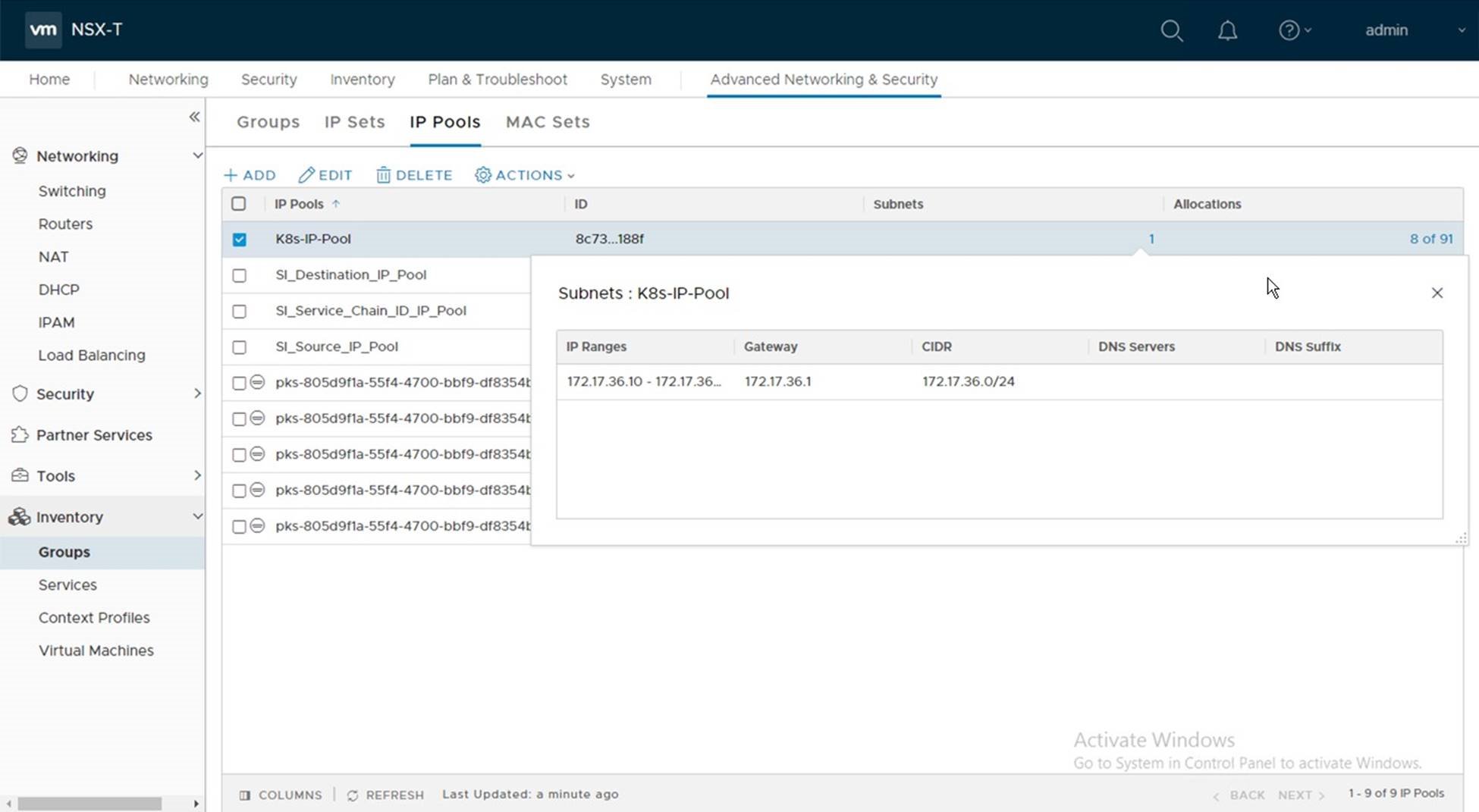
IP Pool |
172.17.36.10 – 100 |
K8s-LB-Pool |
Must be routable |
Estimated time to complete this task is 5 minutes.
Procedure:
• https://storagehub.vmware.com/t/vmware-cloud-foundation/enterprise-pks-…
The screenshots below show the configured IP Blocks and IP Pool:
IP Blocks:
IP Pools:
Create Resource Pools
In large deployments, K8s clusters are distributed across multiple clusters. This helps to ensure resiliency by protecting against failures. In small deployments (i.e. test/dev/poc) where Enterprise PKS will be deployed on a single cluster, vSphere Resource Pools need to be created on the cluster in the vSphere web client. These resource pools are used to represent the PKS Availability Zones (AZs).
Note, a minimum of two AZs are required, one for management and one for compute. In this example we will use four. One for Management and three for compute.
Prerequisites:
• VI Domain Created with one vSphere cluster
• A name for the Resource Pools
Values used in this example:
|
Resource Pool Name |
Role |
|
MGMT-AZ |
Management Availability Zone |
|
AZ01 |
Compute Availability Zone |
|
AZ02 |
Compute Availability Zone |
|
AZ03 |
Compute Availability Zone |
Estimated time to complete this task is 5 minutes.
Procedure:
• https://storagehub.vmware.com/t/vmware-cloud-foundation/enterprise-pks-…
The screenshot below shows the Resource Pools defined: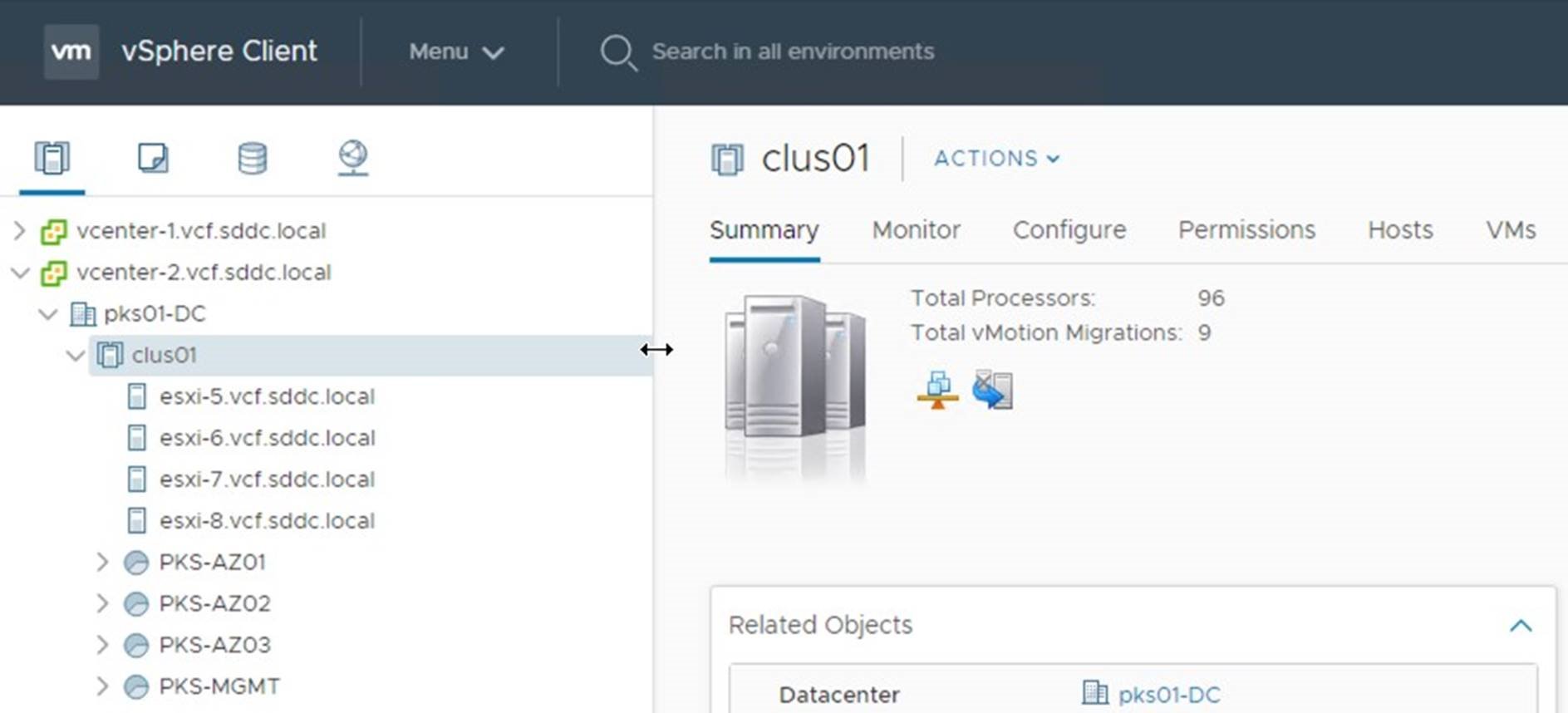
Add DNS entries for the Enterprise PKS components
Prerequisites:
• FQDN assigned for each of the four management components
• IP address to be assigned to each
• Available DNS server
Values used in this example:
|
Component |
DNS Name |
IP Address |
|
|
Operations Manager |
opsman.vcf.sddc.local |
192.168.51.10 |
|
|
Bosh Director |
bosh.vcf.sddc.local |
192.168.51.11 |
|
|
PKS Control Plane |
pks.vcf.sddc.local |
192.168.51.12 |
|
|
Harbor |
harbor.vcf.sddc.local |
192.168.51.13 |
|
Estimated time to complete this task is 5 minutes.
Note on PKS Deployment topologies.
Enterprise PKS can be deployed using three different deployment topologies.
• NAT
• No-NAT
• Hybrid
VMware Cloud Foundation 3.9.x supports deploying Enterprise PKS using the No-NAT topology. This design requires that Management Plane network, Control Plane network, and K8s management and service networks be routable. Refer to the PKS documentation for more information on the No-NAT deployment topology implemented by Cloud Foundation.
Refer to the Installing Pivotol PKS 1.5 Installation guide (https://docs.pivotal.io/pks/1-4/nsxttopologies.html) for a description of the supported Pivotal PKS deployment topologies.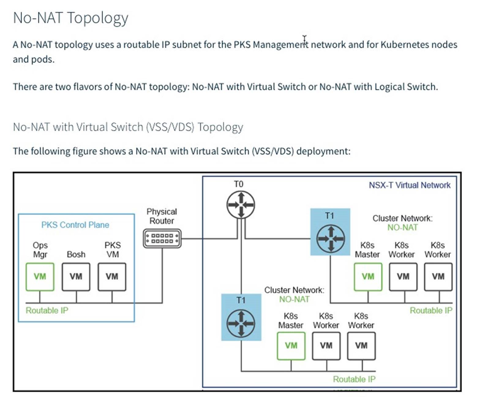
Deploy Enterprise PKS
Enterprise PKS is a solution deployed on-top of an existing VI domain. The deployment of Enterprise PKS is fully automated using the VMware SDDC Manager. During the deployment the SDDC Manager deploys the PKS Operations Manager, Bosh Director, PKS API, and optionally the Harbor Container Registry.
Prerequisites:
• A VI Domain created with NSX-T
• The Enterprise PKS Install Bundle downloaded to the SDDC Manager
• An NSX Edge Cluster with an associated tier-0 and tier-1 router
• DNS updated with records for the Operations Manager, Bosh Director, PKS API and Harbor Container Registry
Values used in this example:
|
Component |
Name |
IP Address |
|
VI Domain |
pks01 |
|
|
PKS Solution |
pks01 |
|
|
Operations Manager |
opsman.vcf.sdd.local |
192.168.51.10 |
|
Bosh Director |
bosh.vcf.sdd.local |
192.168.51.11 |
|
PKS Control Plane |
pks.vcf.sdd.local |
192.168.51.12 |
|
Harbor Registry |
harbor.vcf.sdd.local |
192.168.51.13 |
|
NSX Edge Cluster |
edge-cluster |
|
|
Tier-0 Router |
T0 |
|
|
Tier-1 Router |
T1 |
|
|
PKS Management Plane Logical Switch |
pks-mgmt |
192.168.51.1/24 |
|
PKS Control Plane Logical Switch |
pks-svsc |
92.168.41.1/24 |
|
Node Block |
NodeBlock |
30.0.0.0/16 |
|
Pod Block |
PodBlock |
20.0.0.0/16 |
|
IP Pool |
K8s-IP-Pool |
172.17.36.10 – 172.17.36.100 |
|
PKS Management Availability Zone |
MGMT-AZ |
|
|
PKS Compute Availability Zone |
AZ01 |
|
|
PKS Compute Availability Zone |
AZ02 |
|
|
PKS Compute Availability Zone |
AZ03 |
|
Estimated time to complete this task is 120 minutes.
Procedure:
• https://storagehub.vmware.com/t/vmware-cloud-foundation/enterprise-pks-…
The screenshot below shows the deployed PKS Solution:
