
Introduction to vSphere Networking
Introduction to vSphere Distributed Switch
This walkthrough is designed to provide an introduction to the VMware vSphere Distributed Switch and the capabilities it enables. Use arrow keys to navigate through the screens.
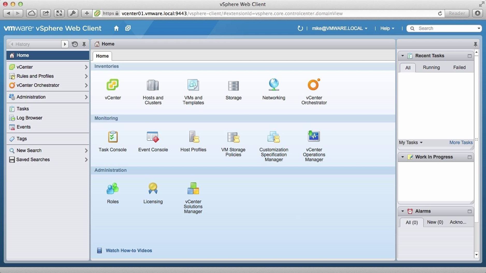
We begin by navigating to the [Hosts and Clusters] view to review the current inventory.
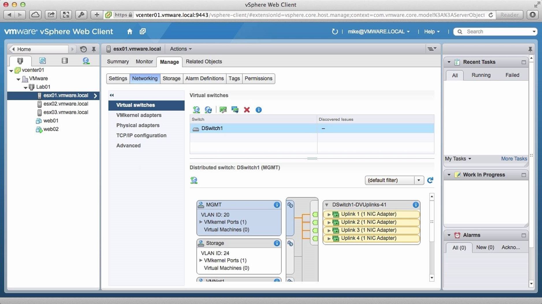
We have already created a distributed switch named DSwitch1 for this demo and all three hosts are attached to it. We also have two virtual machines in the environment. To verify if the hosts have the same uplinks and port groups, we note the hosts and uplinks of the host named esx01-vmware.local and go to the next host named [esx02-vmware.local].
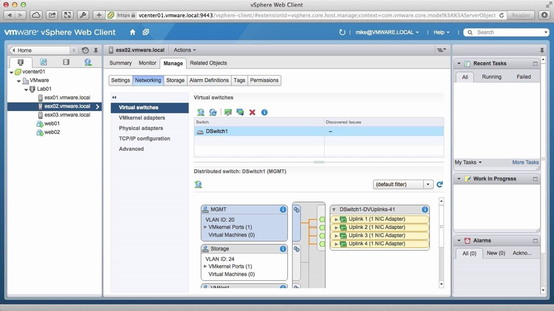
We verify the port groups and uplinks and go to the host named [esx03vmware.local]. Notice that the host is attached to the distributed switch DSwitch1.
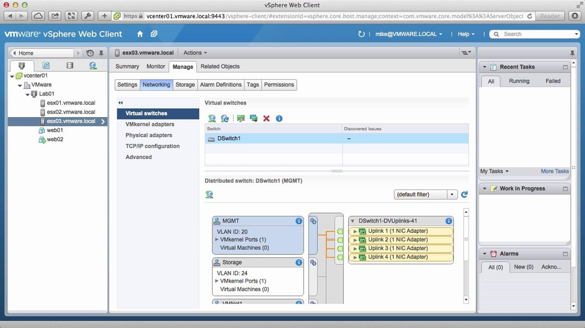
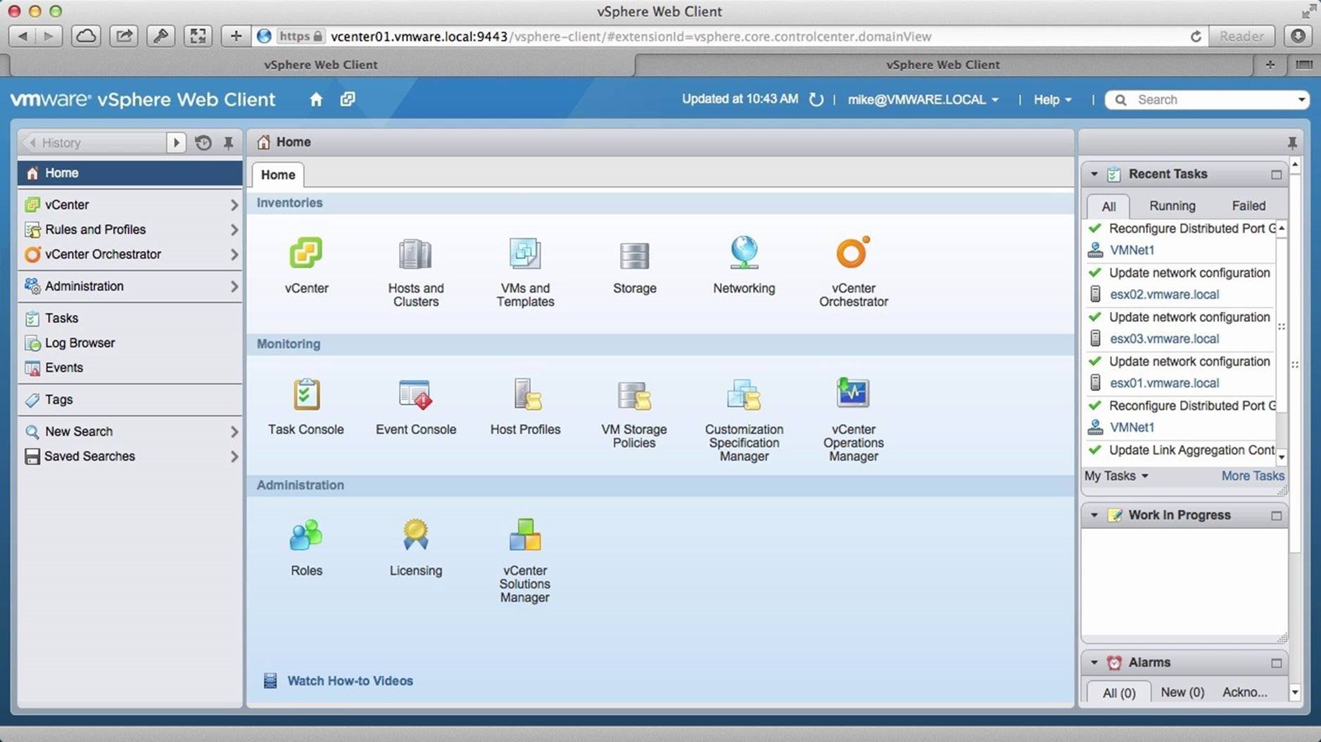
Notice that the port groups and uplinks are the same for this host as well and that it is attached to DSwitch1. Let us now examine the distributed switch itself. To do this, navigate back to the [Home] page.
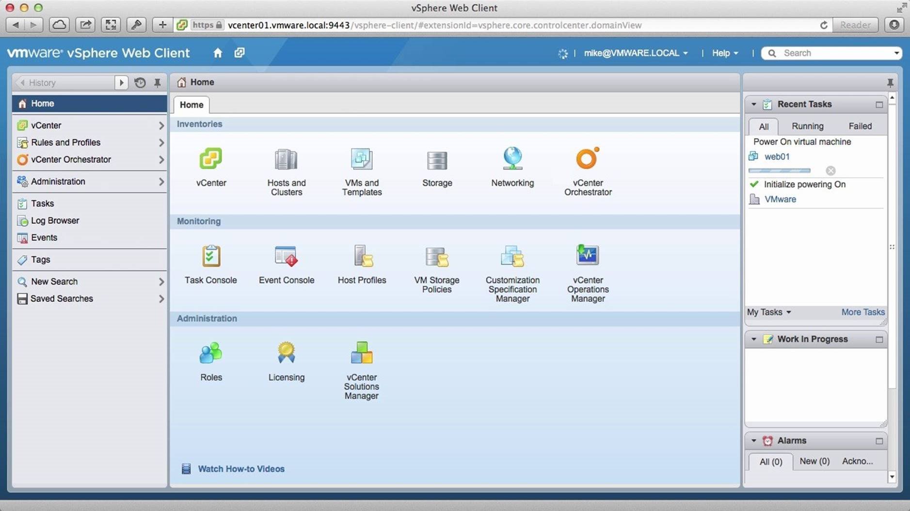
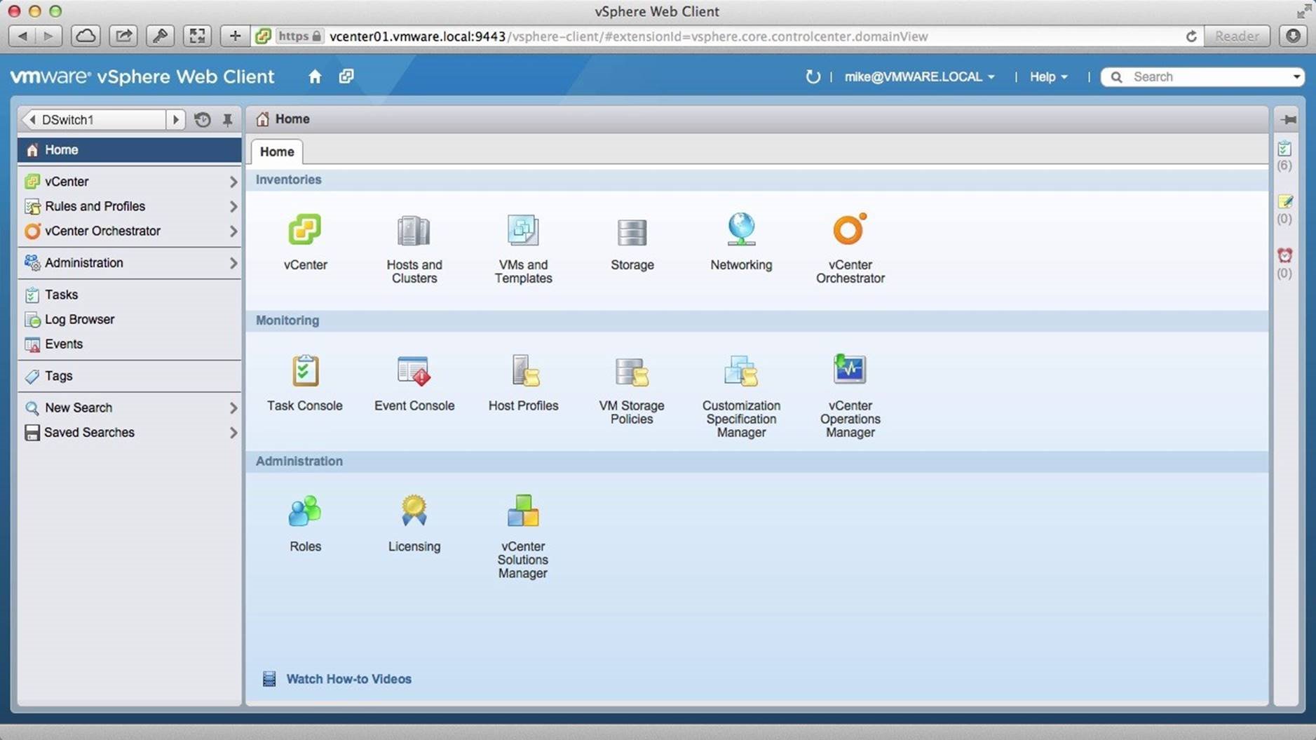
Go to the [Networking] section.
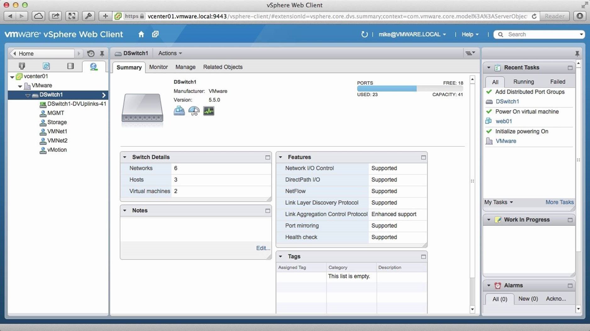
We see our distributed switch, which contains four port groups. Notice that the distributed switch is under the datacenter. This is because vSphere distributed switch is a datacenter object, unlike the standard switch, which is a host object.
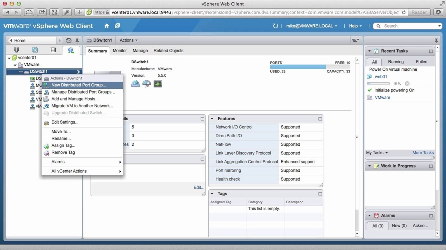
We will now create a new port group to demonstrate how a port group created on the distributed switch is automatically assigned to all hosts that are connected to the distributed switch. We right-click on [DSwitch1] and click on [New Distributed Port Group].
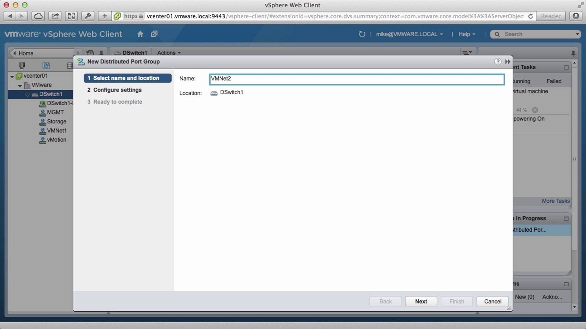
We assign a name to the port group and click on [Next].
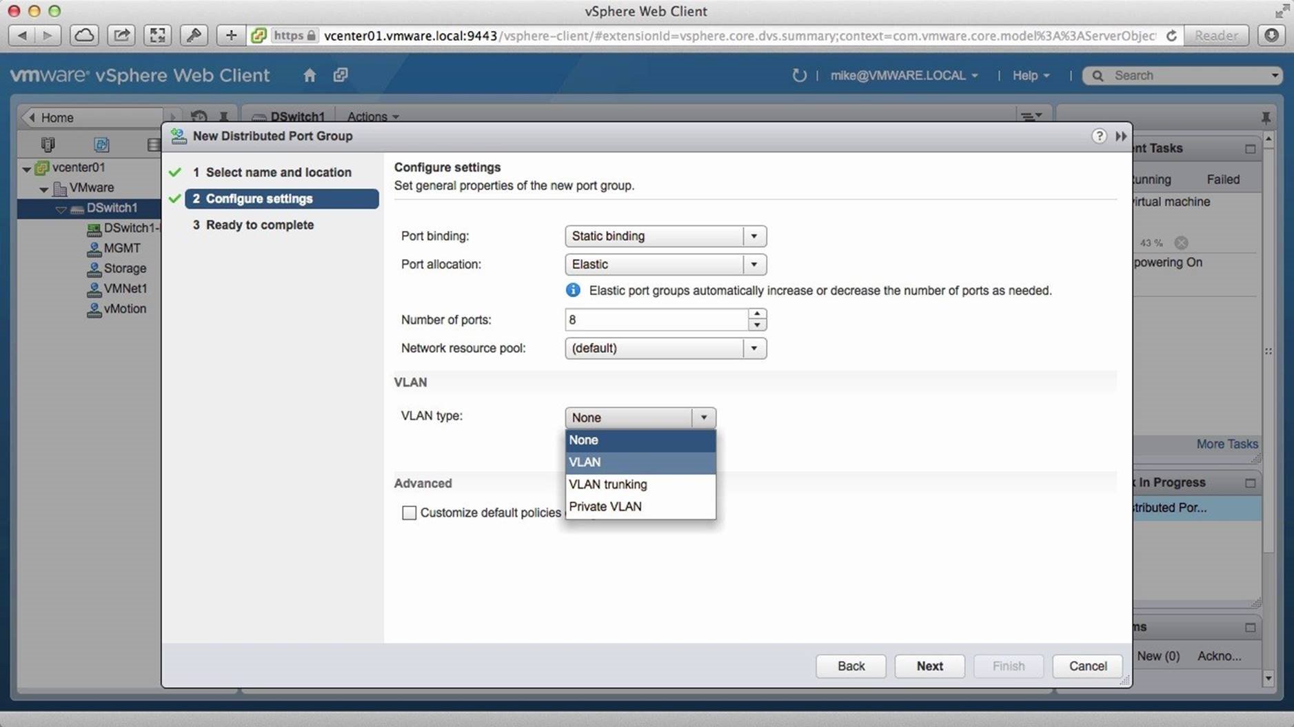
Next we set the VLAN type.
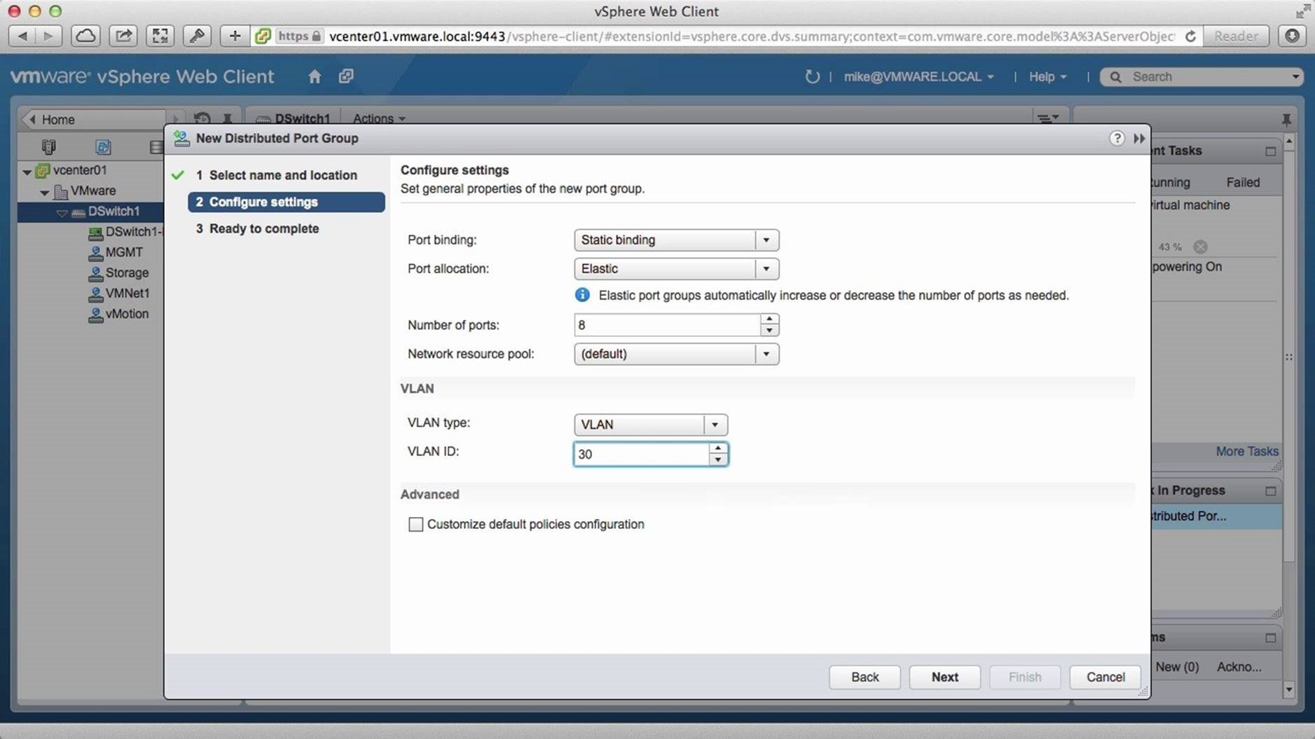
Then specify the VLAN ID and click on [Next].
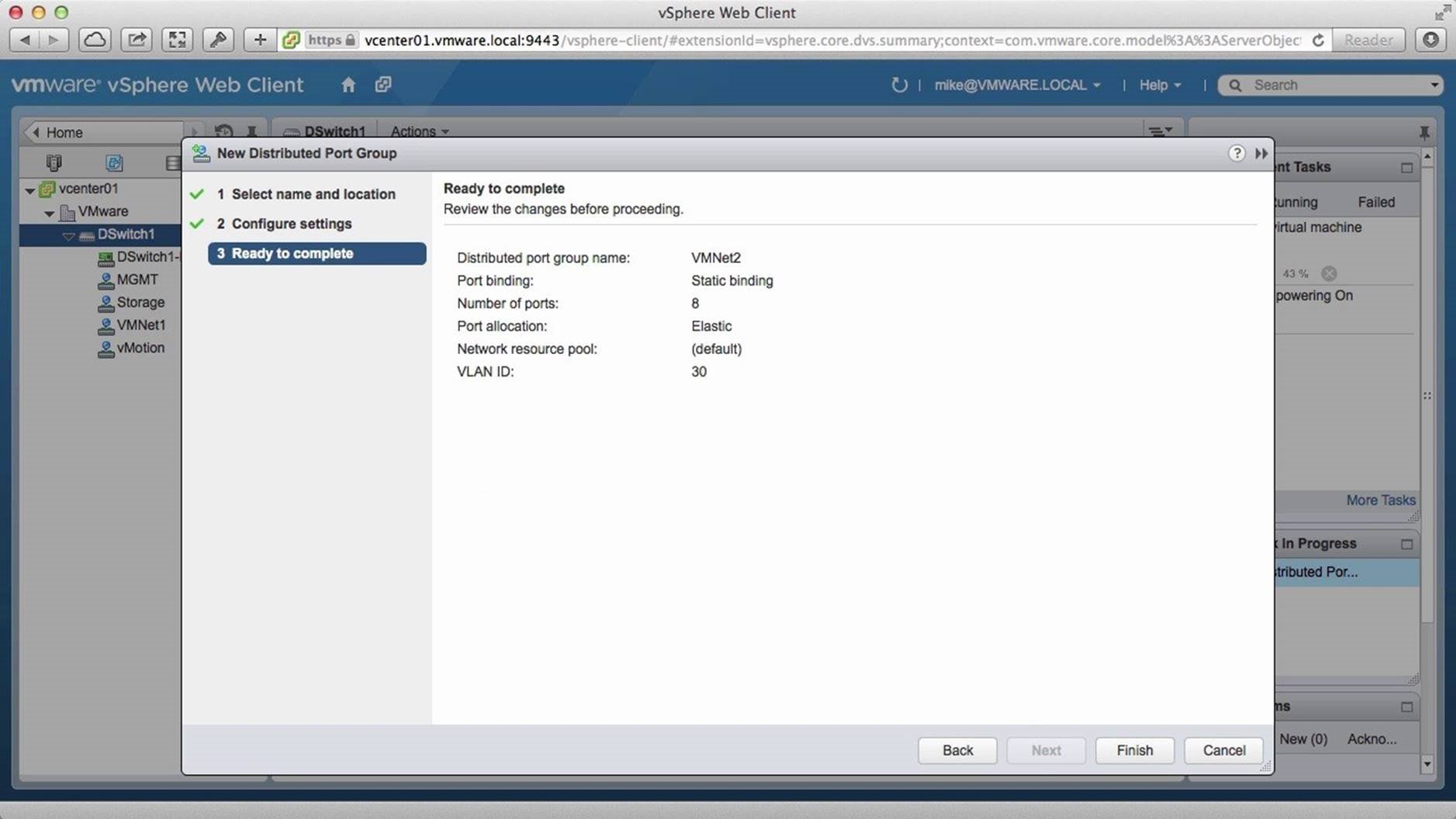
Review the settings and click on [Finish].
The new port group has been created and we see it in the inventory. Since all three hosts in the inventory are connected to the distributed switch, they all automatically have the new port group configuration. To verify this, we go into the newly created port group [VMNet2].
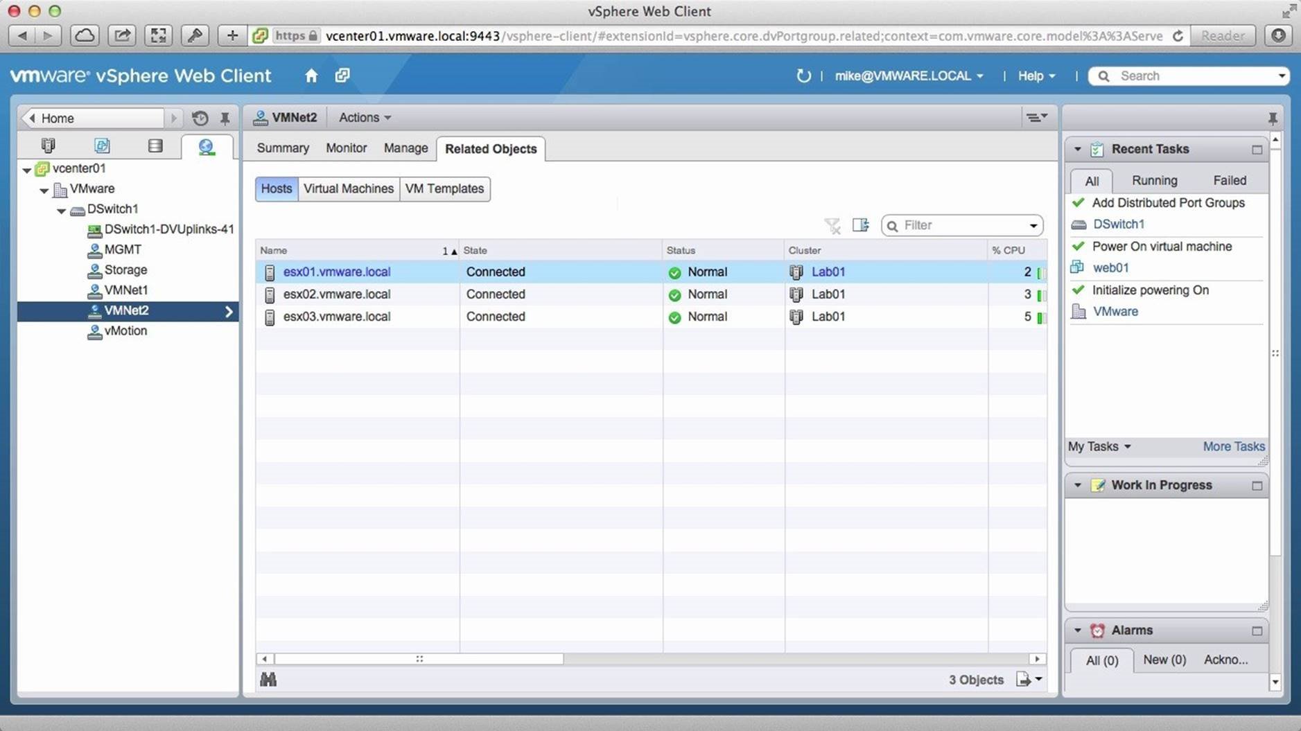
We go to the [Related Objects] tab and see all three hosts are connected to the port group. If we make any changes to this port group, the changes also reflect on all the hosts. This is one of the many benefits of the distributed switch. Next we will demonstrate how to migrate a virtual machine from one network to another on the switch. To do this, we go to [VMNet1].
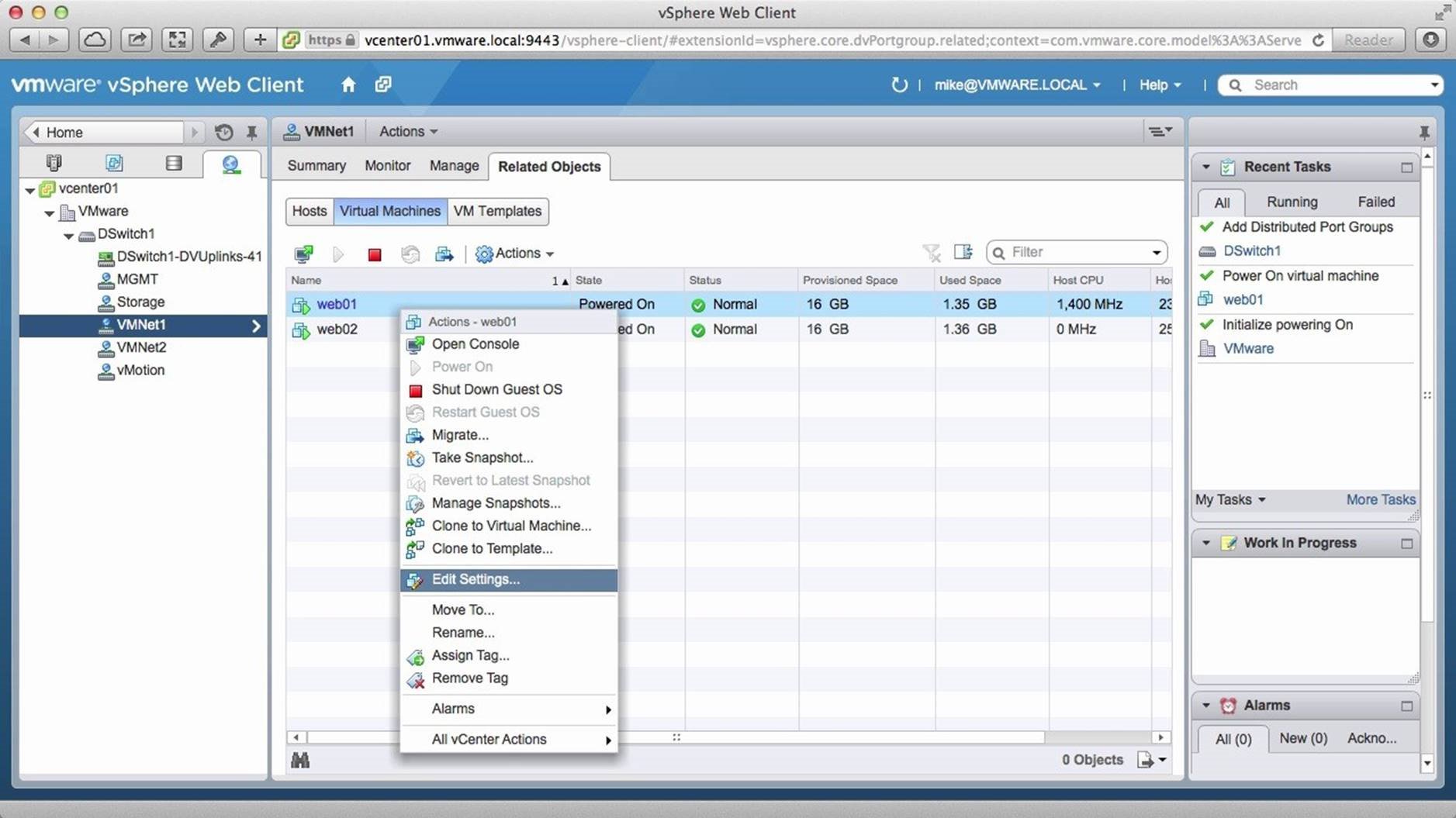
We right-click on the virtual machine [web01] and click on [Edit Settings].
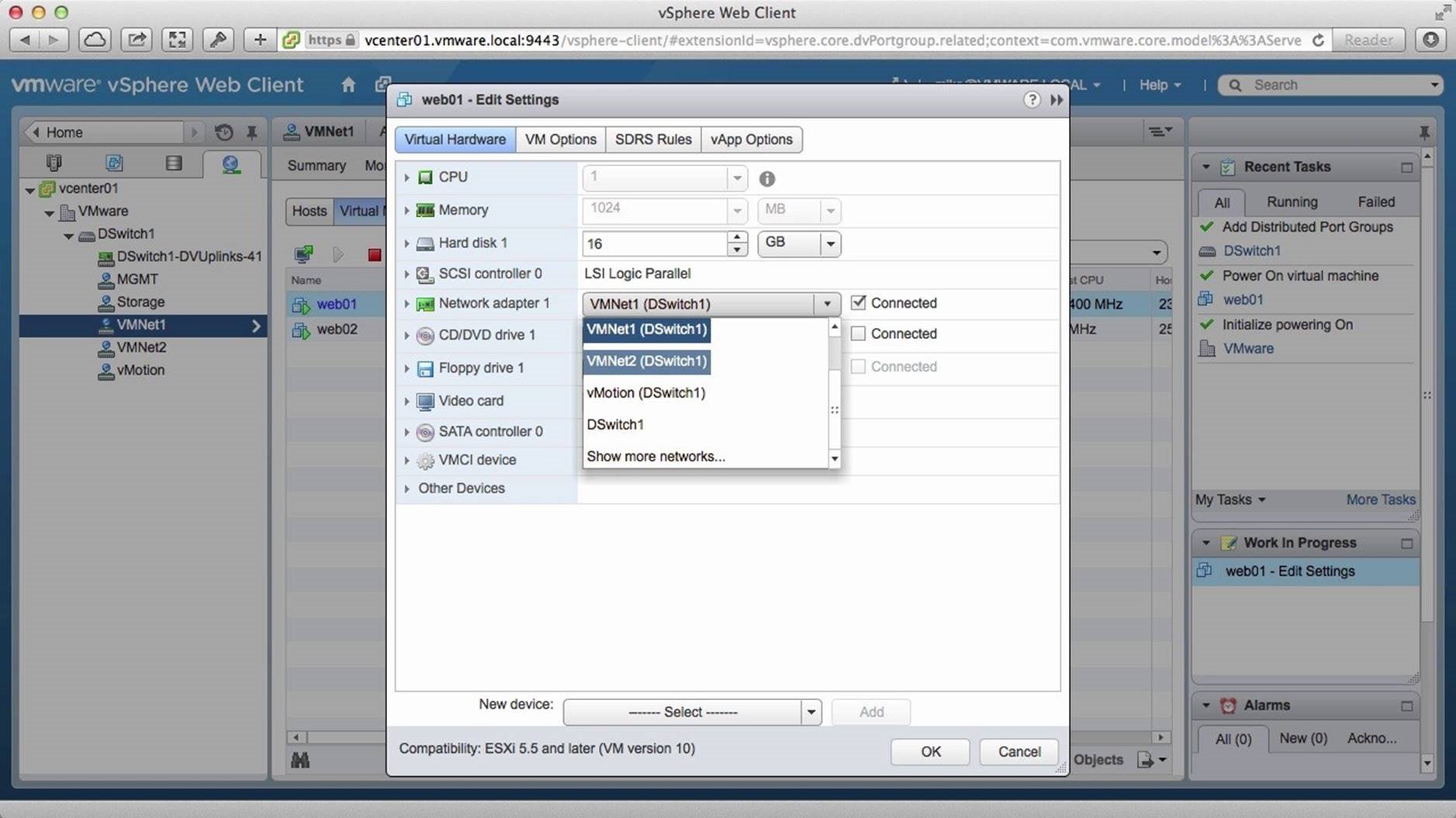
Here, we will move the web01 virtual machine from the VMNet1 network to the VMNet2 network using the Network Adapter drop-down and click on [OK].
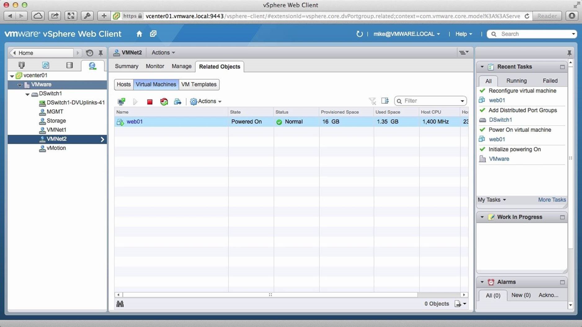
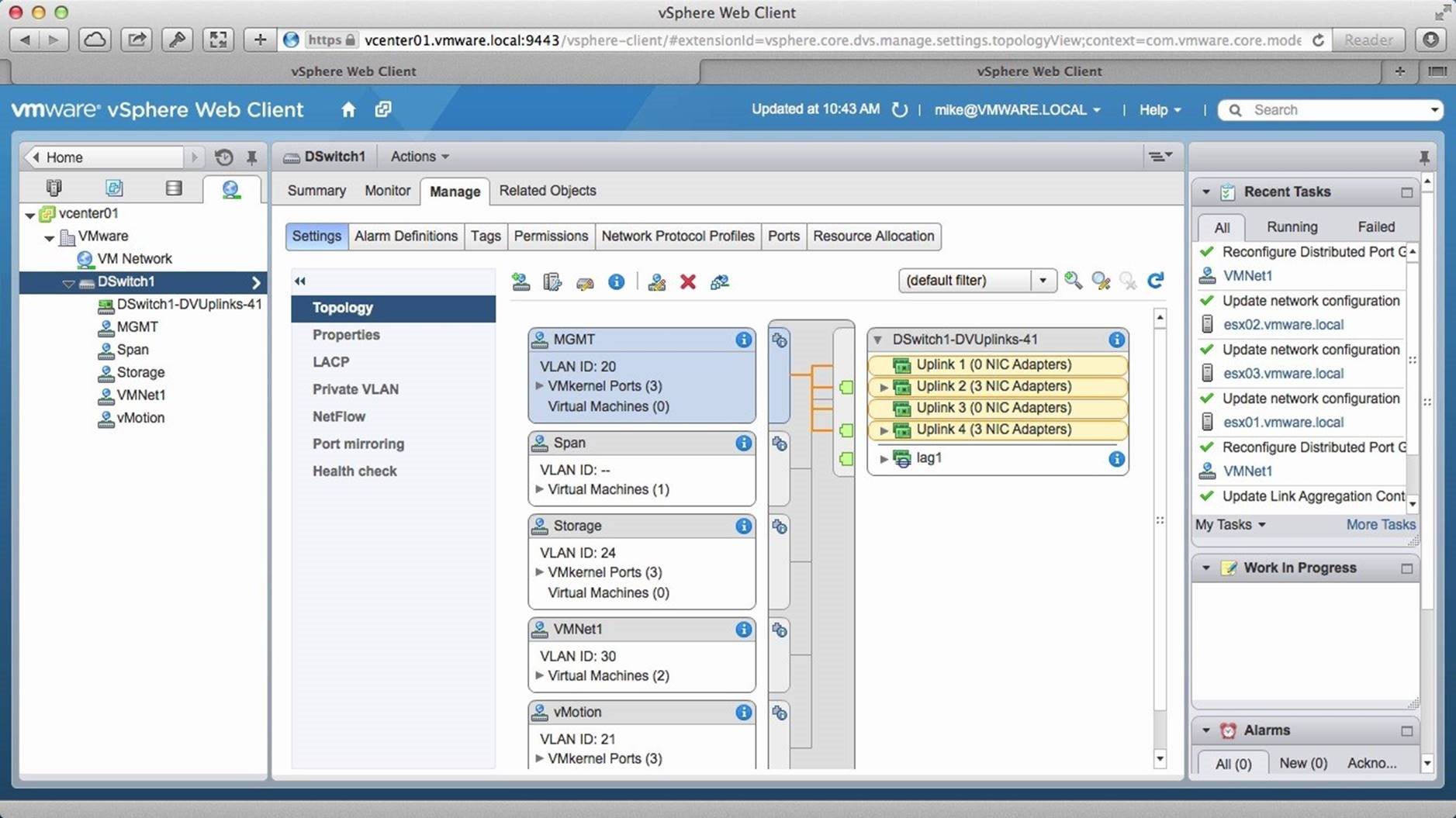
We go into [VMNet2] and see that the virtual machine web01 has been migrated to it. It is this simple to seamlessly migrate VMs from one network to another. We then go into [DSwitch1].
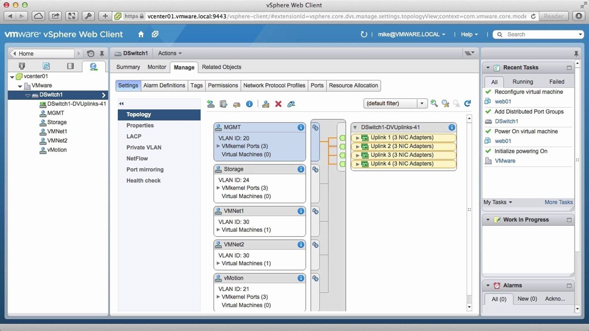
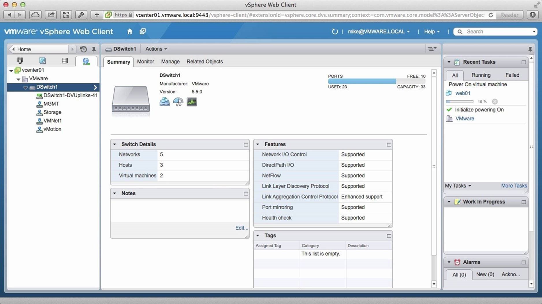
Under the Manage tab, the topology view gives us a quick overview of all the port groups available on the distributed switch, the number of VMkernel Ports, and virtual machines attached to each port group.
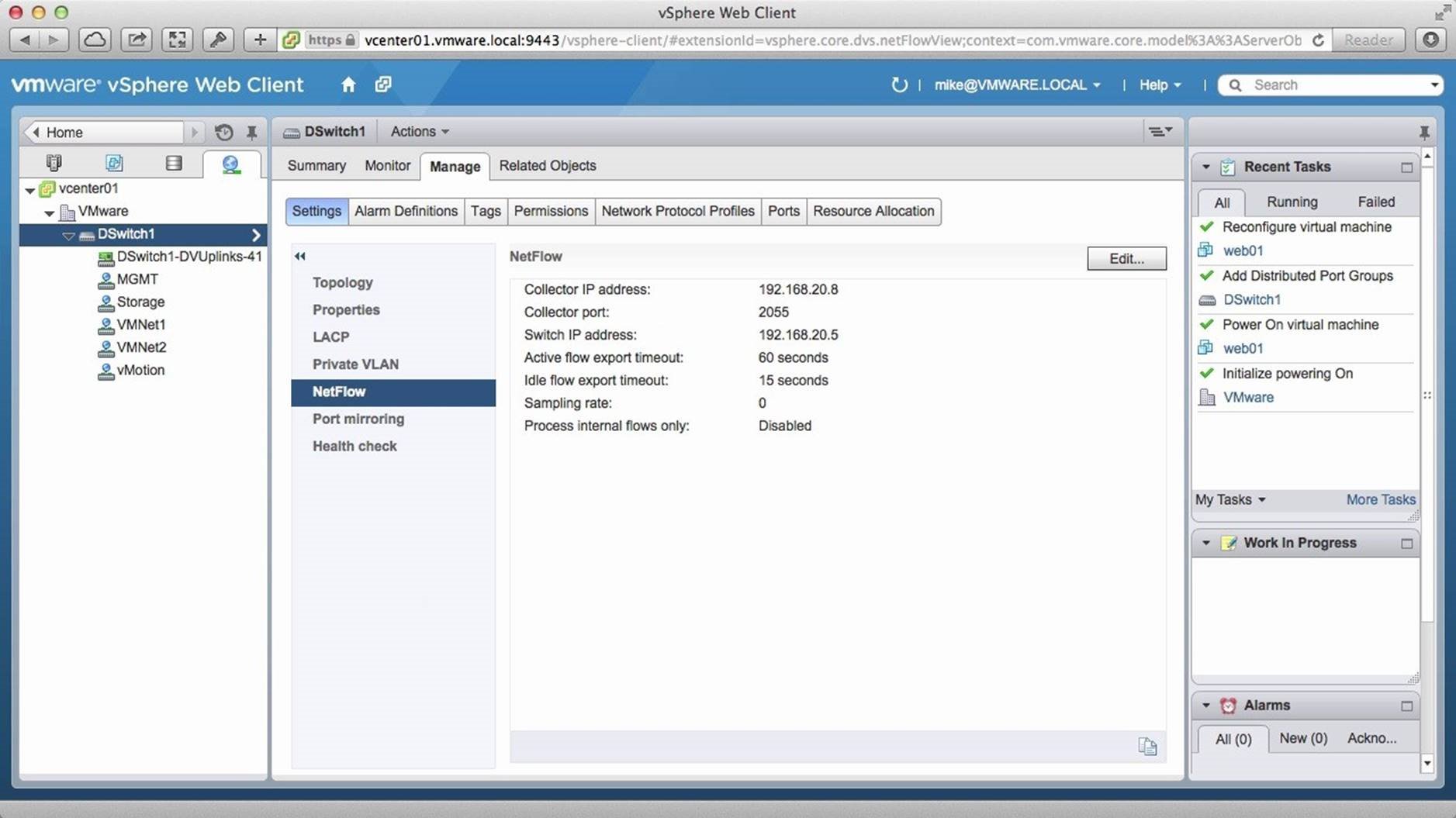
The distributed switch also provides the ability to monitor the virtual network with industry standard tools that are not available with the standard switch. For example, you can enable NetFlow.
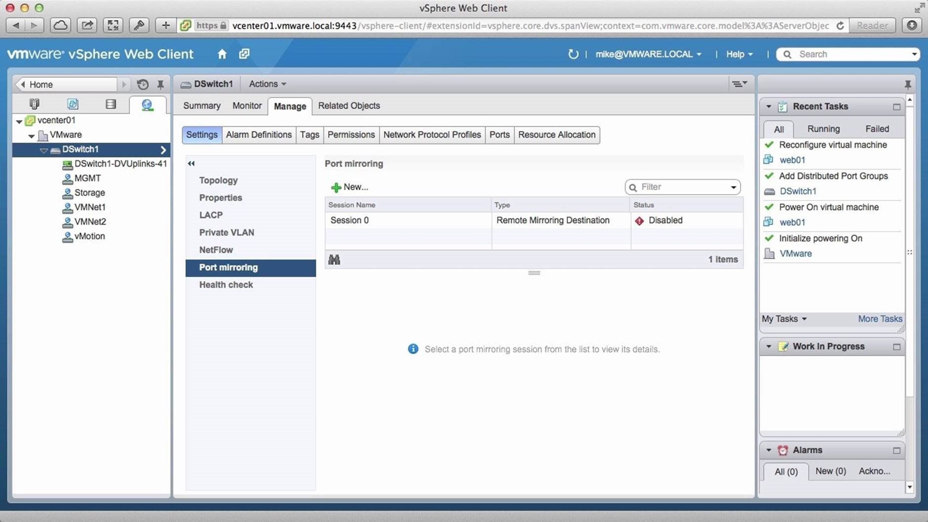
You can create mirrored ports using the Port Mirroring feature.
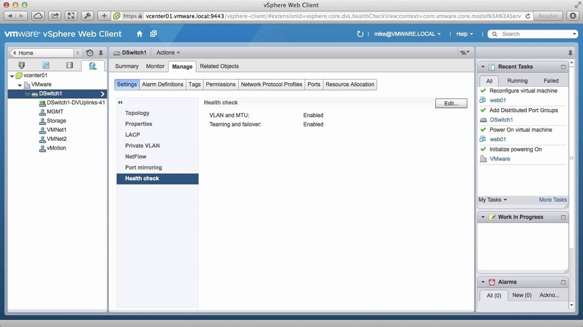
You can also enable the Health Check feature to ensure that physical and virtual networking configurations are in sync.
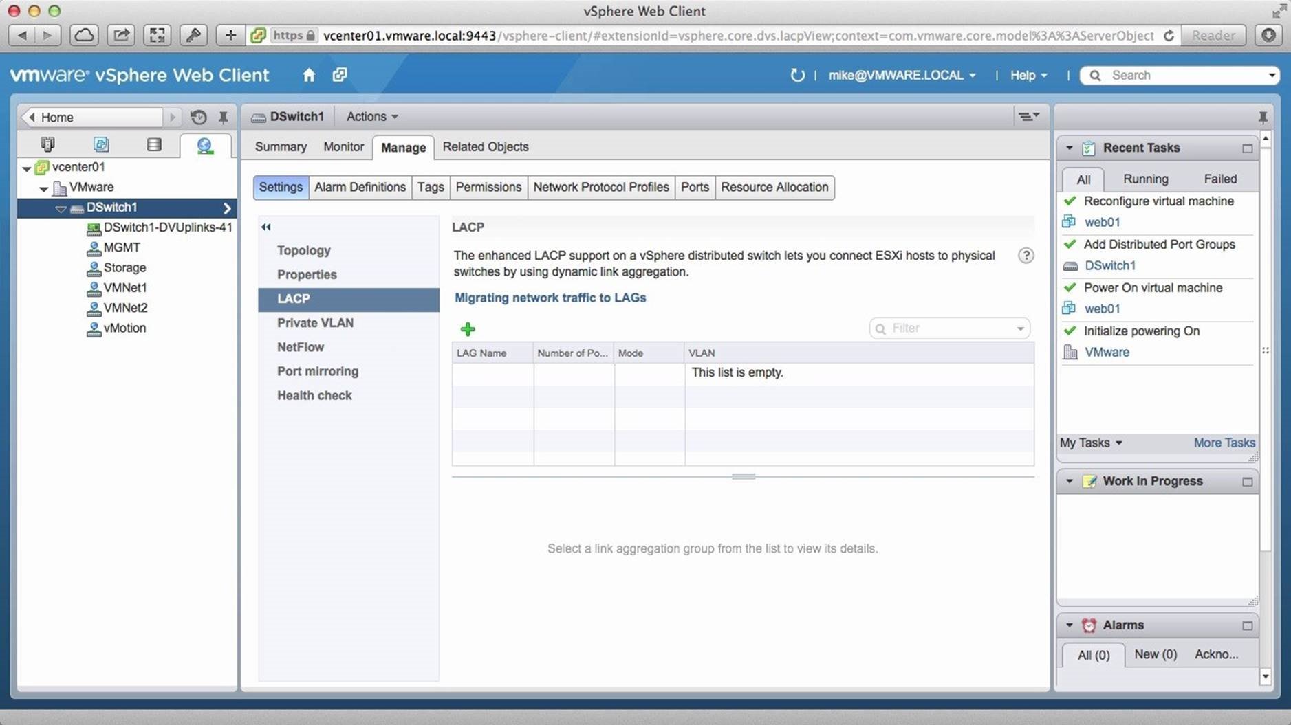
The distributed switch also includes the ability to have Link Aggregation groups using the LACP protocol.
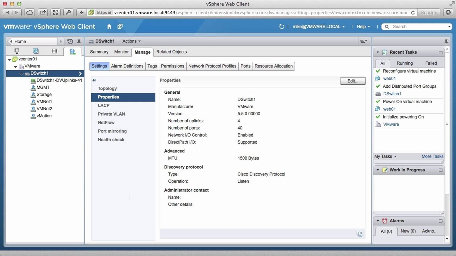
On the Properties tab, we can configure settings such as MTU, Discovery Protocol and Administrator Contact, which are features available only with the vSphere distributed switch. This concludes the introduction to VMware vSphere distributed switch walkthrough. Select the next walkthrough of your choice using the navigation pane.
Creating a vSphere Distributed Switch
This is a two-part walkthrough on how to get started with VMware Distributed Switch (VDS). Part 1 covers the steps involved in creating a vSphere Distributed Switch. Part 2 covers migrating the hosts in the VM networking traffic to the vSphere Distributed Switch. Use arrow keys to navigate through the screens.

Begin by logging onto the vSphere Web Client and go to the [Networking] section.
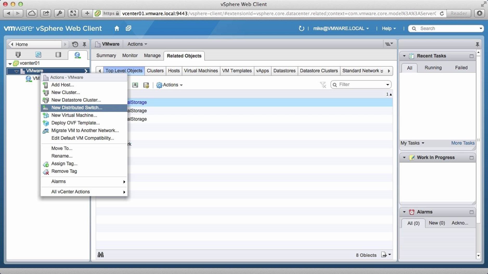
Right click on the [Datacenter] and then click on [New Distributed Switch].
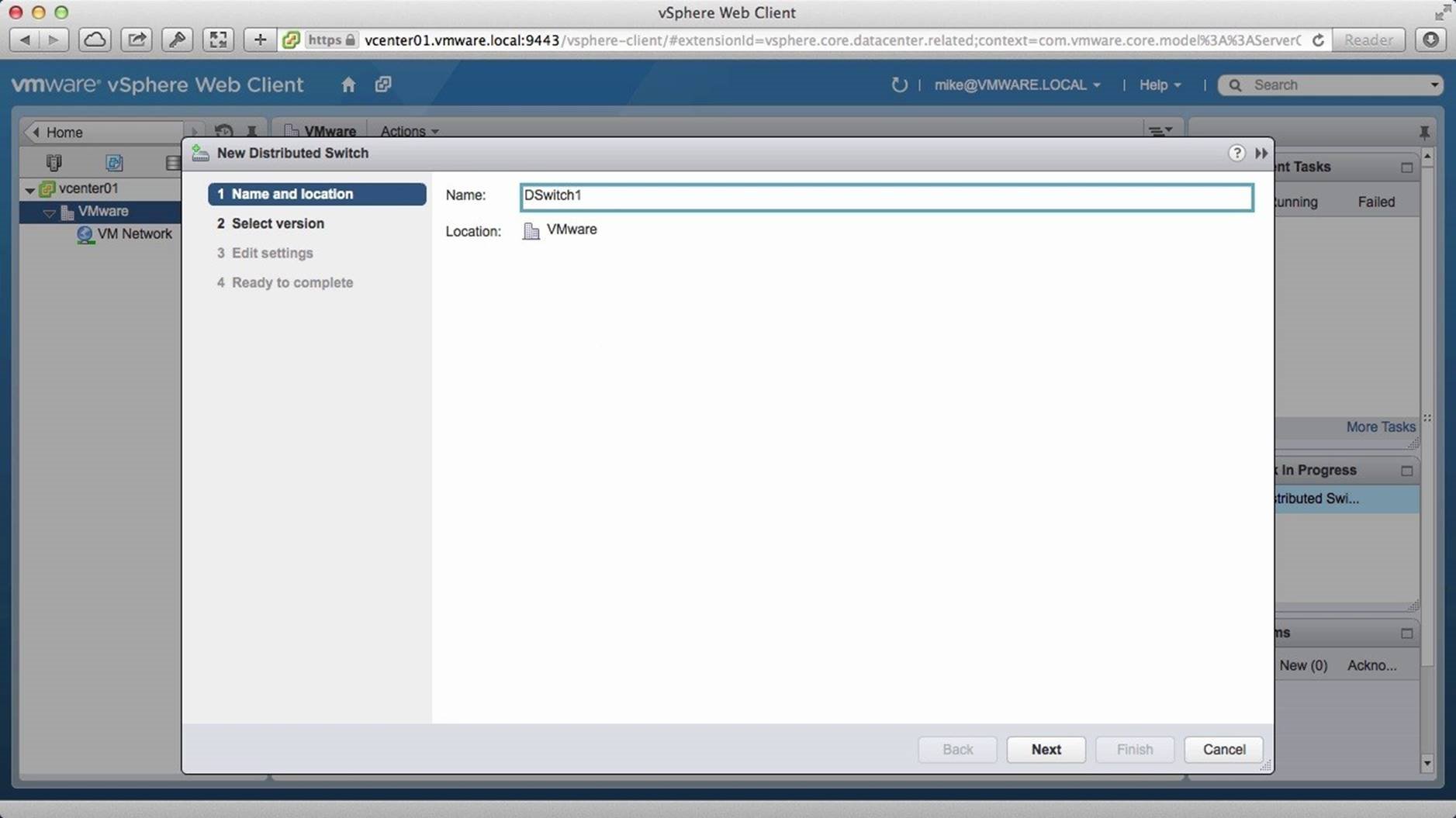
Assign a name and click on [Next].
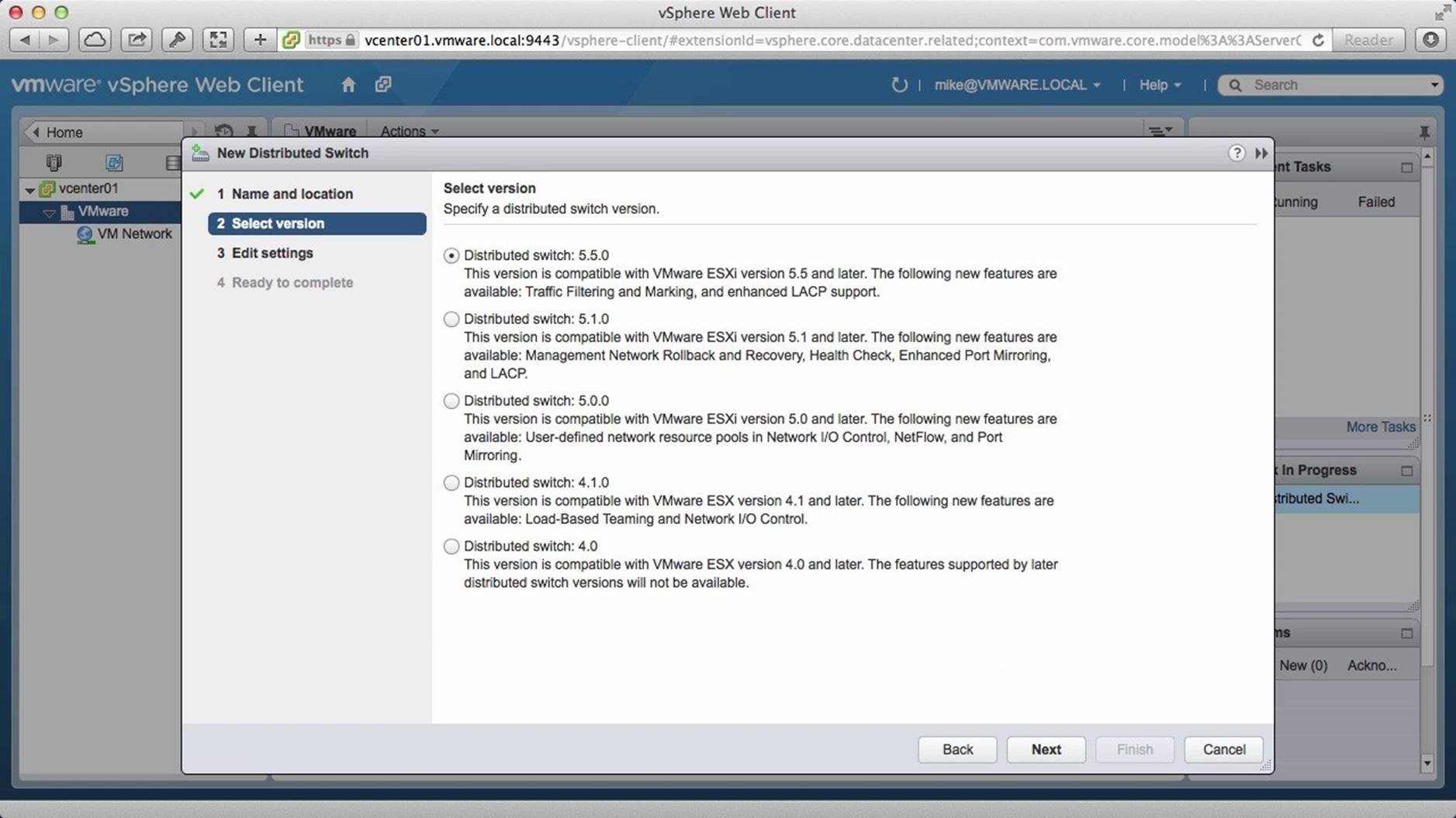
Choose the version of the distributed switch you wish to deploy. We will configure the latest 5.5.0 version. Click on [Next].
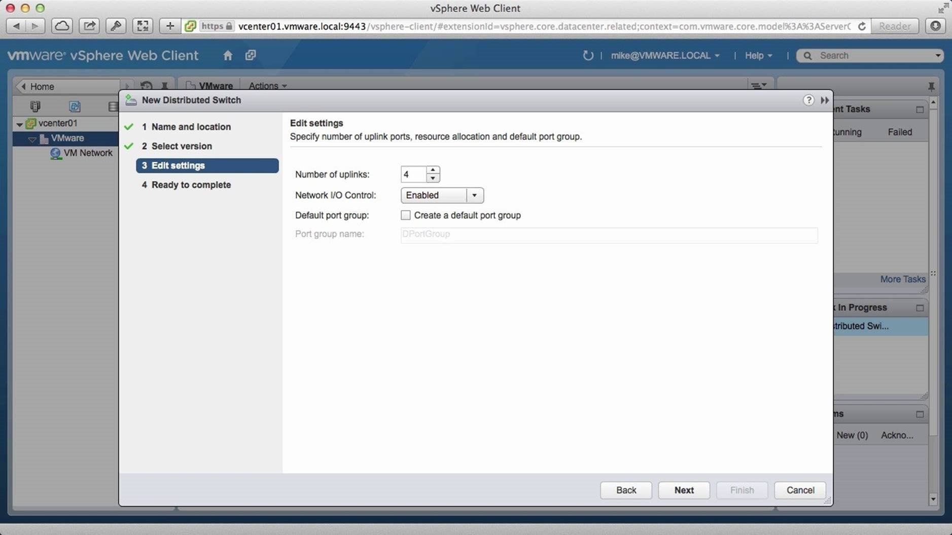
Define the number of uplinks. We set it to be 4. Enable [Network I/O Control] and uncheck [Create a Default Port Group]. Then click on [Next].
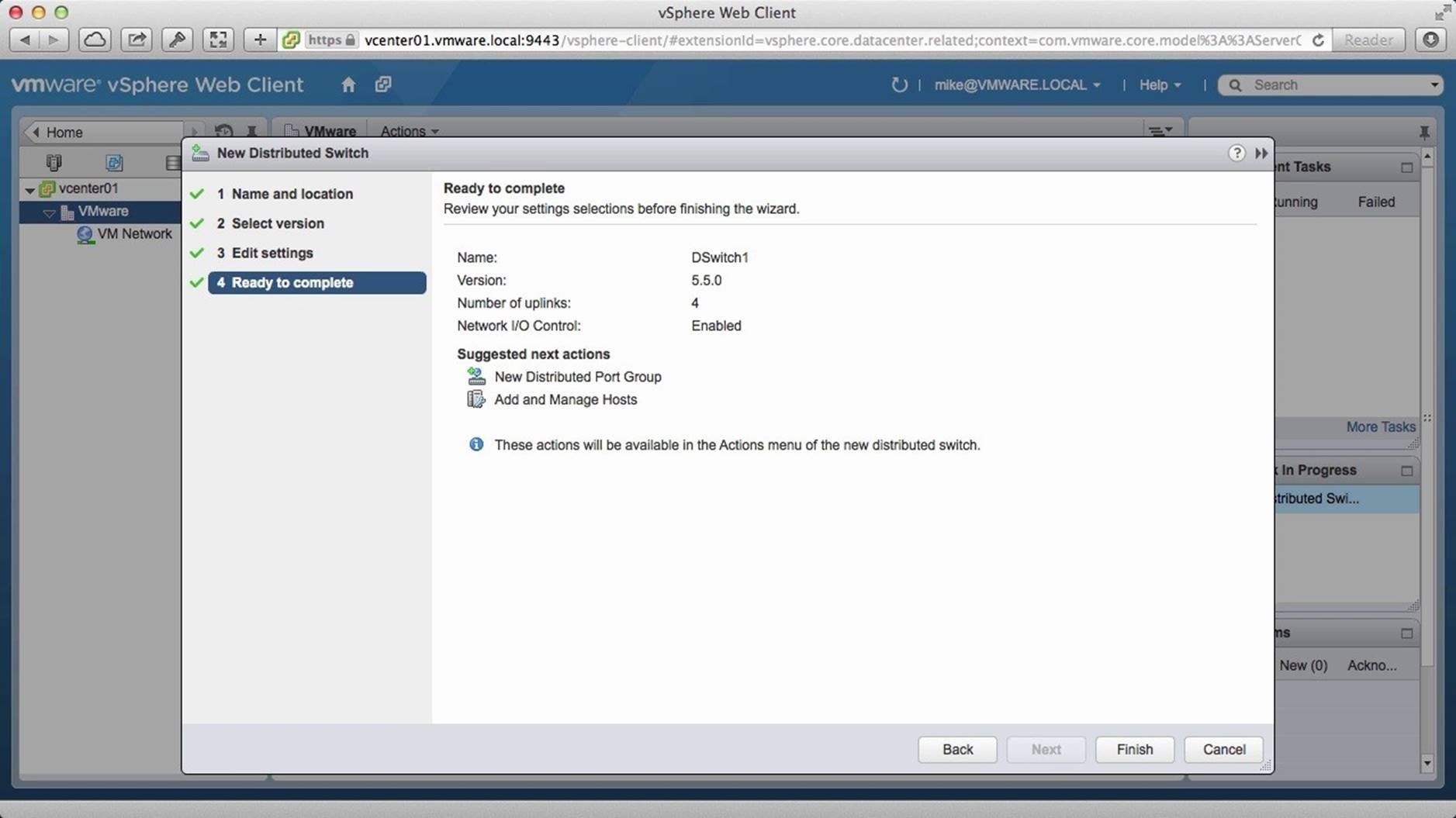
Review the settings and click on [Finish].
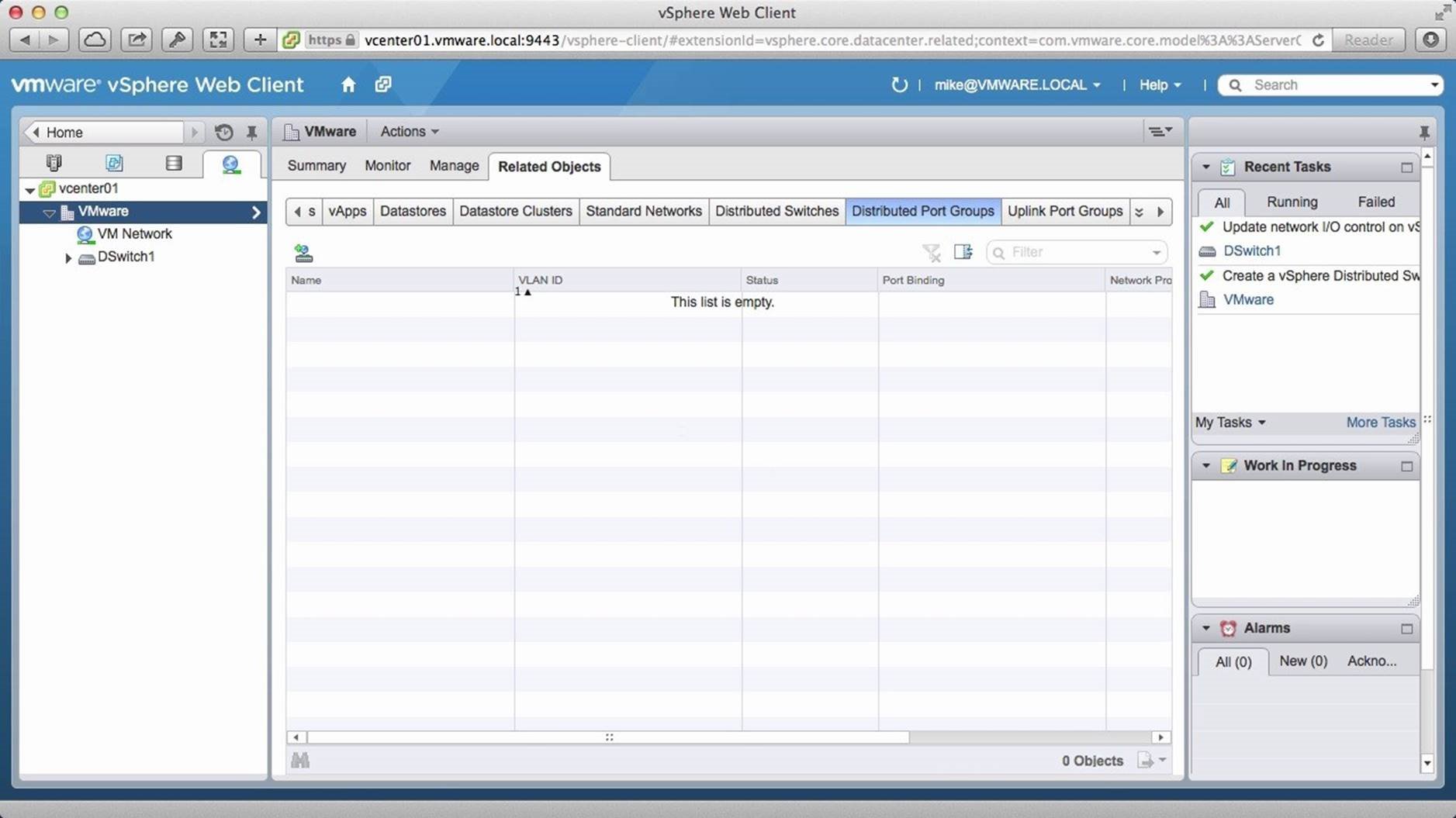
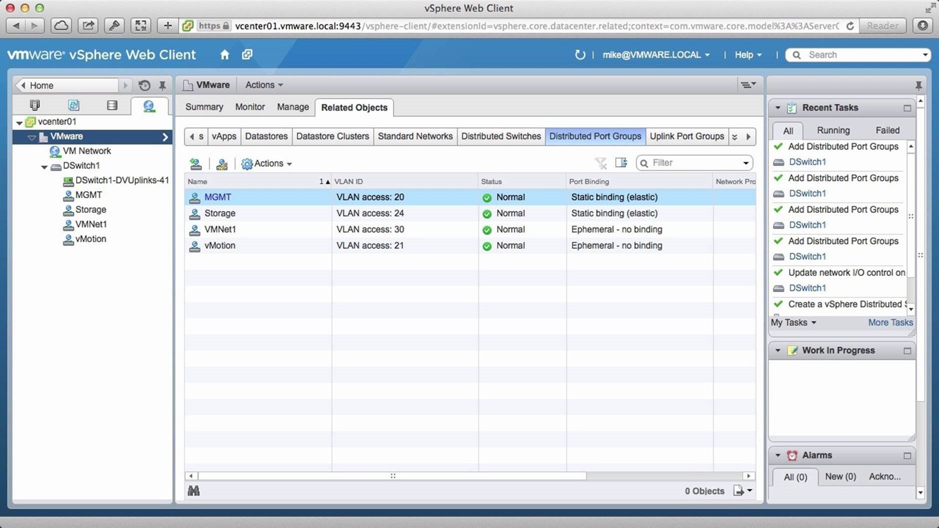
Going into the [Distributed Port Groups] tab, we see that we do not have any distributed port groups. Next, go to the [Uplink Port Groups] tab.
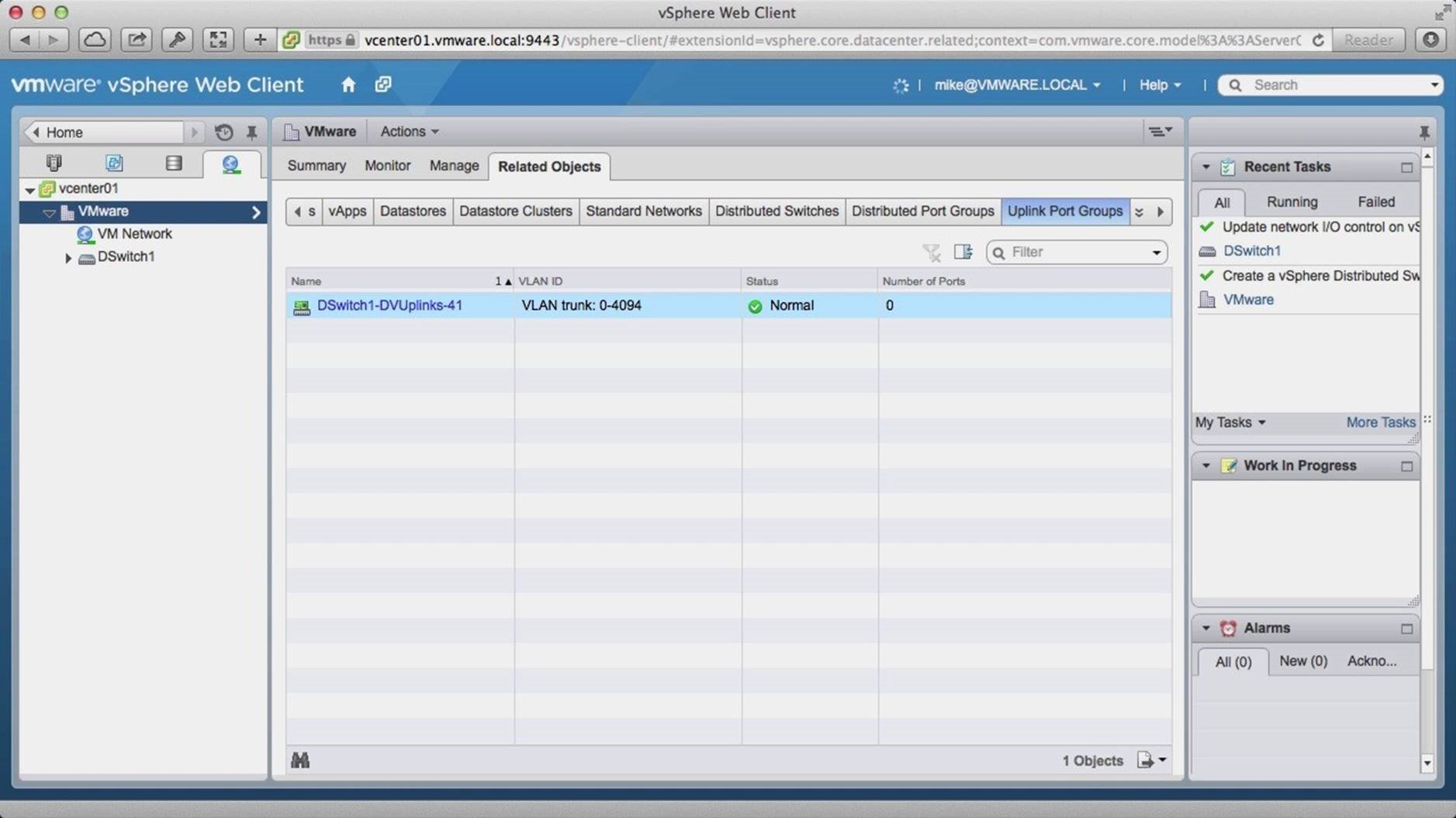
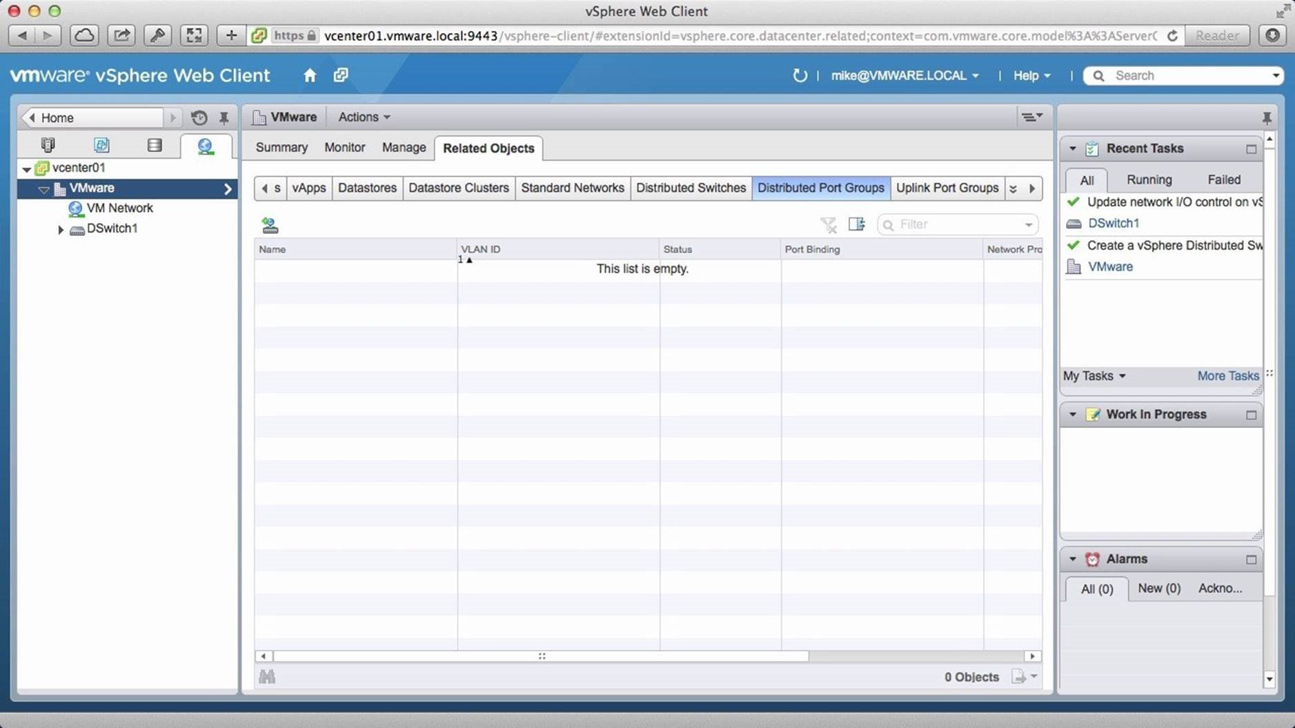
We see that we have one uplink configuration that was set when the distributed switch was created. Now we need to create a new distributed port group. To do this, go back to the [Distributed Port Group] tab.
Click on the new port group [Icon].
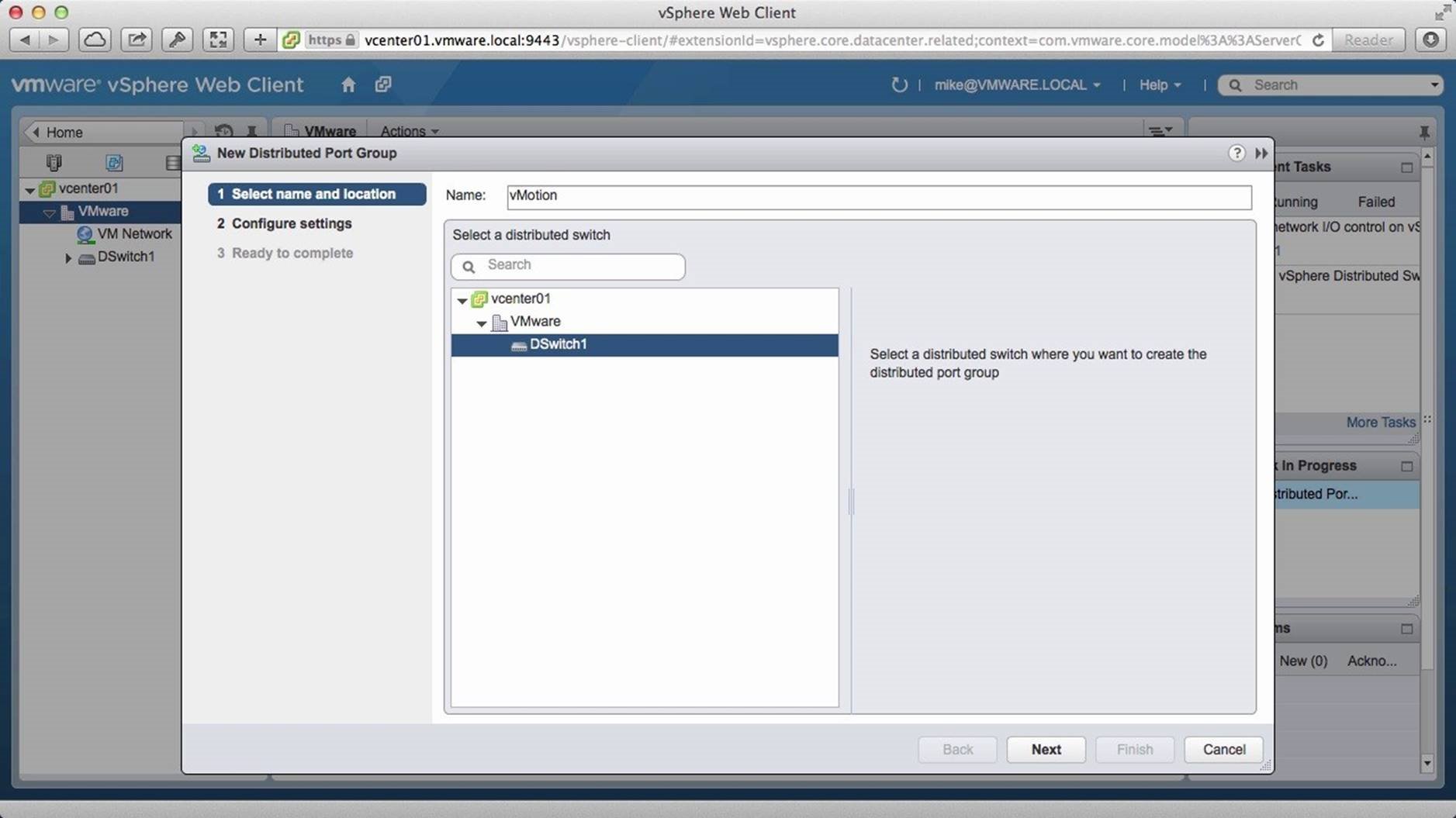
Assign a name to the new distributed port group; we name it “vMotion”. Select the [Distributed Switch] and click on [Next].
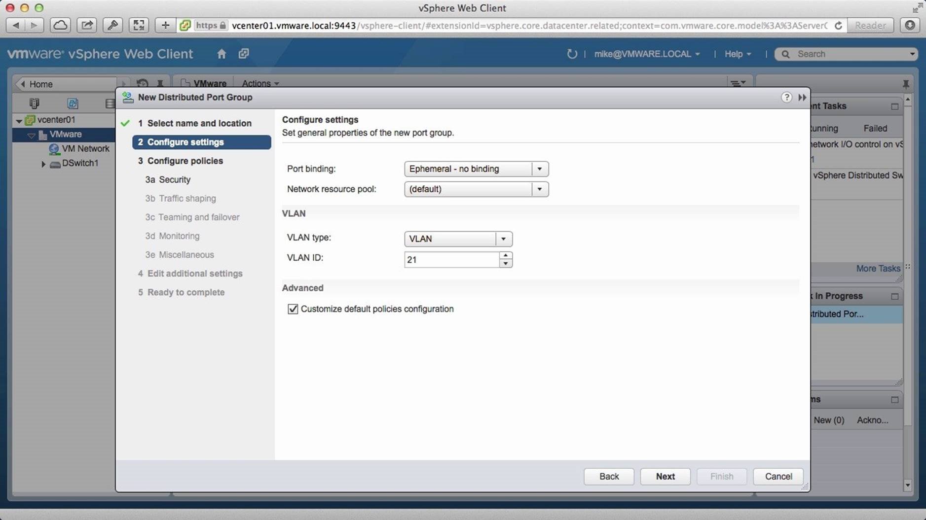
Change the port binding to “Ephemeral - no binding”. Choose the VLAN type as “VLAN” and specify the ID. Check the box against “Customize default policies configuration”. This will allow you to specify additional details. Then click on [Next].
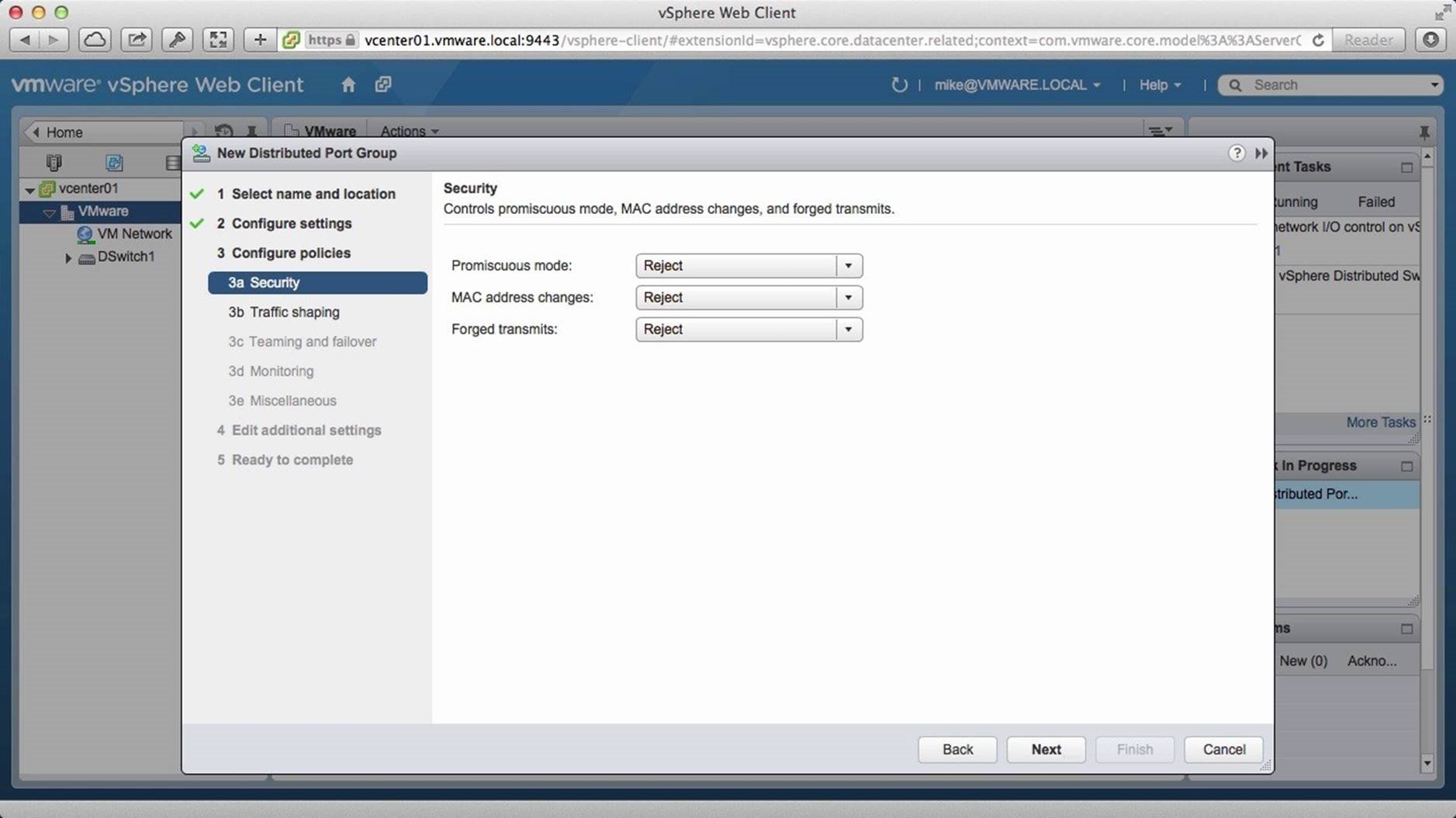
Retain the default configuration for security and click on [Next].
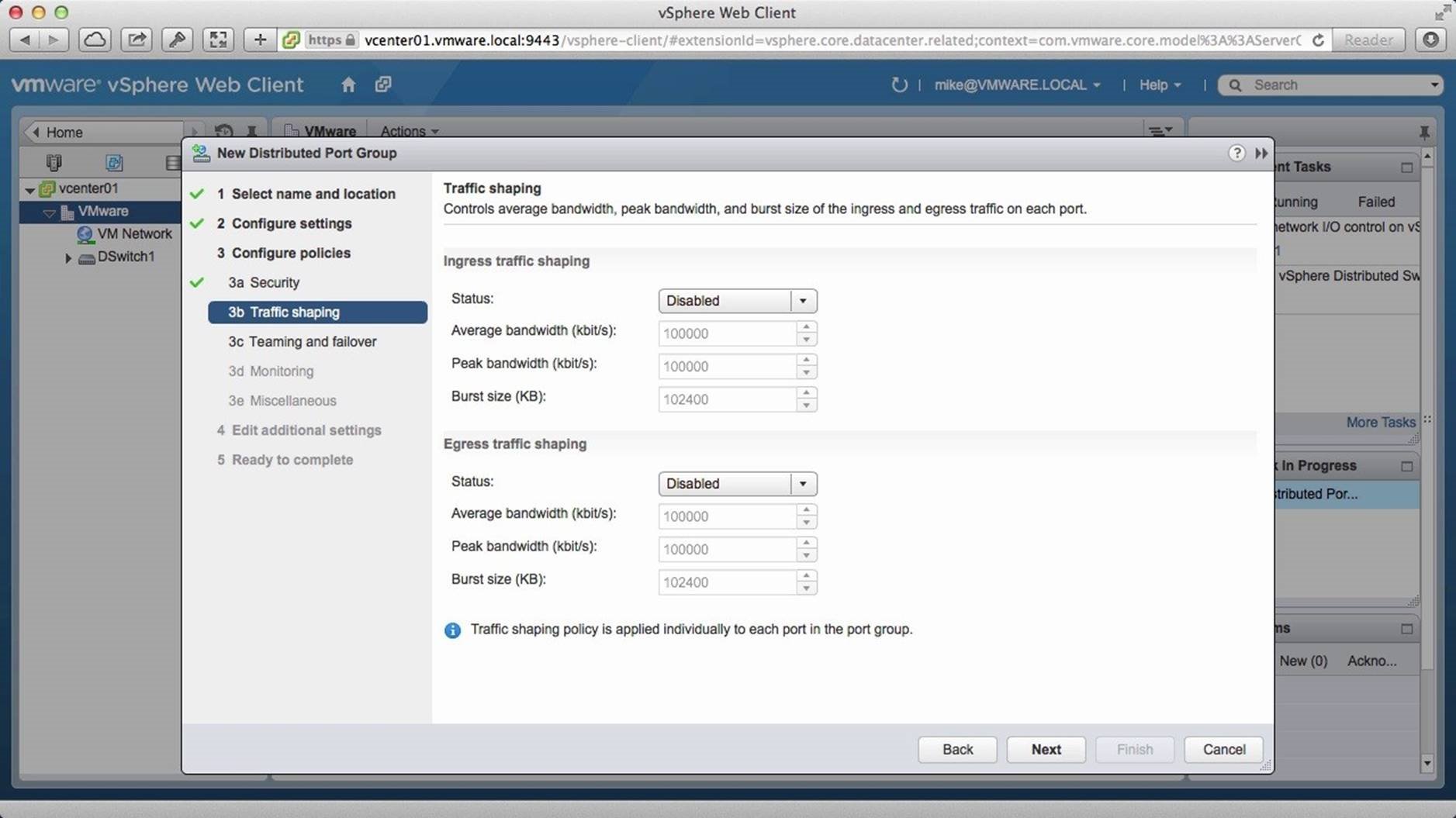
Retain the defaults for “Traffic shaping” and click on [Next].
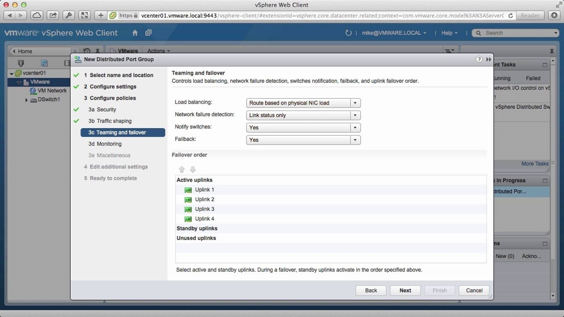
Change load balancing to “Route based on physical NIC load” and click on [Next].
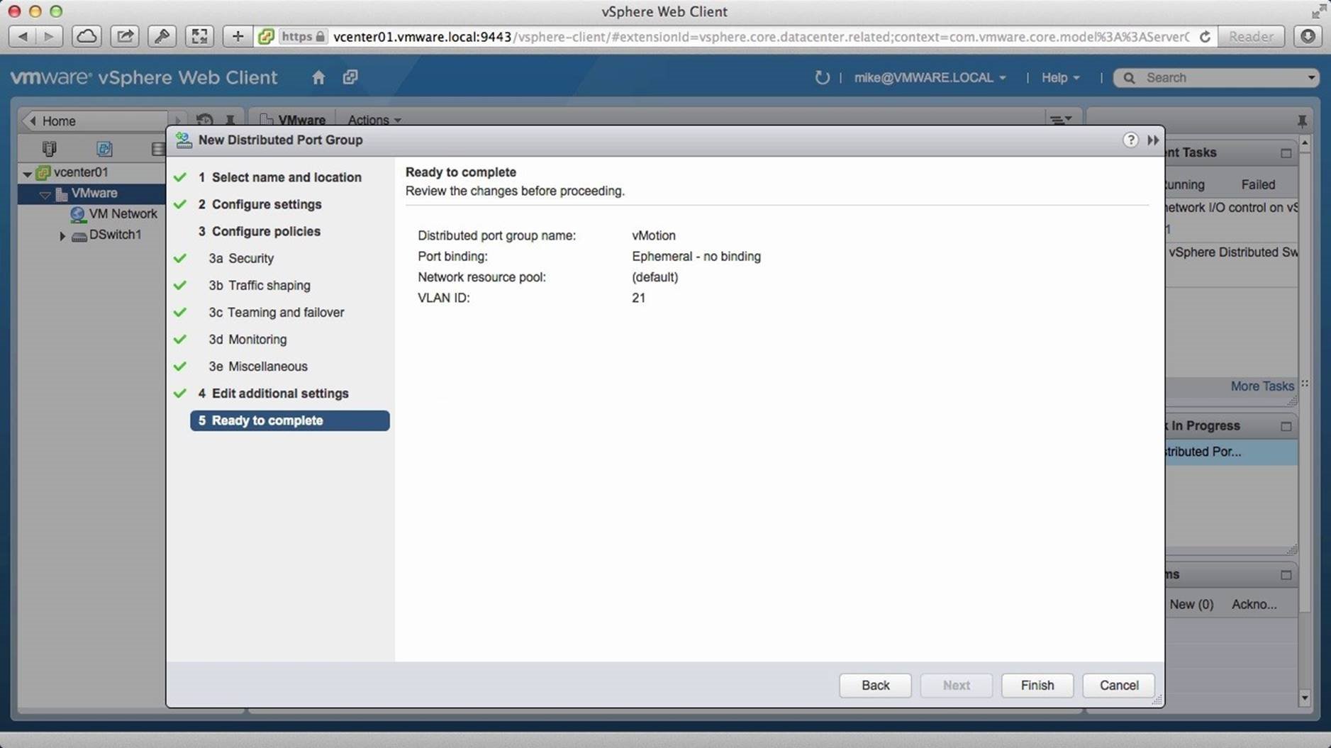
Retain the defaults for the remaining settings and click on [Finish].
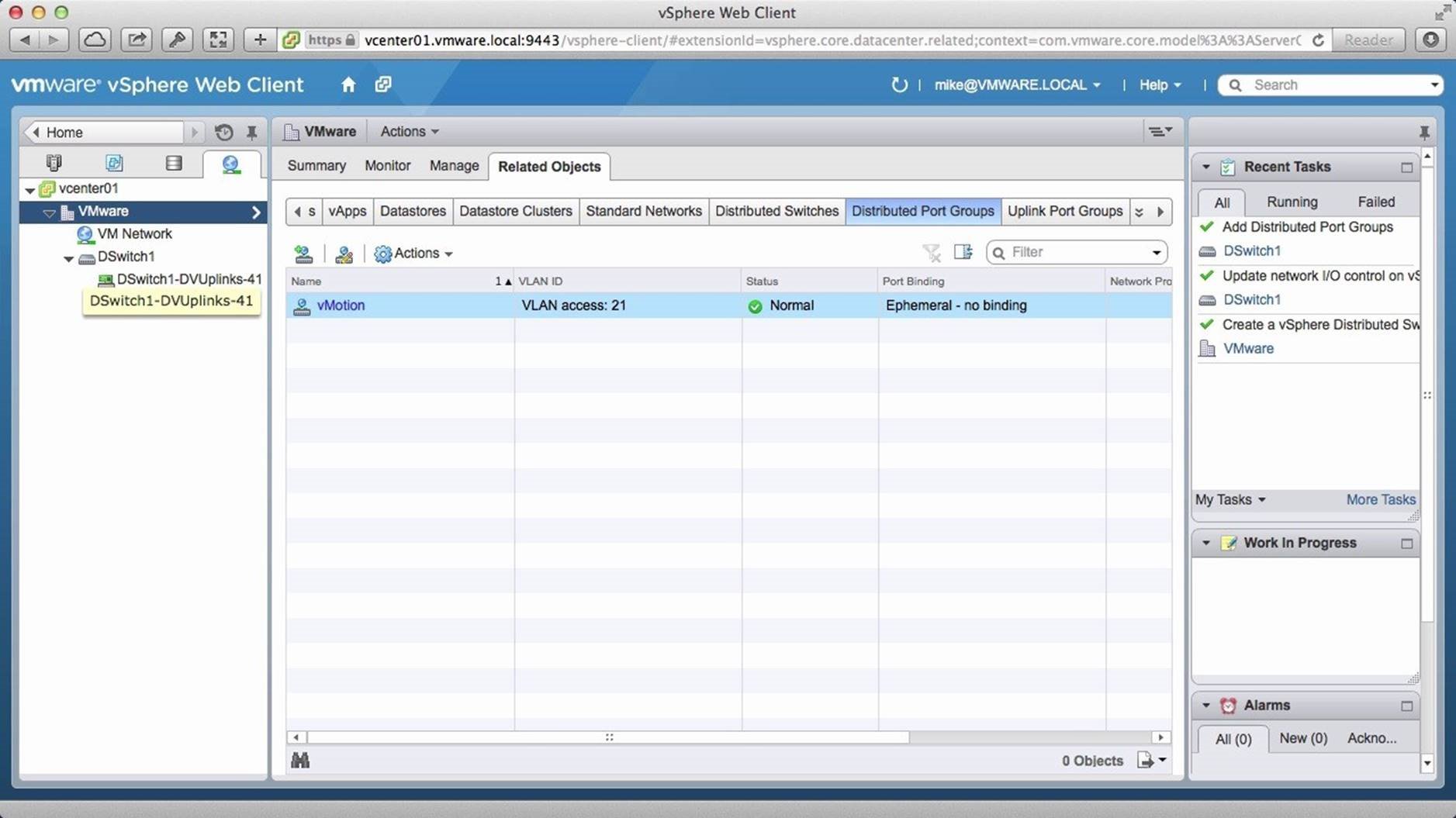
The vMotion port group has been created. Next we need to create the management port group.
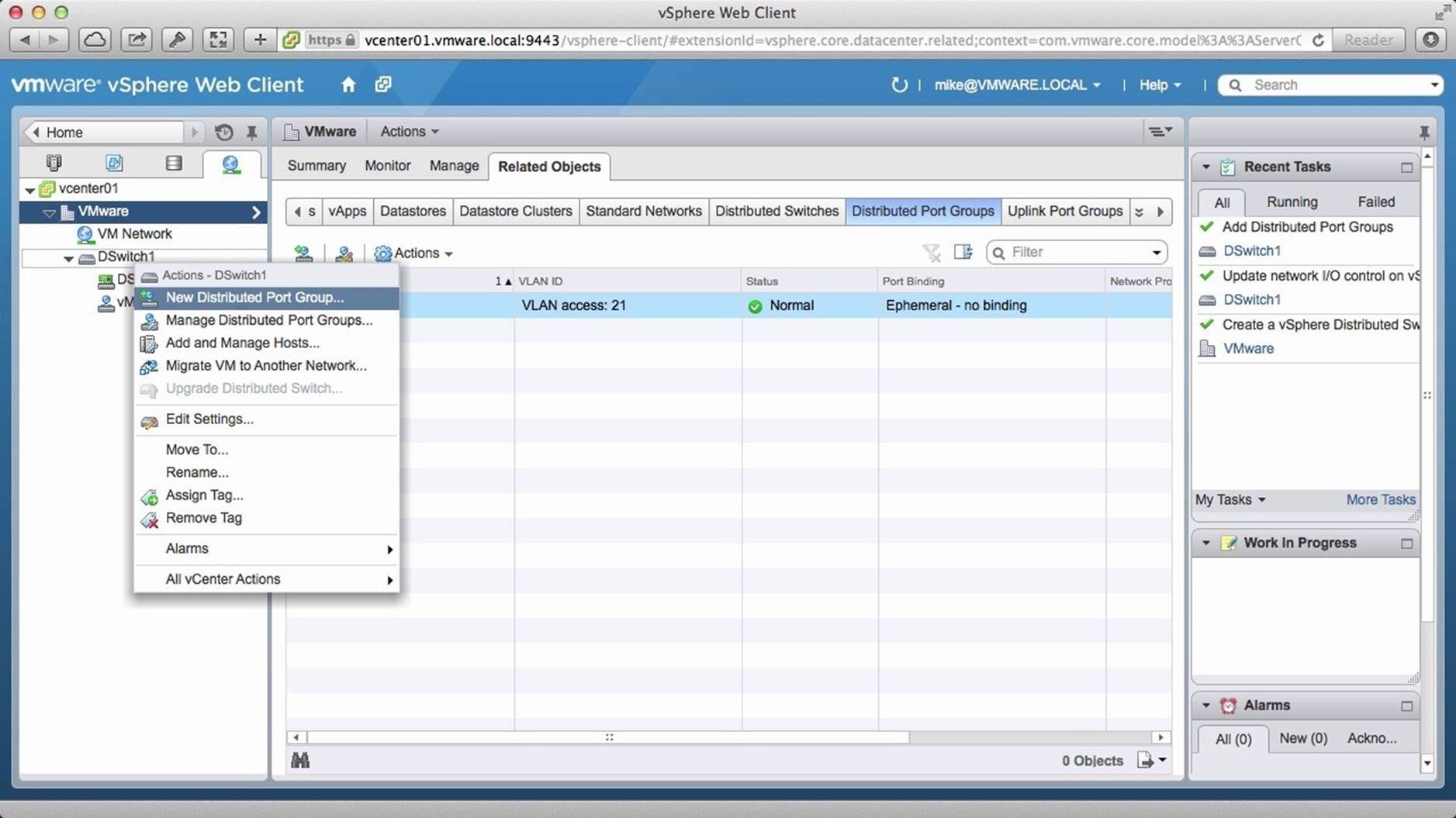
Right click on the [Distributed Switch] and click on [New Distributed Port Group].
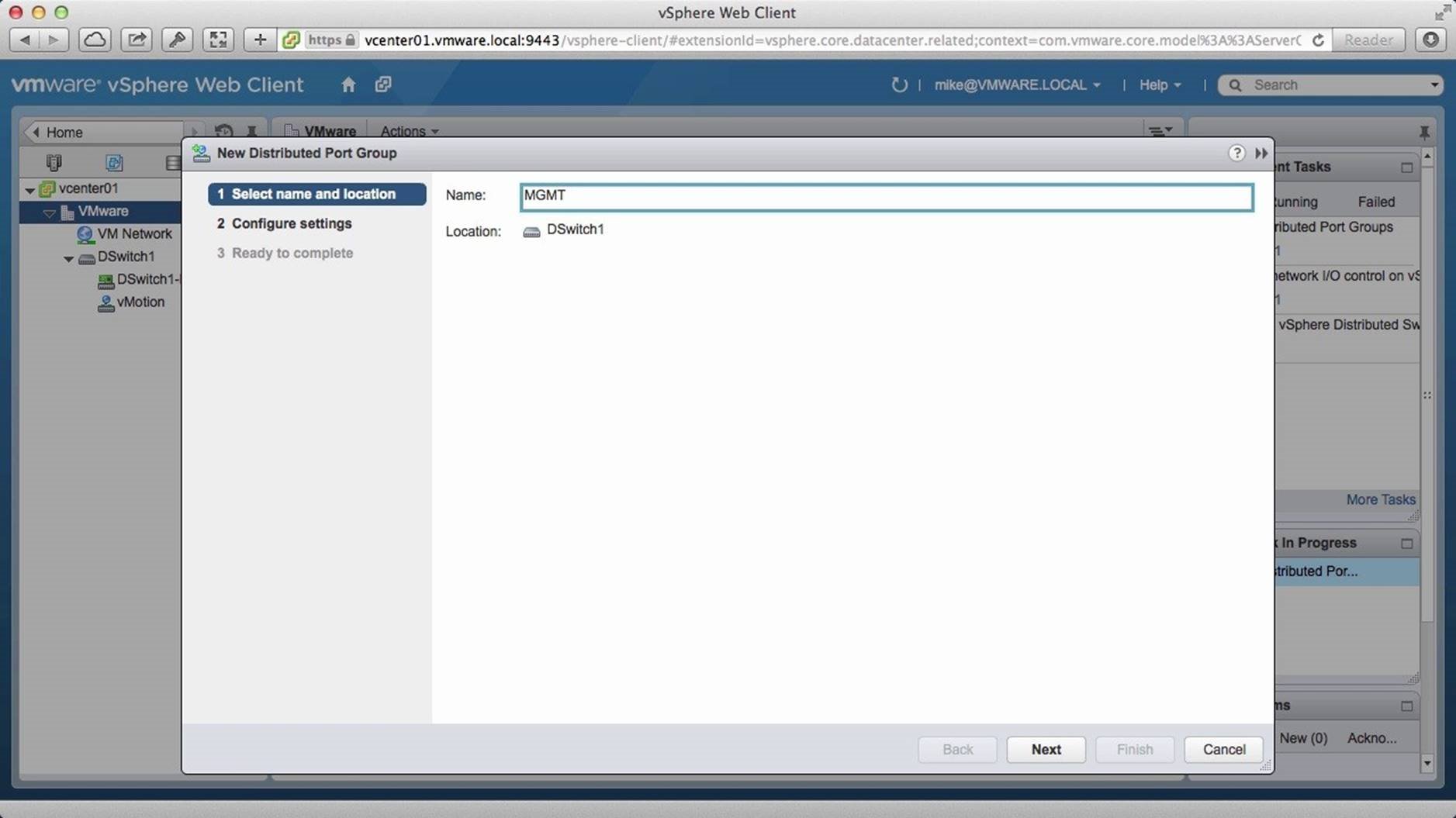
Assign a name and click on [Next].
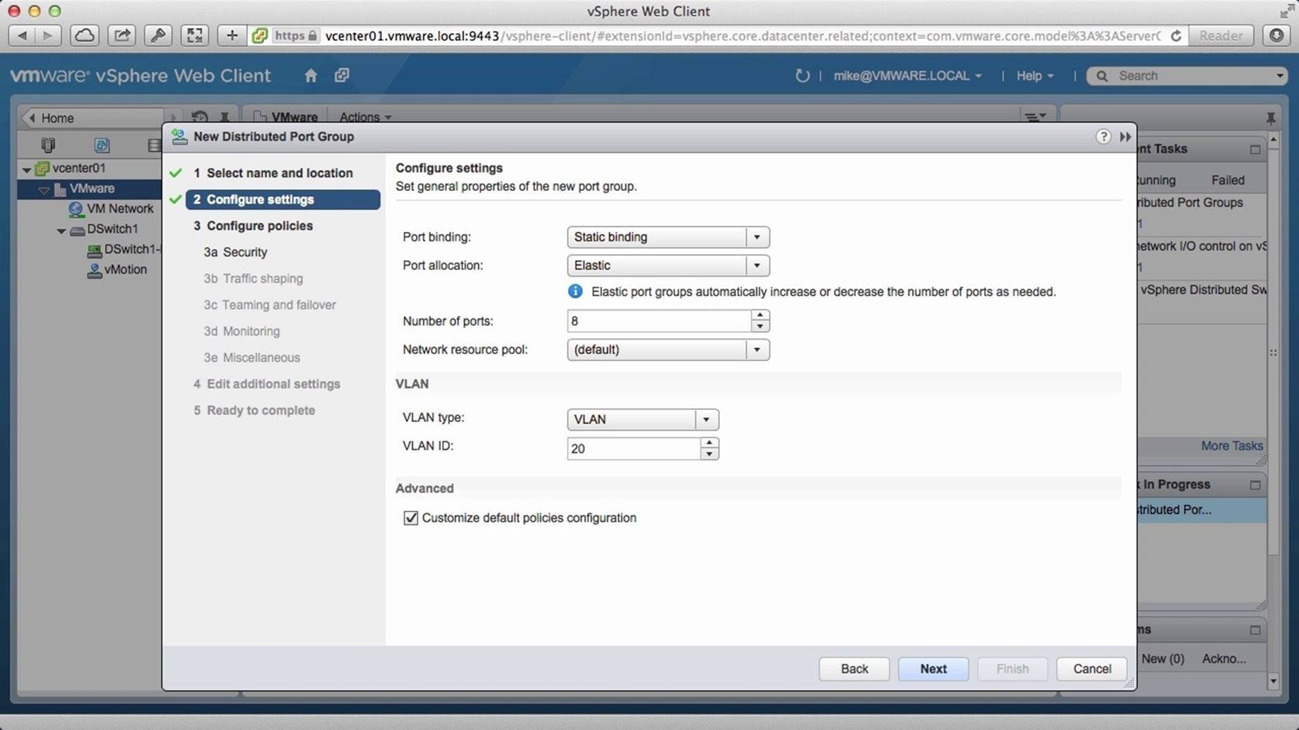
Select “Static binding” for port binding, select “VLAN” as the VLAN type and specify the ID. Check the box to “Customize default policies configuration” and click on [Next].
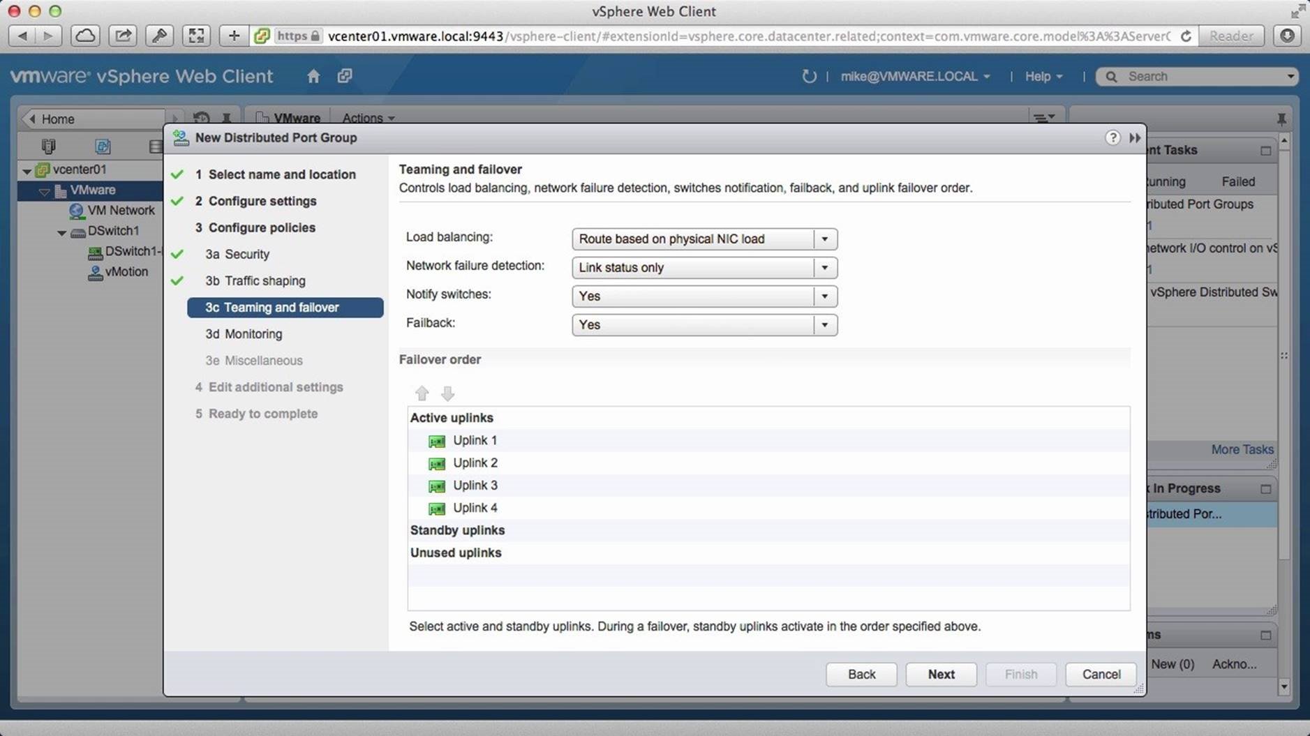
Retain the defaults for Security and Traffic Shaping. Then select “Route based on physical NIC load” for load balancing and click on [Next].
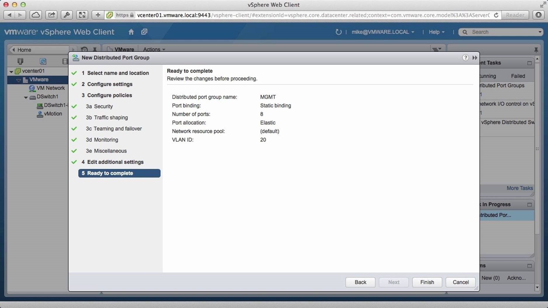
Retain the default selections for the remaining configurations and click on [Finish]. Following the steps involved in creating the management port group, create the storage and VMNet port groups.
We have now created a distributed switch and all the port groups required. This concludes Part 1 of the two-part walkthrough on how to get started with the vSphere Distributed Switch. Continue with Part 2, which shows how to migrate host and VM network traffic to the VDS.
Migrating Host and VM Networking Traffic to VDS
This is Part 2 of the two-part walkthrough on how to get started with vSphere Distributed Switch (VDS). Part 1 covered the steps involved in creating a distributed switch and the port groups. Part 2 covers migrating the host and VM network traffic to the vSphere Distributed Switch. Use arrow keys to navigate through the screens.
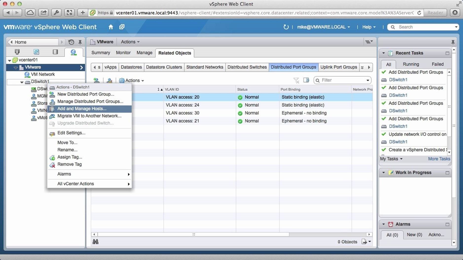
After creating the distributed switch, right click on the [Distributed Switch] and click on [Add and Manage Hosts].
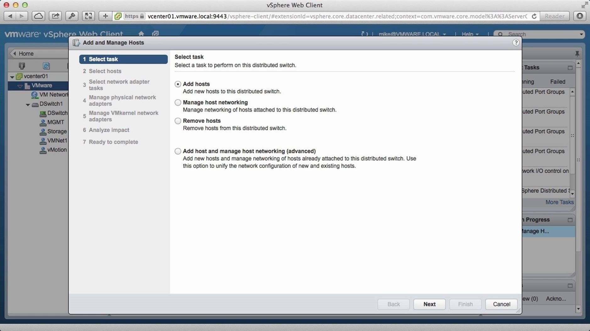
Select [Add Hosts] and click on [Next].
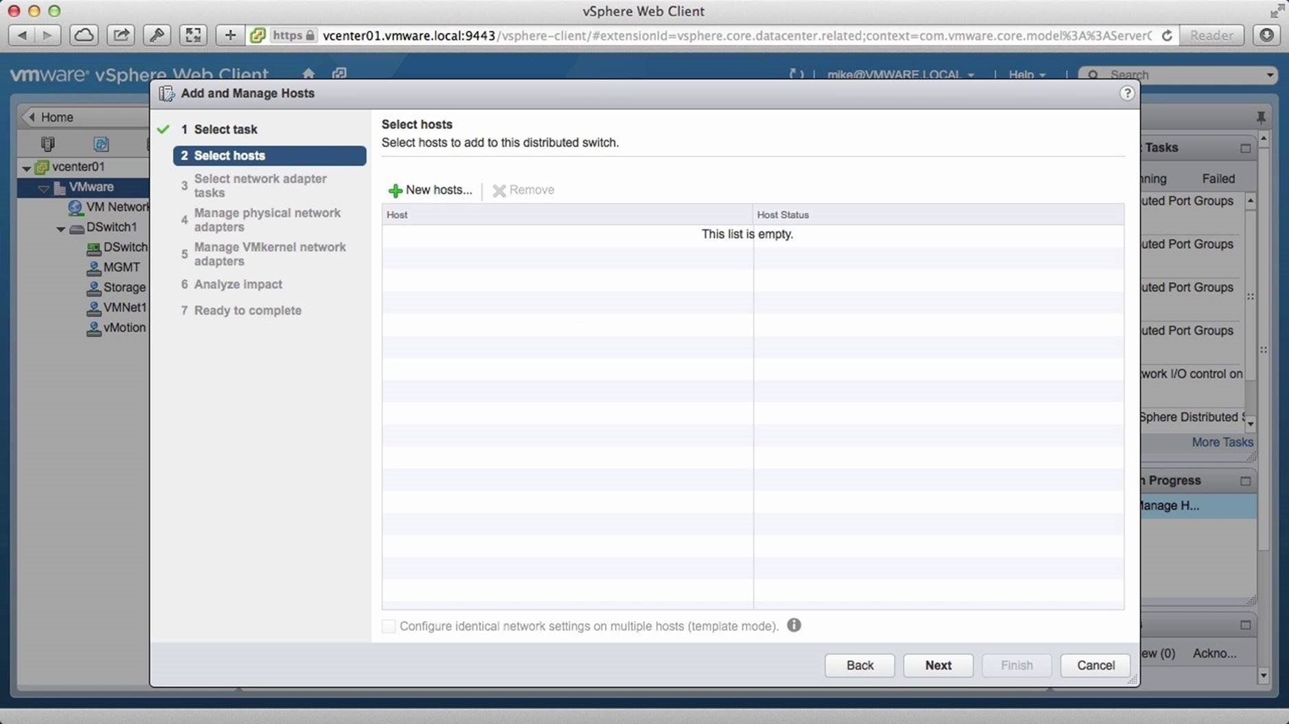
Click on the add [+New Hosts] button.
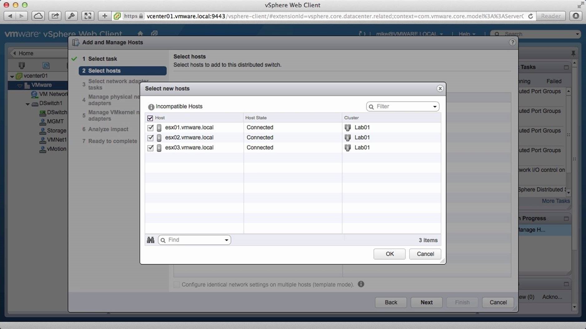
Select the hosts that you wish to move to the distributed switch and click on [OK] and click on [Next].
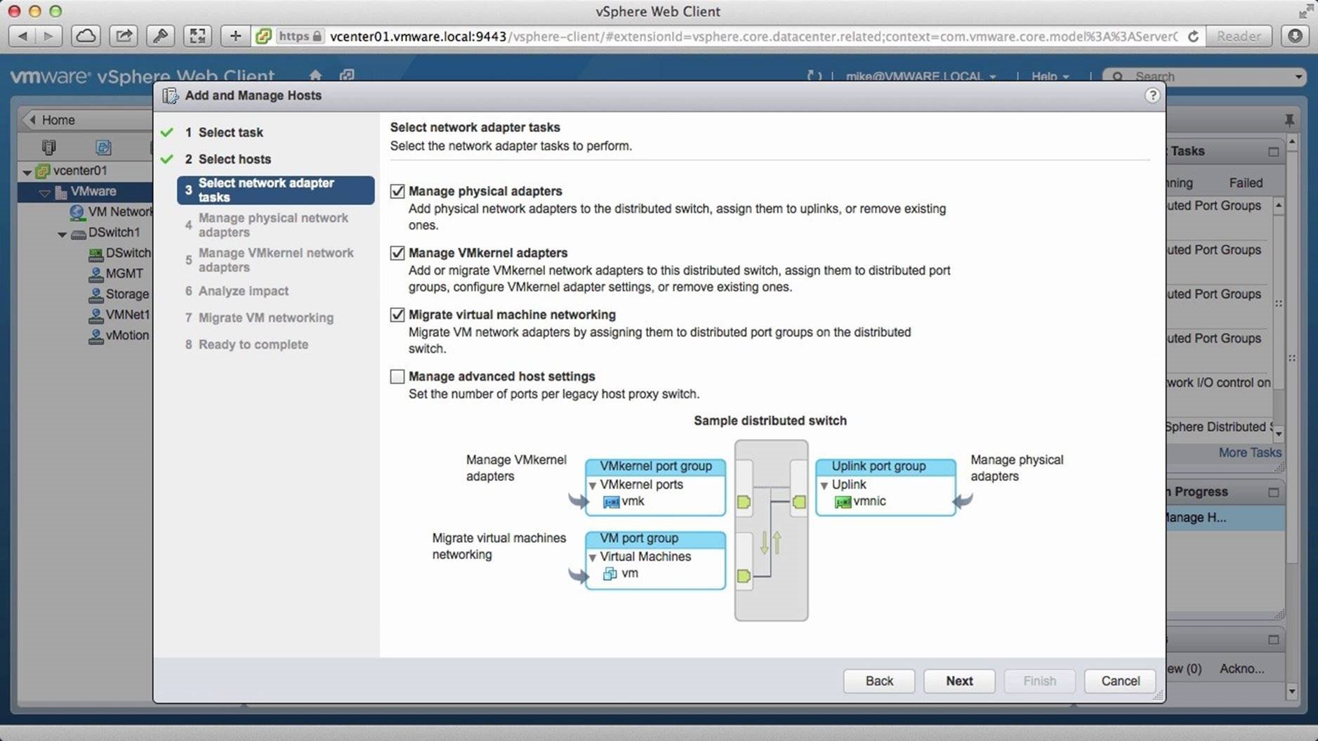
Select [Migrate Virtual Machine Networking] and click on [Next].
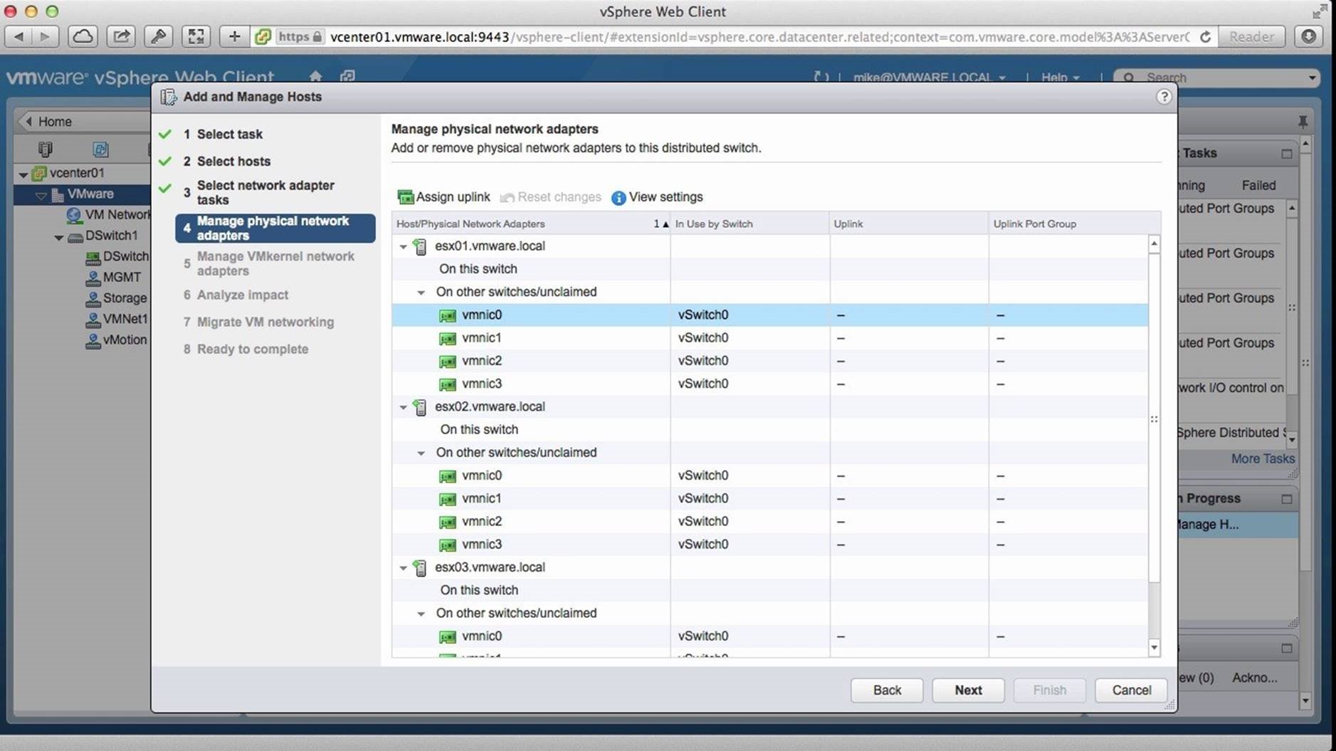
Here we have the list of all the VM NICs on the hosts that will be migrated. We need to move all of these NICs to the distributed switch. To do this, select the [NIC] and click on [Assign Uplink].
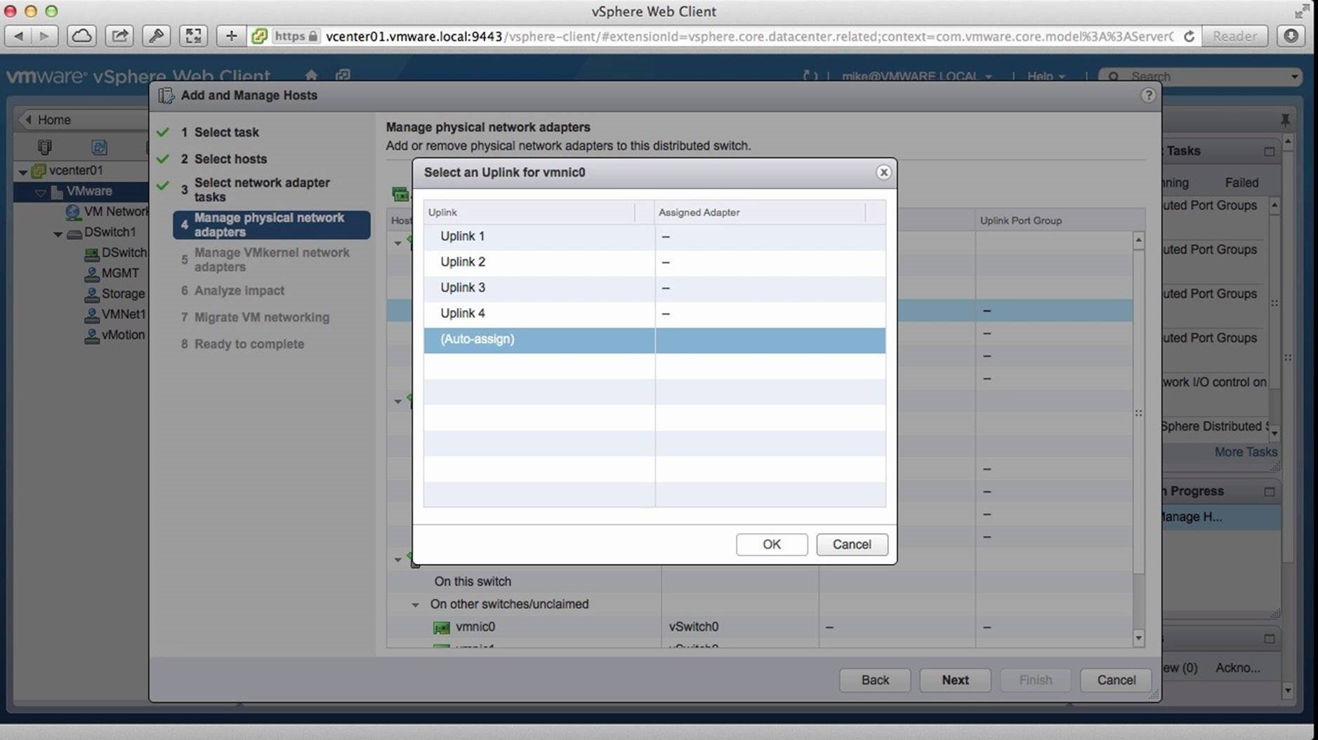
Repeat this for all NICs on each hosts and click on [Next].
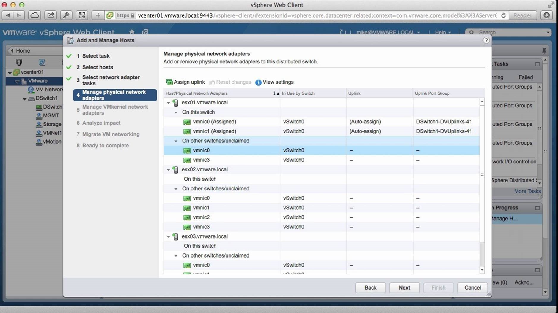
Repeat this for all the NICs associated with the hosts and click on [Next].
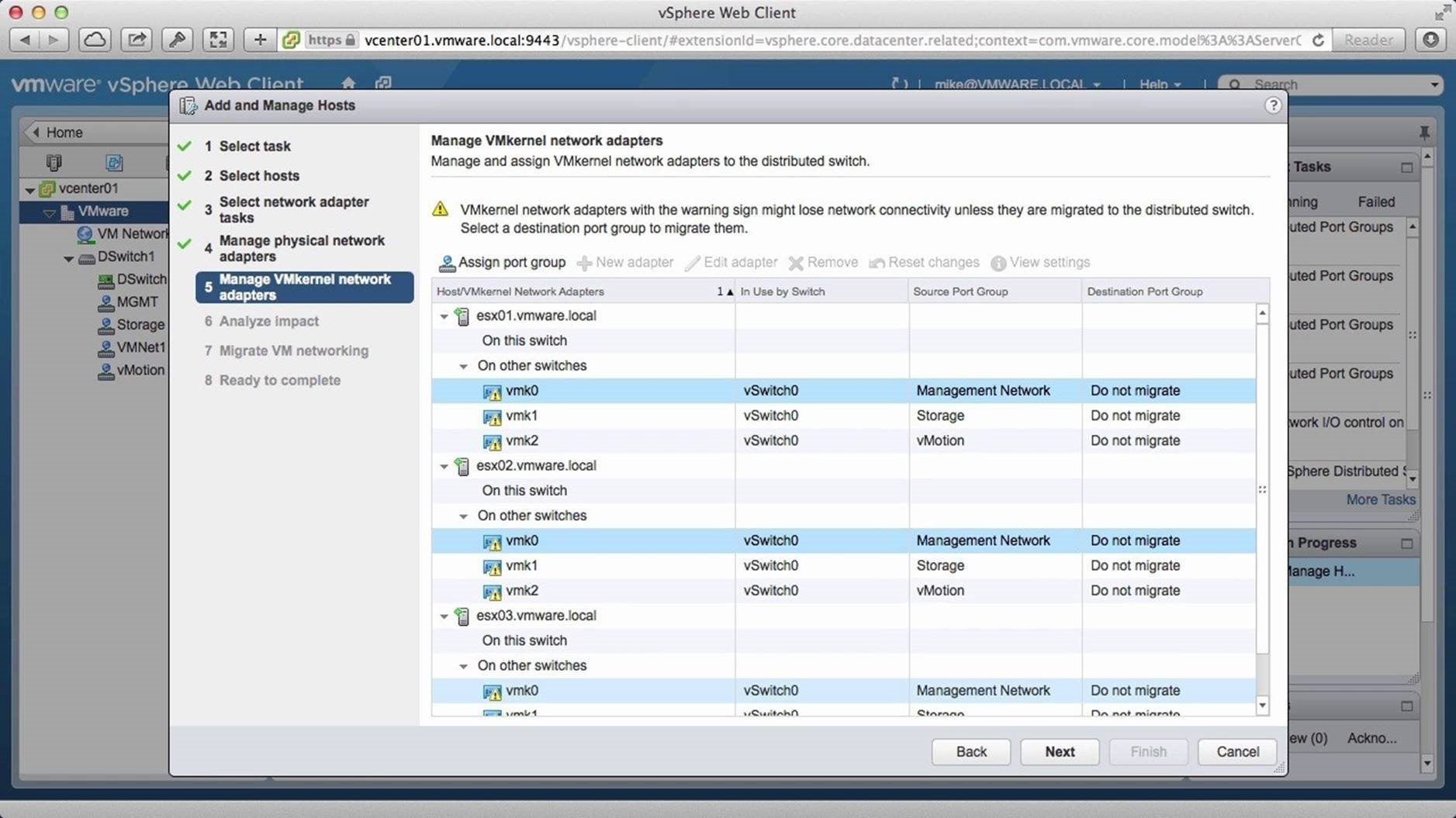
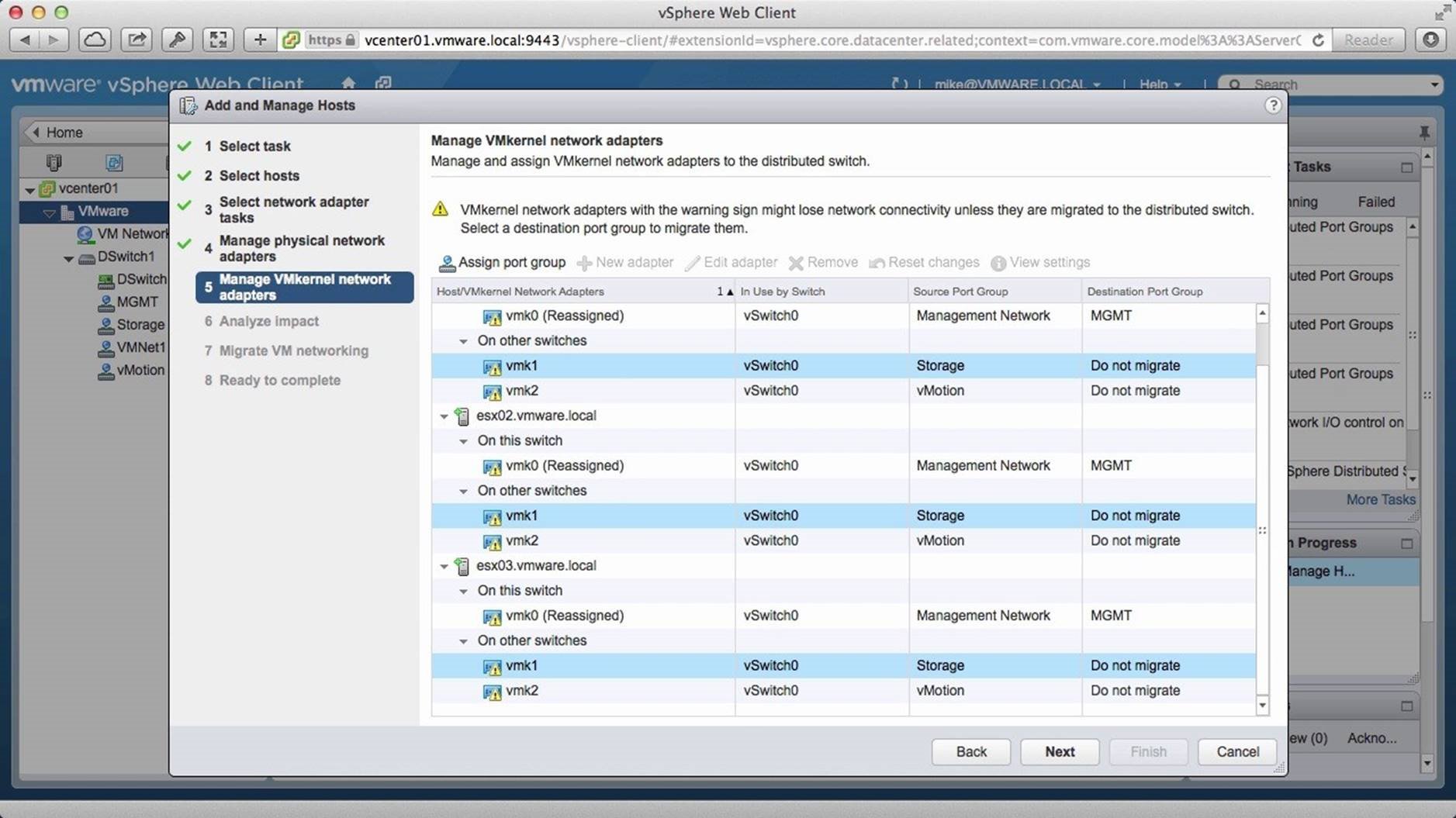
Next, we need to migrate the VMkernel NICs to the distributed switch to ensure that we do not lose connectivity. Notice that the yellow exclamation marks on the NICs indicate this. To do this, select each Kernel NIC for the traffic type and click on [Assign Port Group].
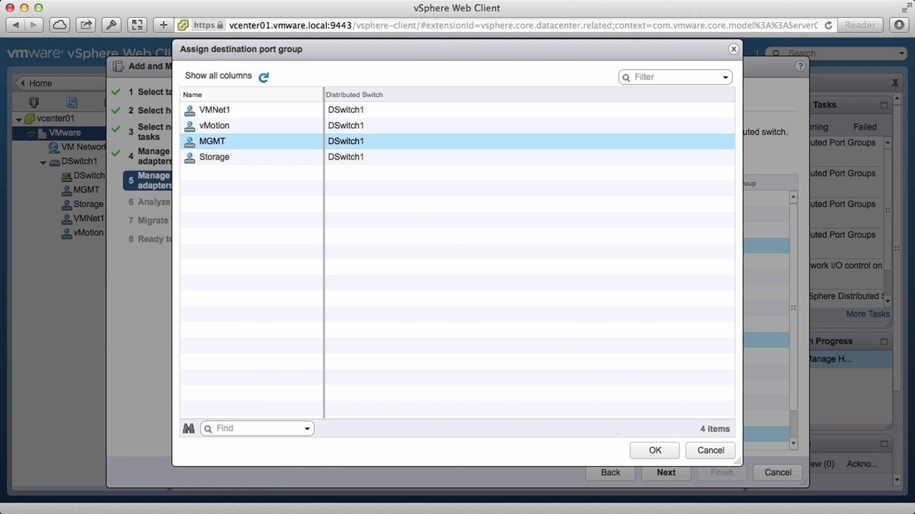
Select the appropriate distributed port group and click on [OK].
Similarly, select each storage port group and click on [Assign Port Group].
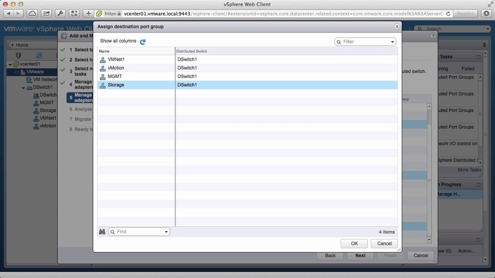
Select the appropriate port group and click on [OK].
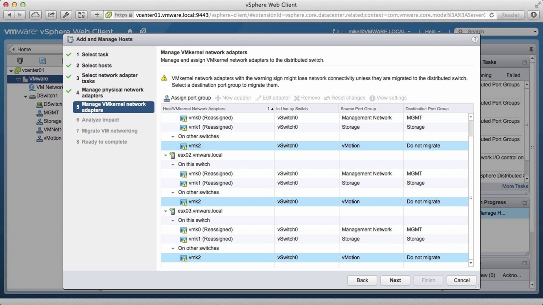
Then select each Kernel NICs associated with the vMotion port group and click on [Assign Port Group].
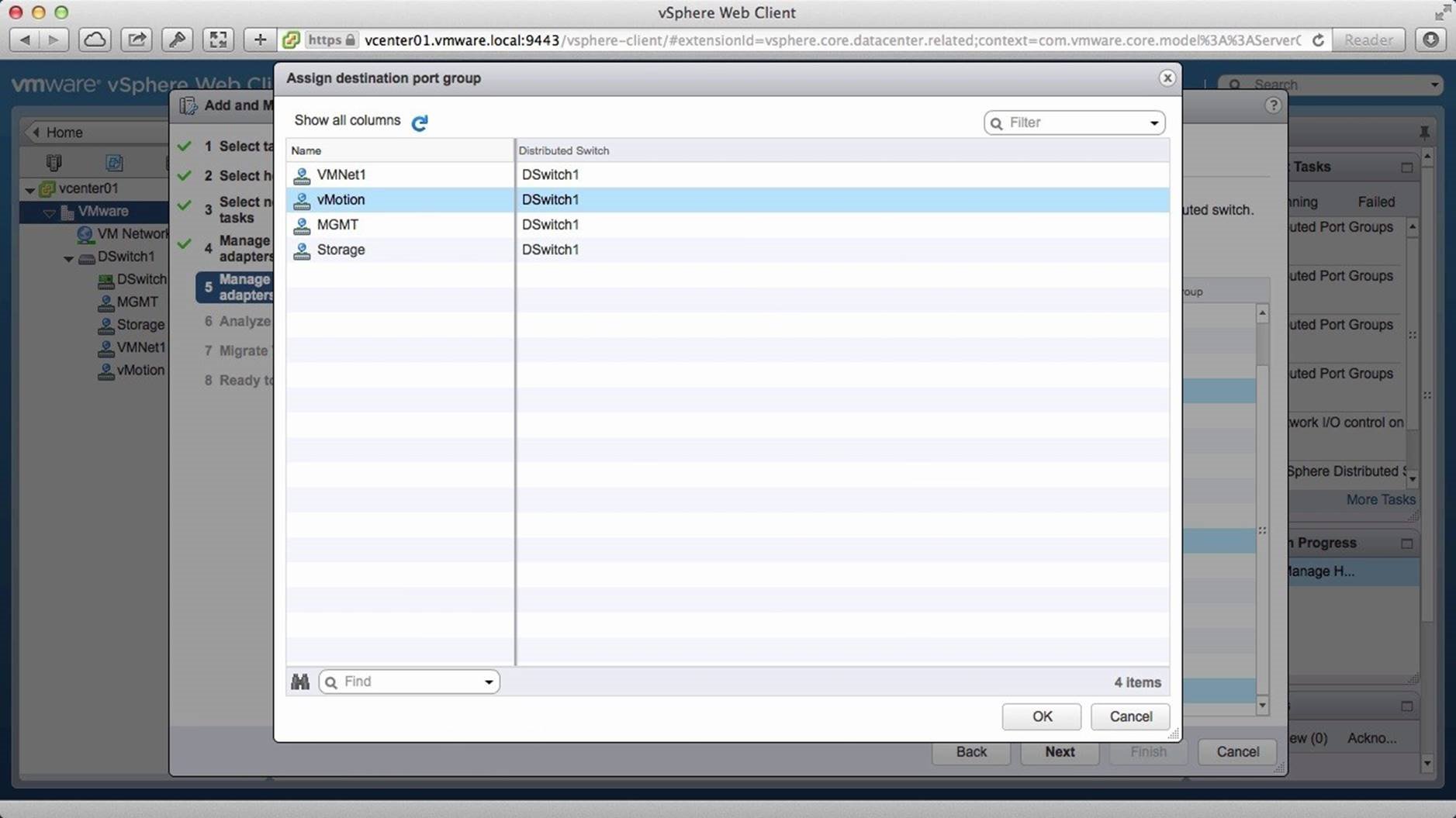
Select the port group and click on [OK].
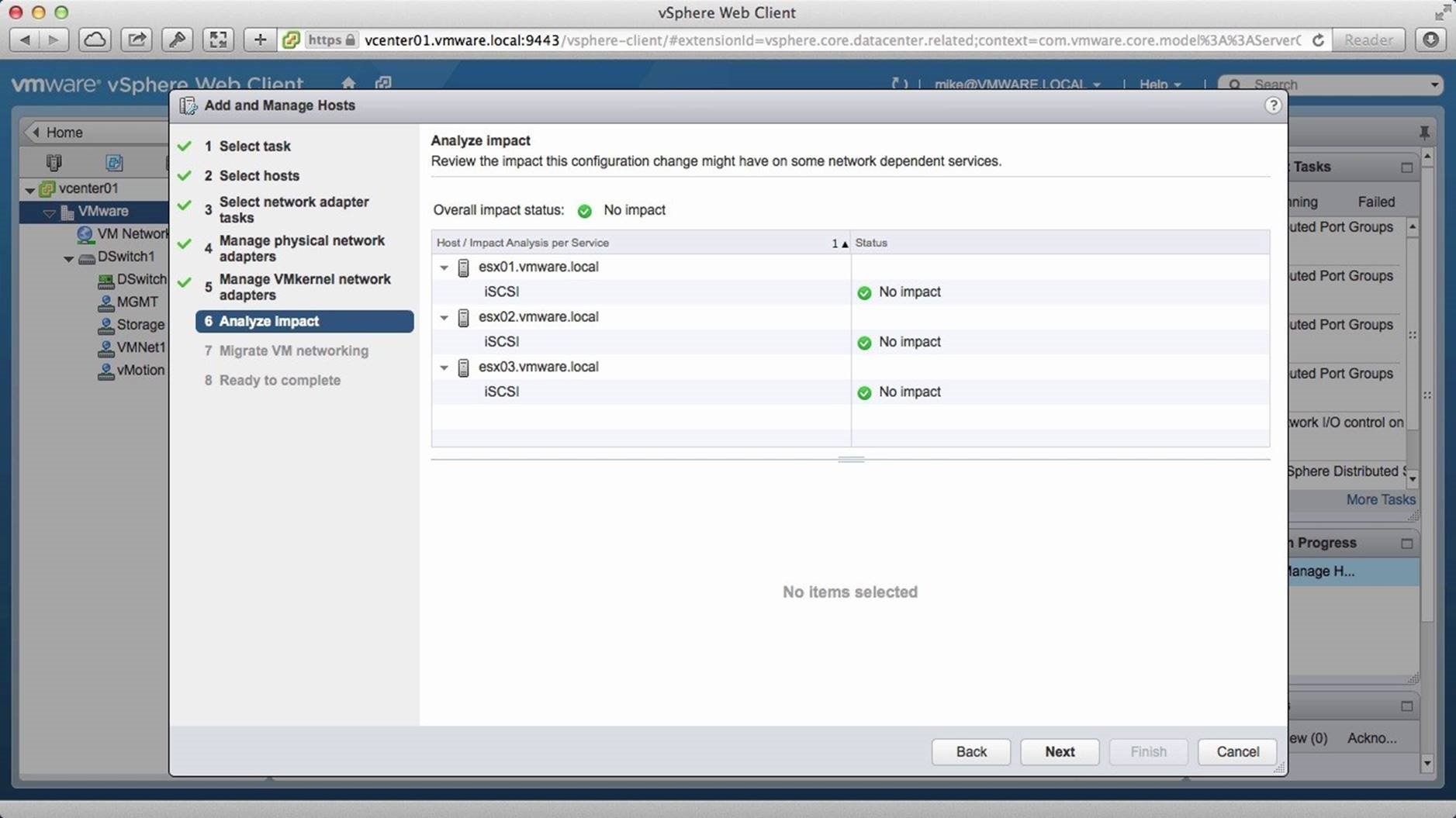
Next, we analyze the impact. We see that there is no adverse impact and we are ready to migrate. Click on [Next].

Here we select our two virtual machines and click on [Assign Port Group].
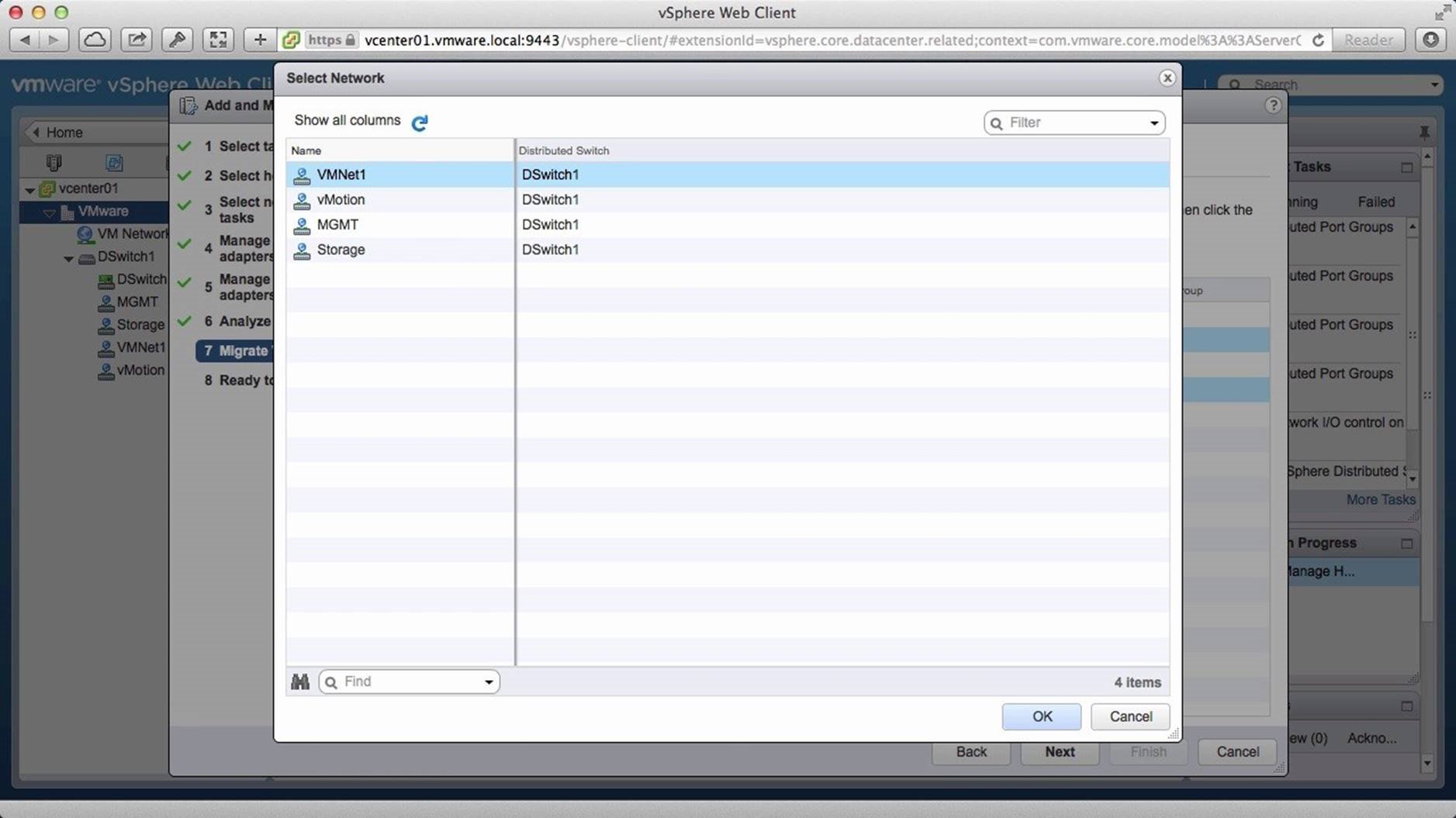
We select the [VMNet1] port group and click on [OK].
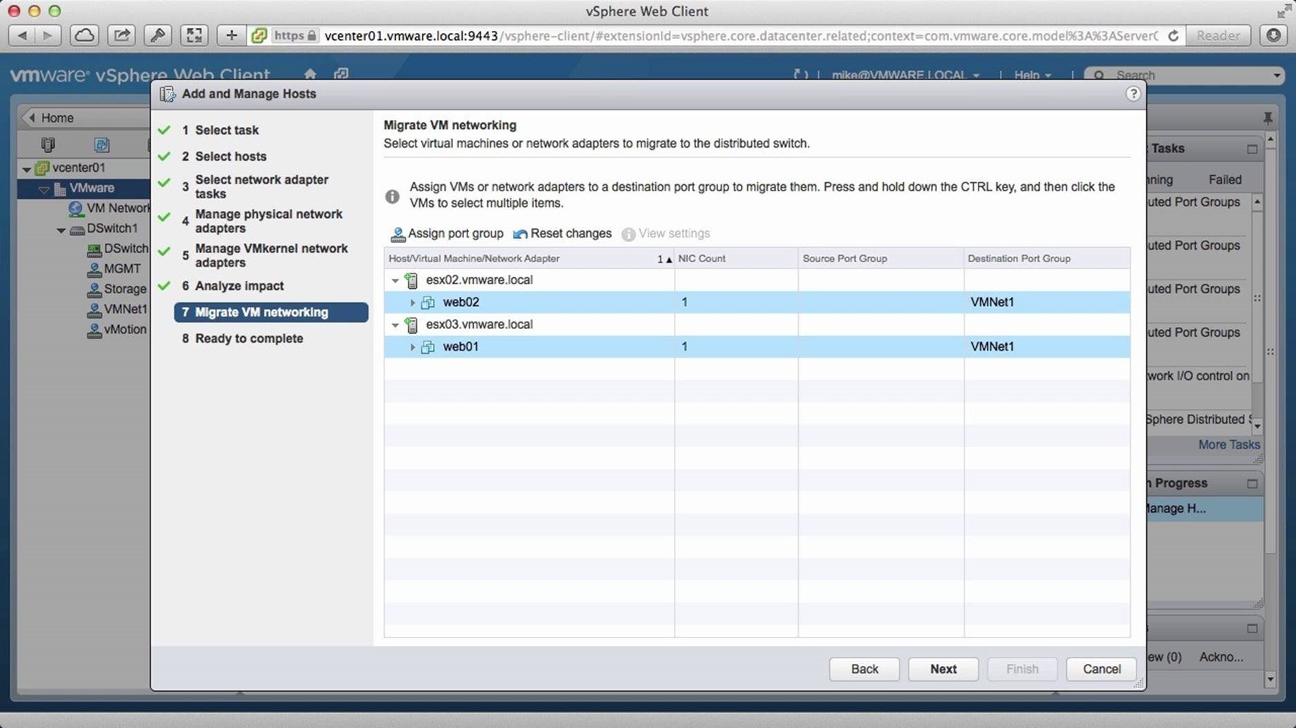
Click on [Next].
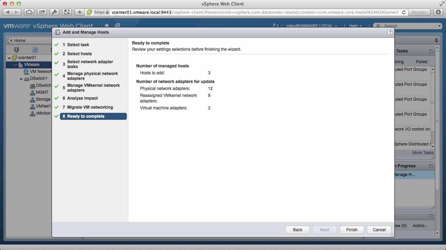
Review the information and click on [Finish].
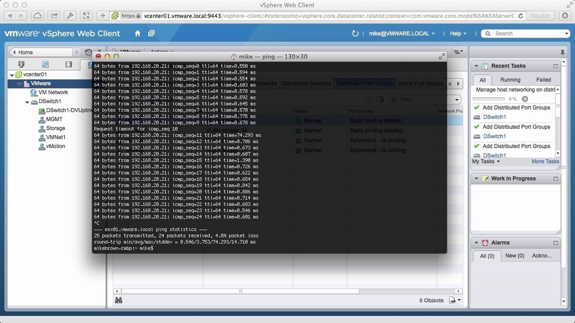
Next we start pinging our first ESX host. We see that changes have not been made and that we are still on the standard switch. After a while, we see that we miss a ping. When it resumes, we are up on the distributed switch. The significance here is the minimal downtime that was faced. With one or two missed pings, the changes have taken effect.
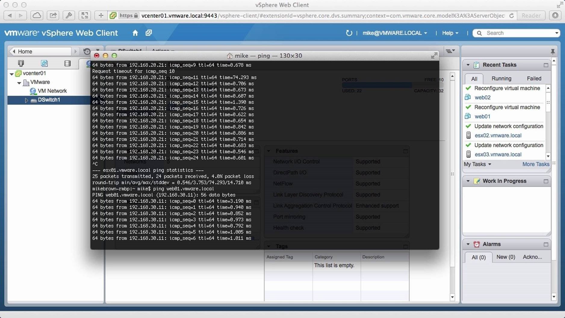
We then ping a virtual machine and see that the VM has already been migrated to the distributed switch.
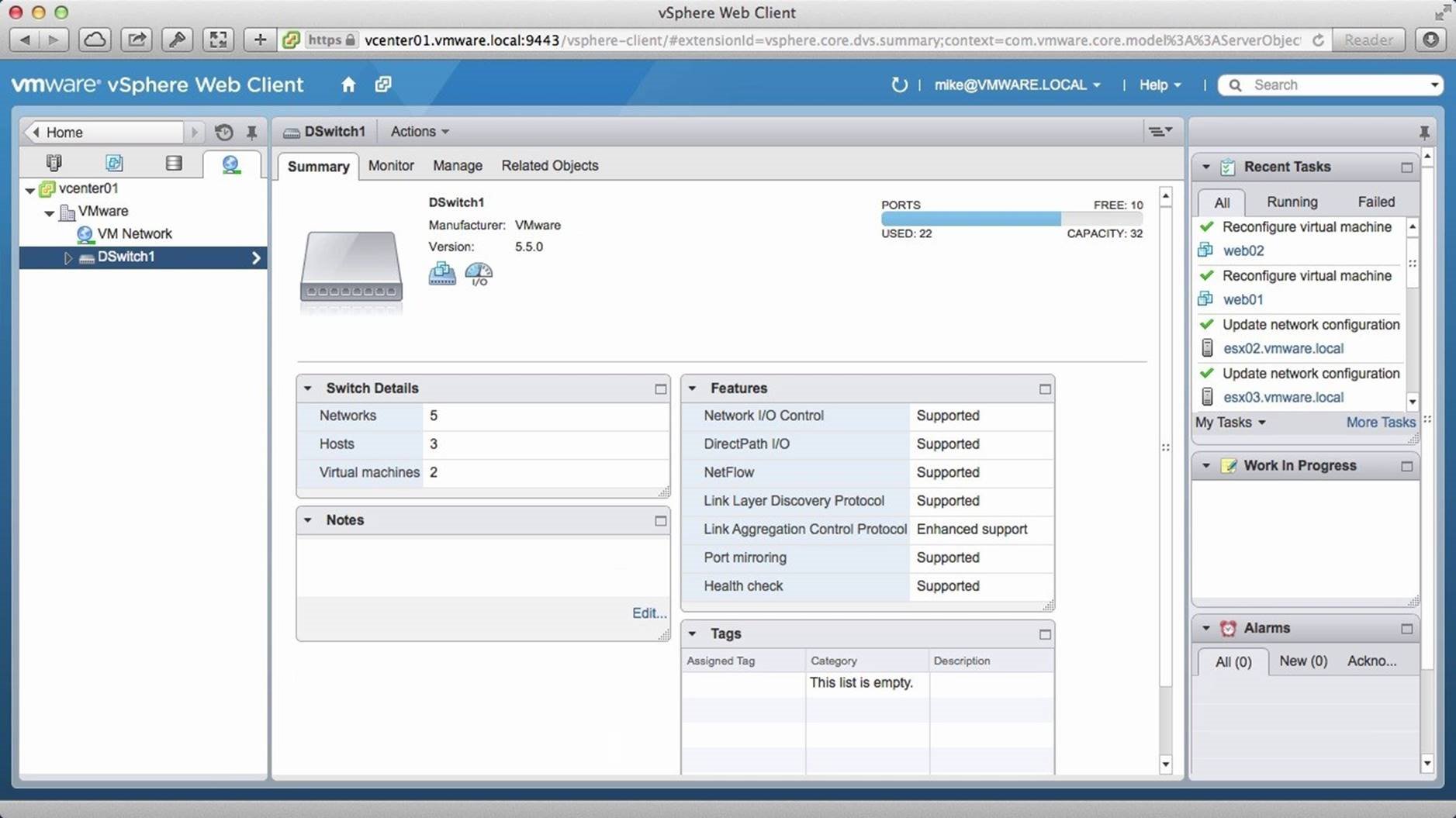
We switch back to the web client and look at the recent tasks column. We see that everything has been reconfigured. To further verify the migration completion, we go to the [Related Objects] tab.
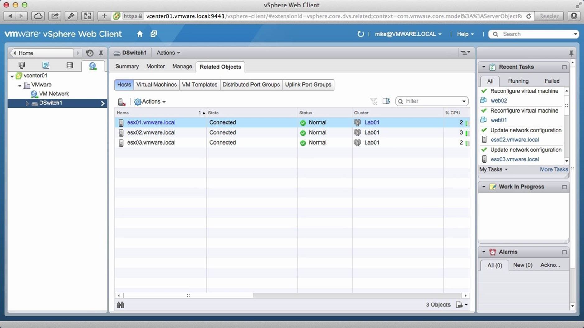
We see that all three hosts have been re-connected. We then go to the [Virtual Machines] tab.
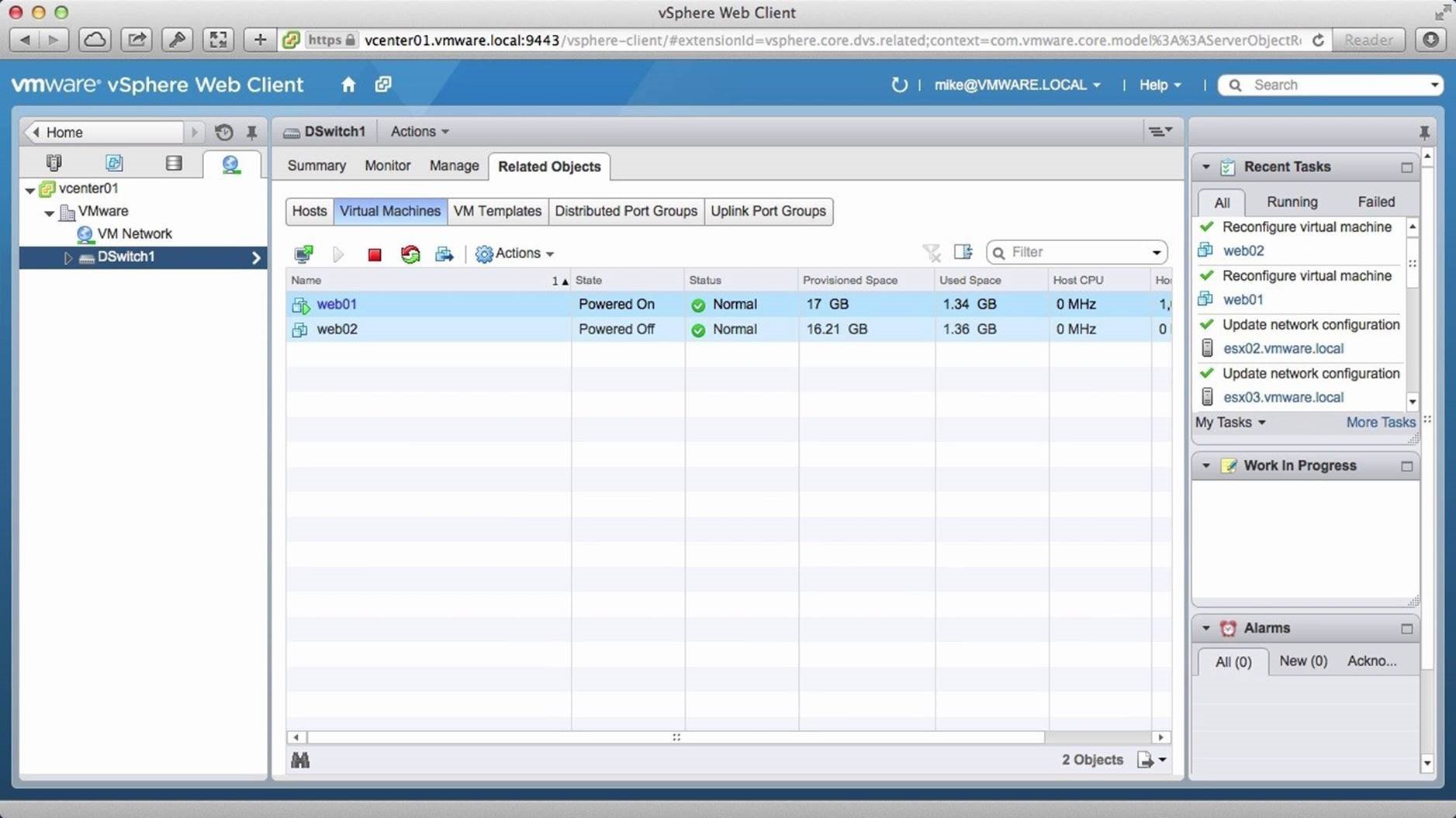
We see that the two VMs that were selected are also connected to the vSphere distributed switch. This concludes our two part demonstration on how to get started with VMware vSphere Distributed Switch. Select the next walkthrough of your choice using the navigation panel.
Backup and Restore
This walkthrough is designed to provide a step-by-step overview on how to Backup and Restore a vSphere Distributed Switch. Use arrow keys to navigate through the screens.
In this example, we will back up a distributed switch from one vCenter server and restore it to another vCenter server. Begin by logging onto the vSphere Web Client and click on [Networking].
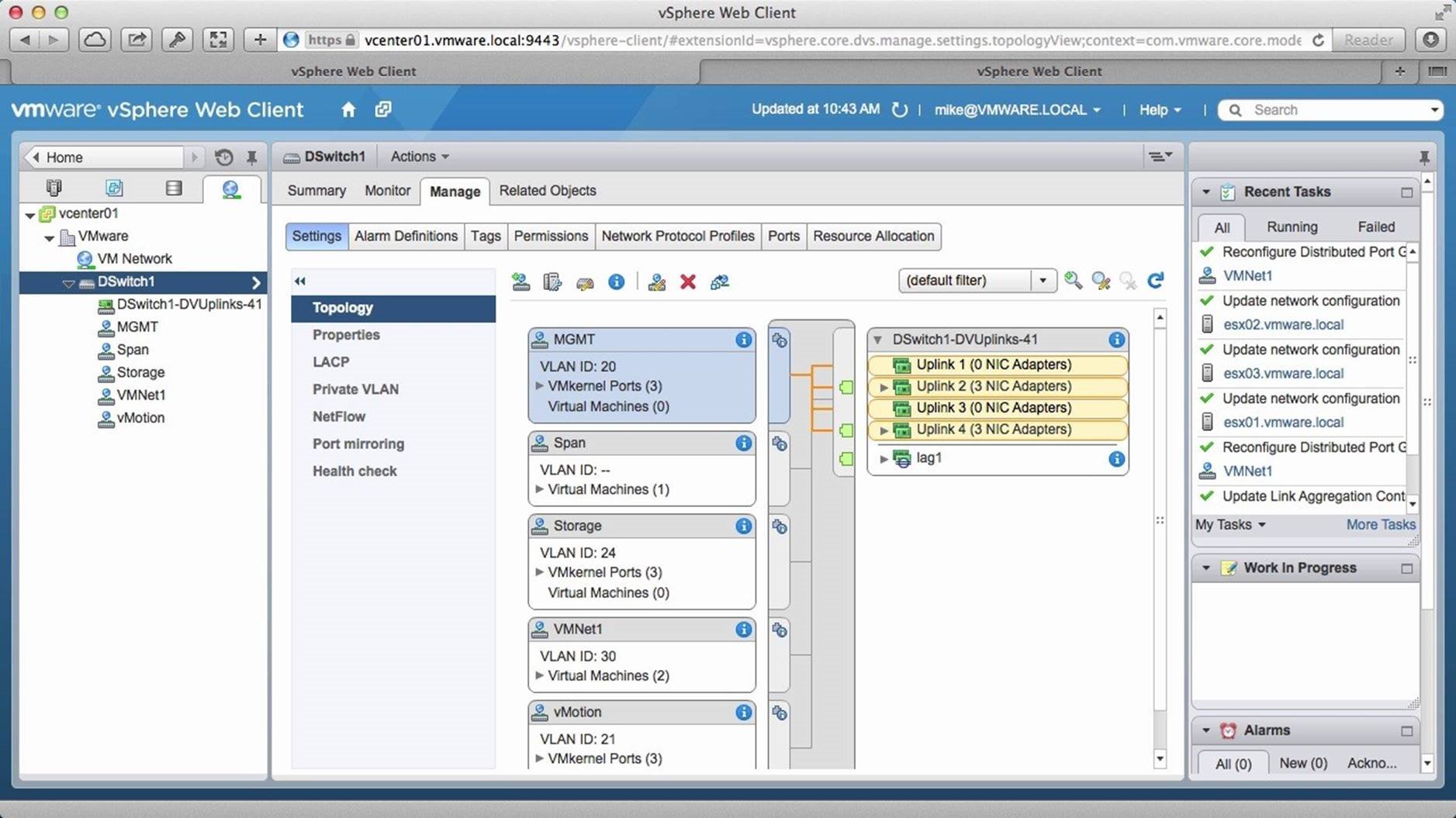
Click on the [Distributed Switch] and view the current topology. Next, right click on the [Distributed Switch].
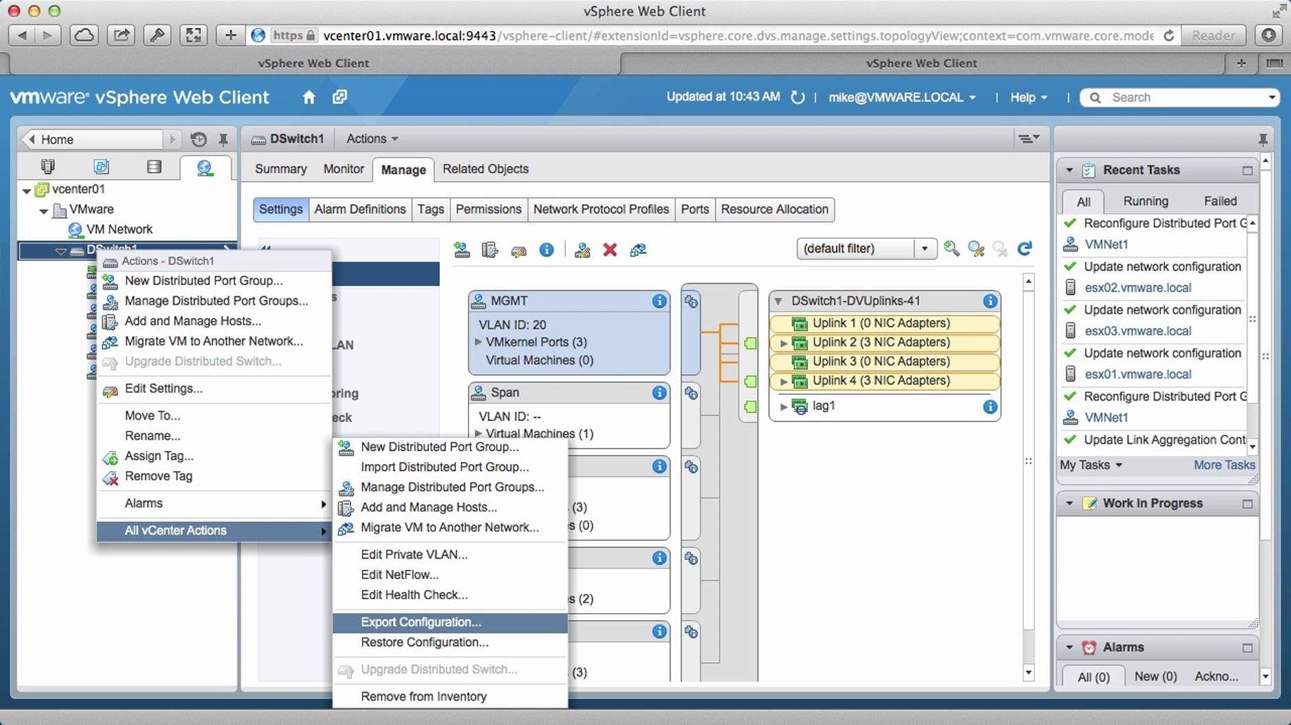
Go to [All vCenter Actions] and then click on [Export Configuration].
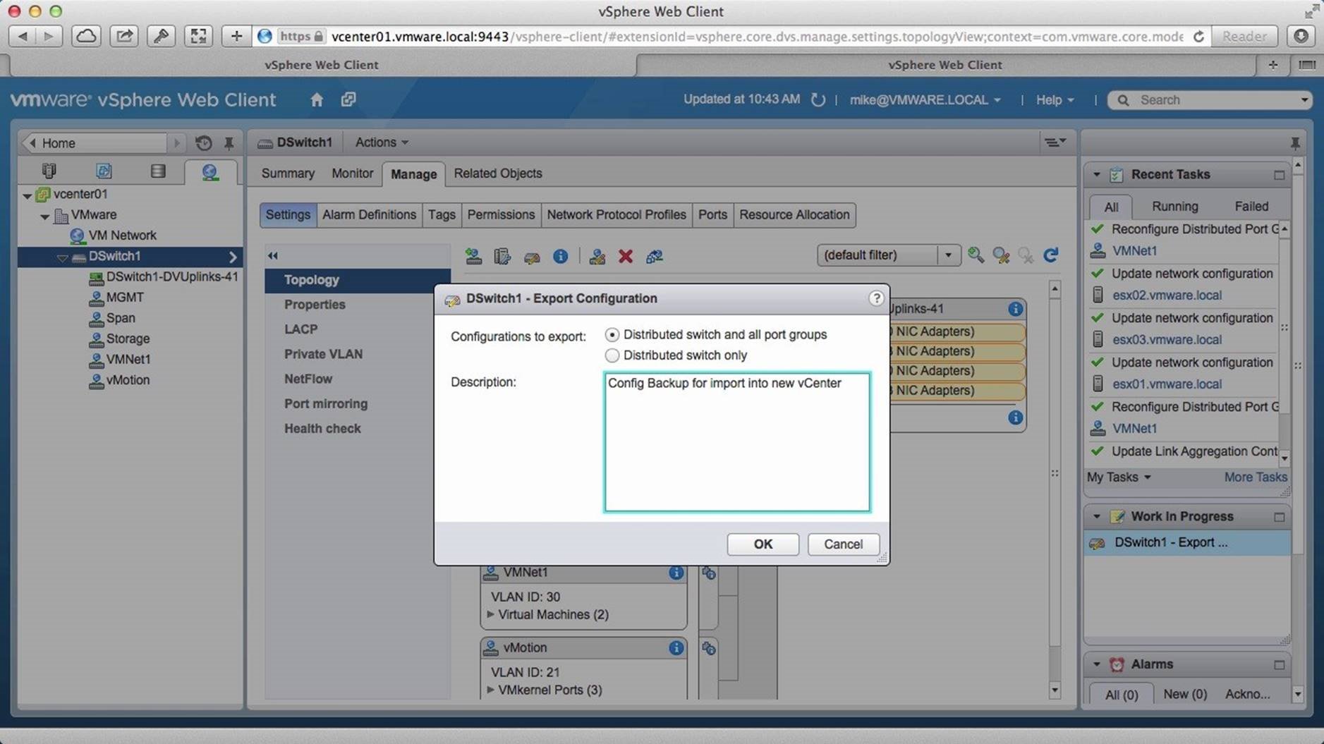
Select the type of backup you wish to perform. In this example, we retain the default selection. Provide a description for the export task and click on [OK].
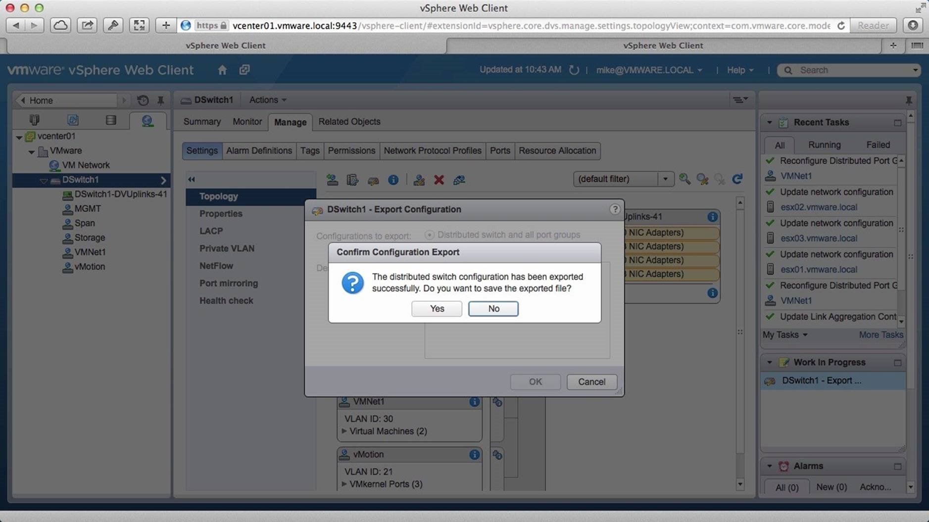
On this pop-up, click on [Yes] to save the file to your local machine.
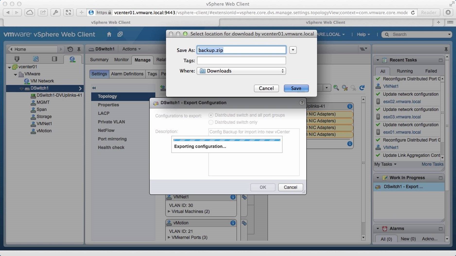
Assign a name to the backup file, select the location and click on [Save]. Note: You need to save the file as a (.zip) zipped file. Make sure that you do not change the format, because you will not be able to import the file if it is saved in a different format. The backup is captured as a binary file that cannot be edited.
Next, access a second vCenter server. In this example, we have accessed another vCenter server using the web client on another browser window and we switch to it.
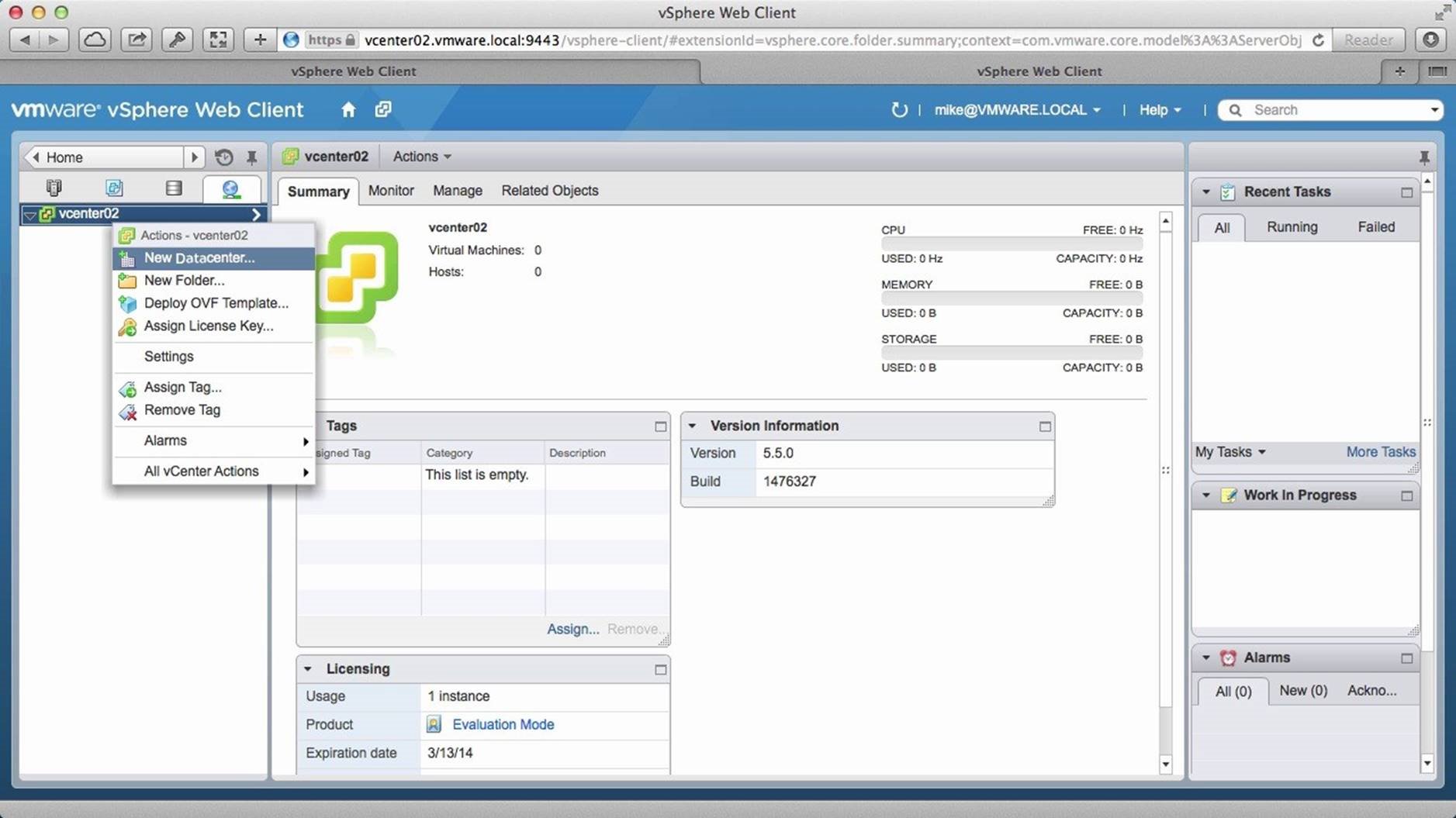
Navigate to the [Networking] section. Notice that the inventory is empty. We will first create a datacenter. Right click on the [vCenter Server] and click on [New Datacenter].
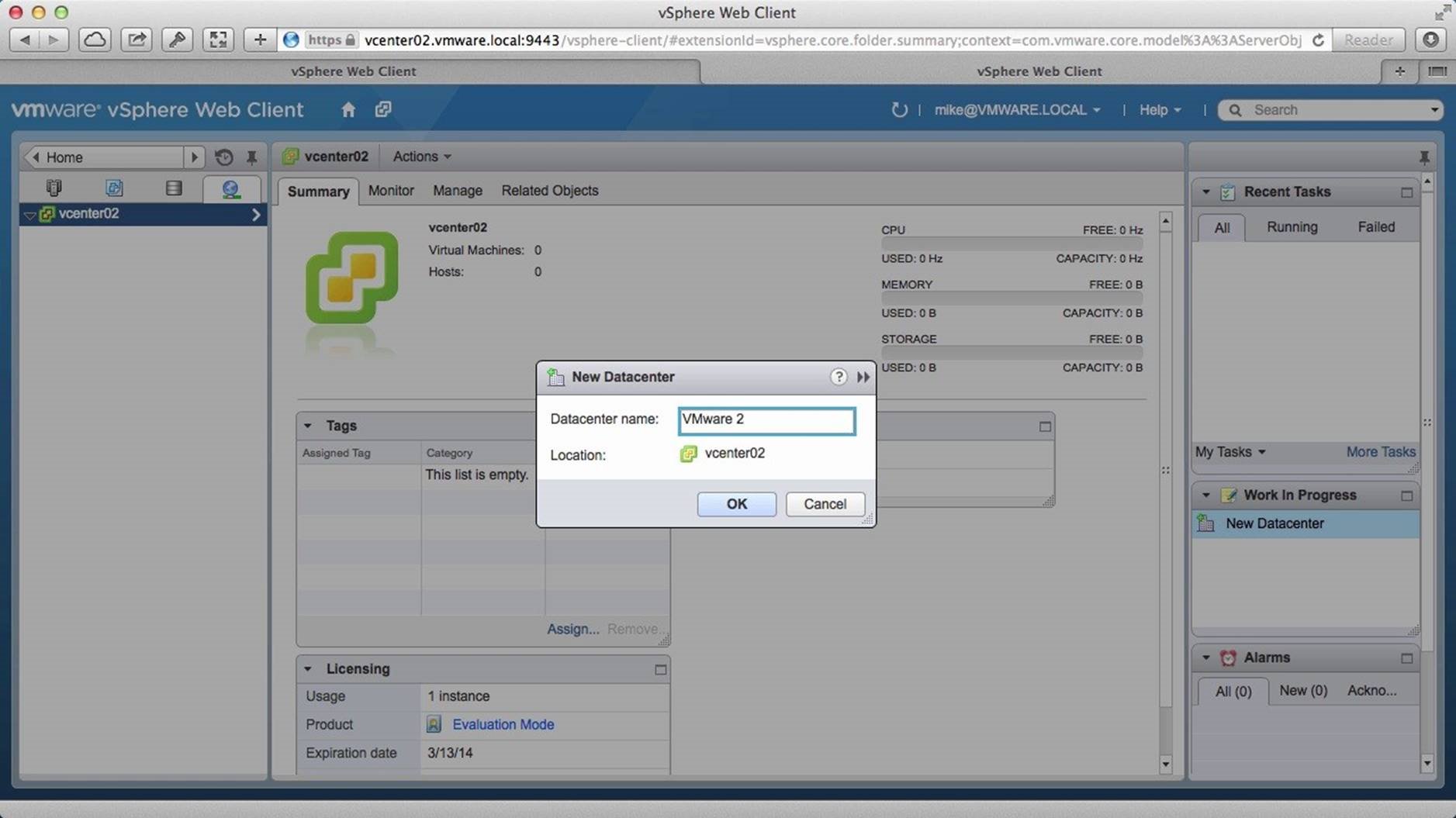
Assign a name to the datacenter and click on [OK]. Note: The VDS is the datacenter object and any host inside that datacenter can use that distributed switch.
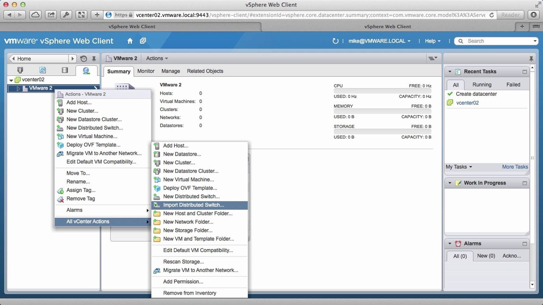
The datacenter object has been created. We can go ahead and import the backed up distributed switch. Right click on the [Datacenter] object, go to [All vCenter Actions] and click on [Import Distributed Switch].

Click on [Browse] to select the backup file.
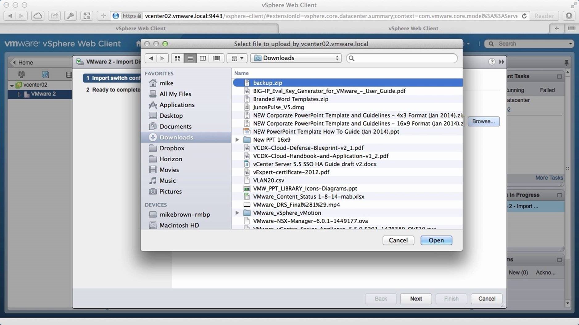
Locate and select the backup zipped file. In this example, the file was named [Backup.zip], so we select it and click on [Open].
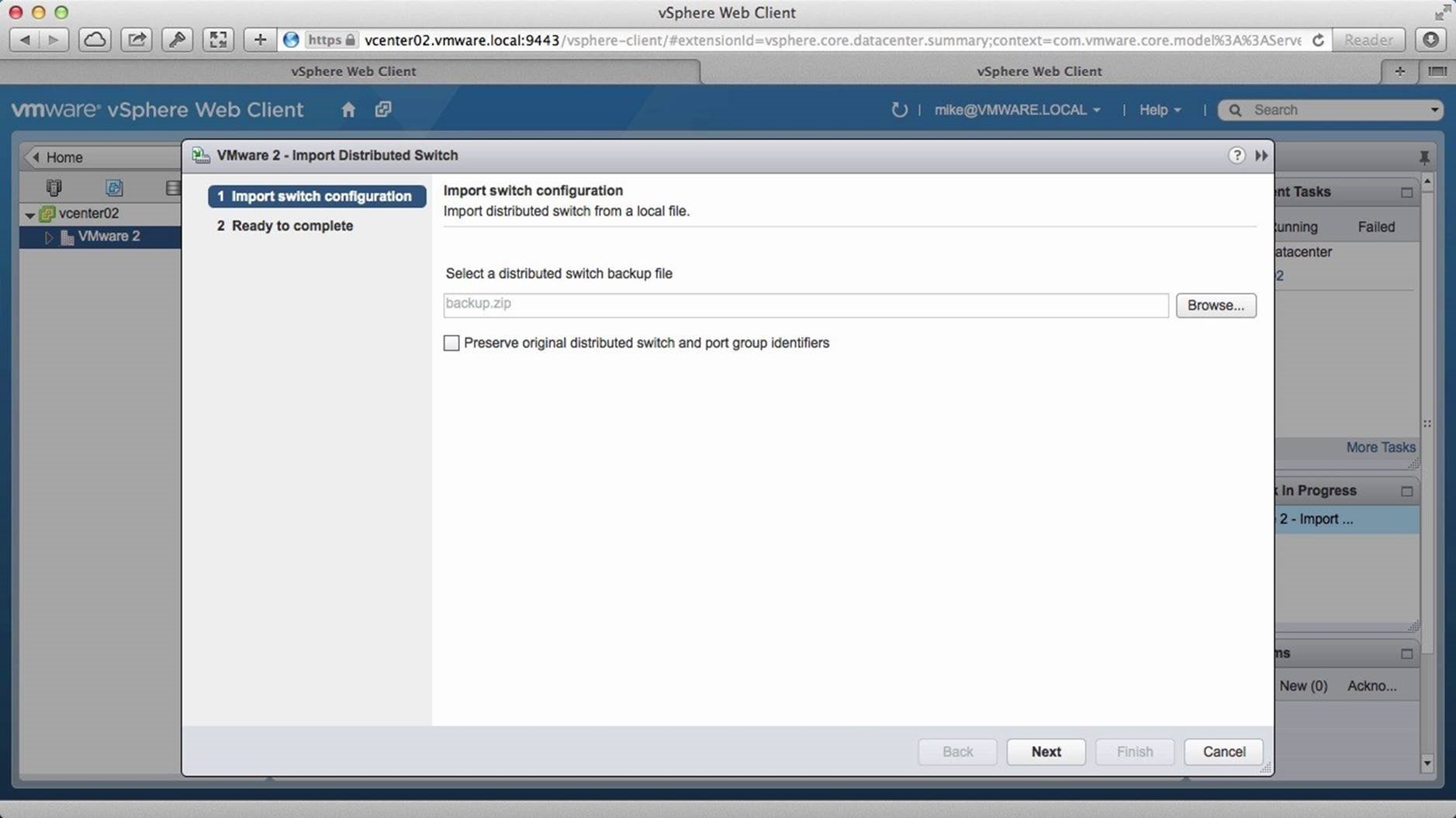
Click on [Next].
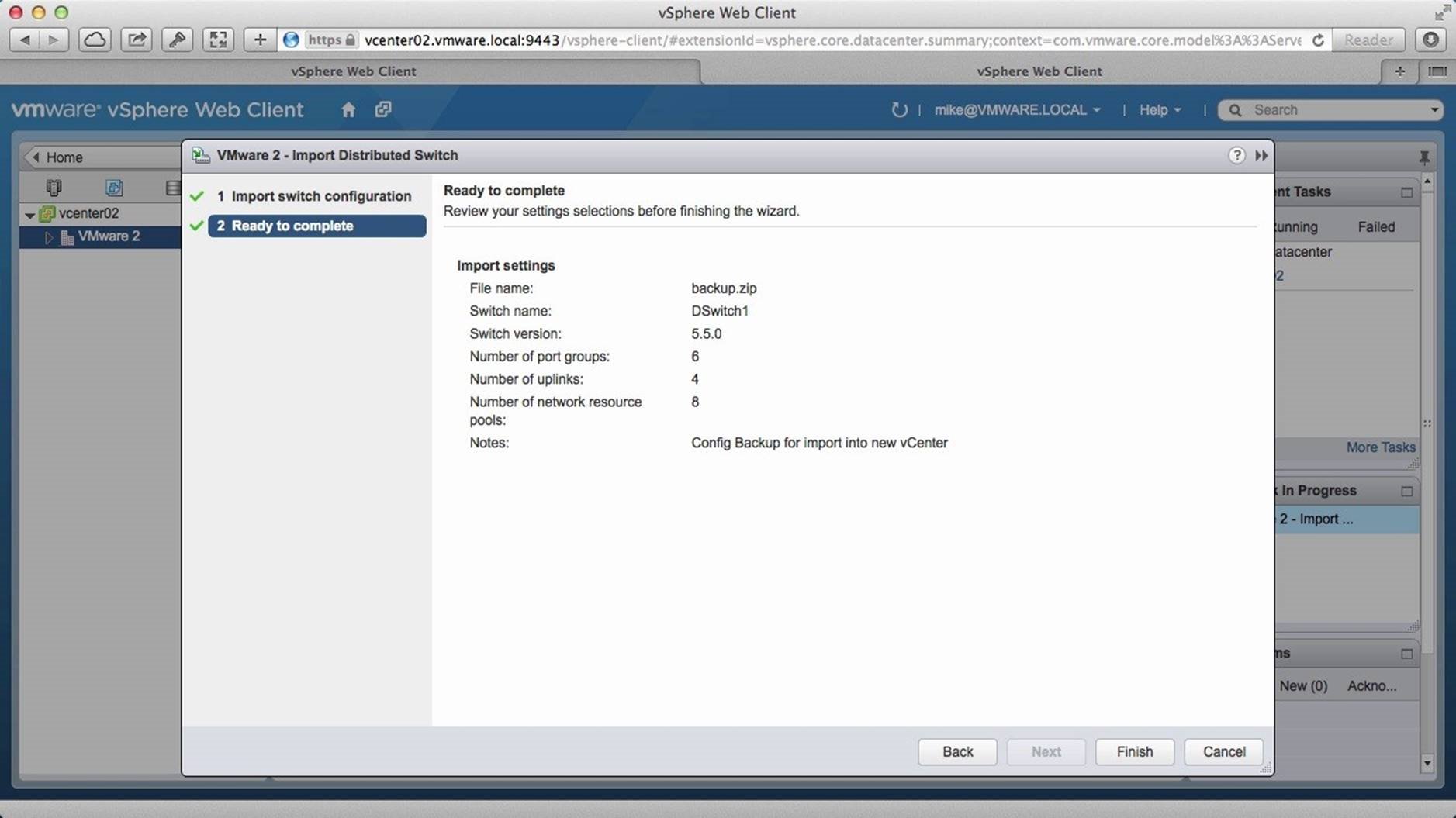
Verify the information and click on [Finish]. This will import the configuration which we just exported from vCenter01 into vCenter 02.
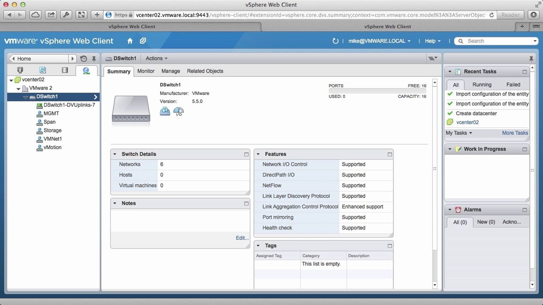
Once the task has been successfully completed, we see the distributed switch in the inventory along with all the port groups that are a part of the distributed switch we first exported. Next we go into the [Manage] tab.
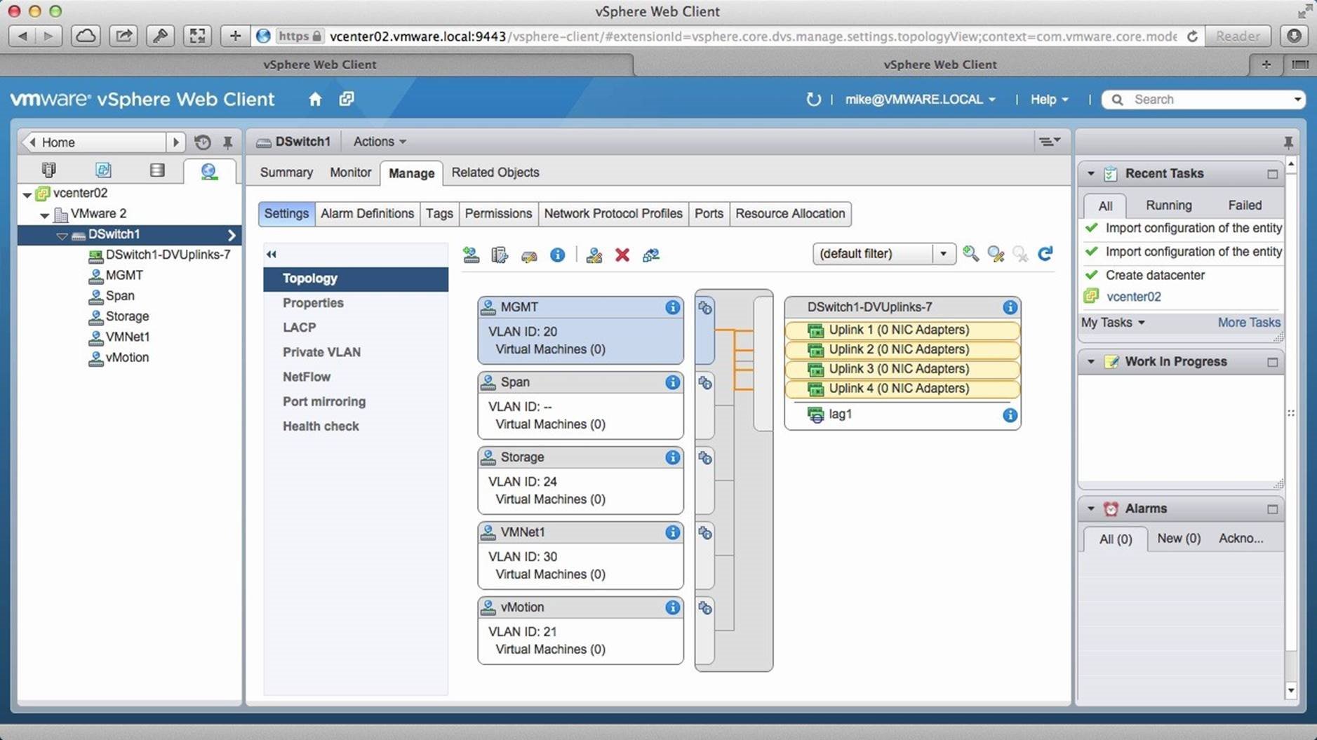
Notice that we have all the port groups, uplinks and the LAG listed. Another feature of the backup and restore functionality is the ability to recover a single port group. To demonstrate this, we switch back to the first vCenter server
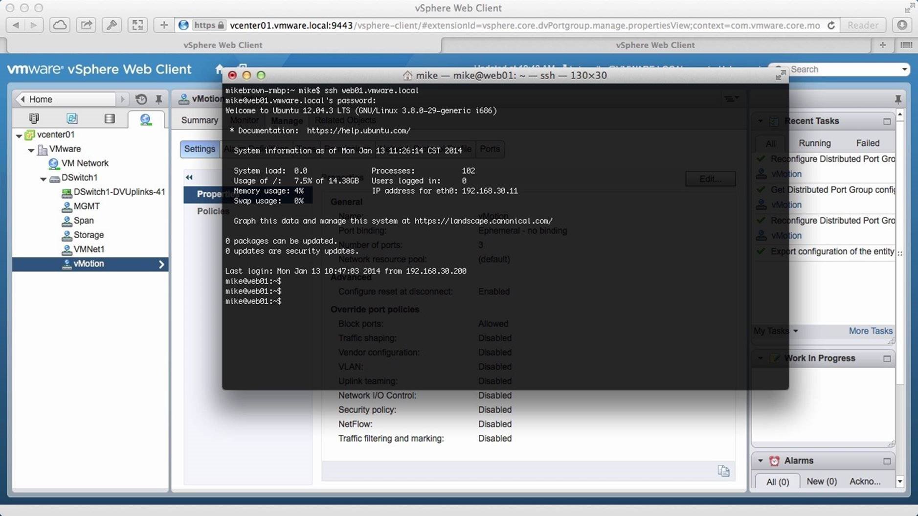
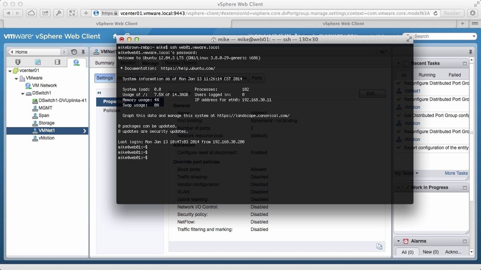
Using a secure shell we connect to our virtual machine “web01.vmware.local”, which is on the VMNet1 port group. We verify that the connection is successful. We will now make a change that inadvertently interrupts network communication and demonstrate how easily we can revert that. We switch back to the web client.
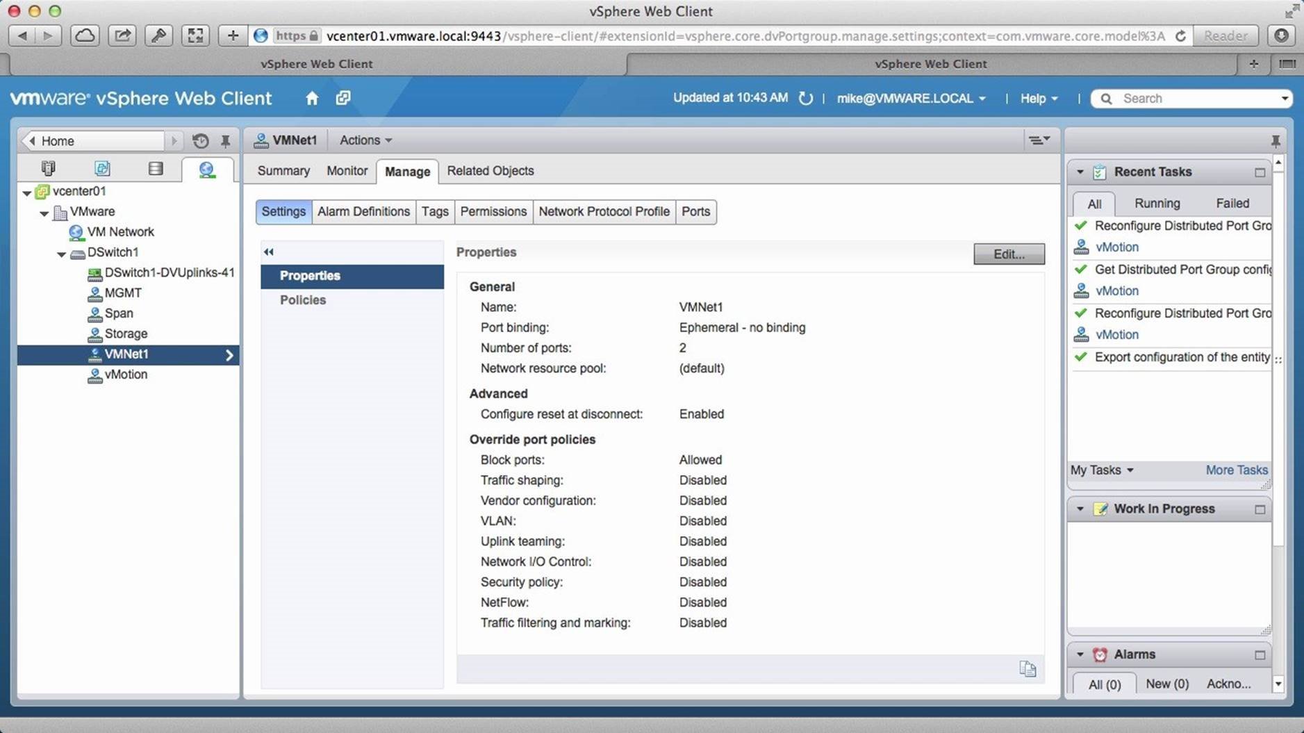
Select the [VMNet1] port group and click on [Edit].
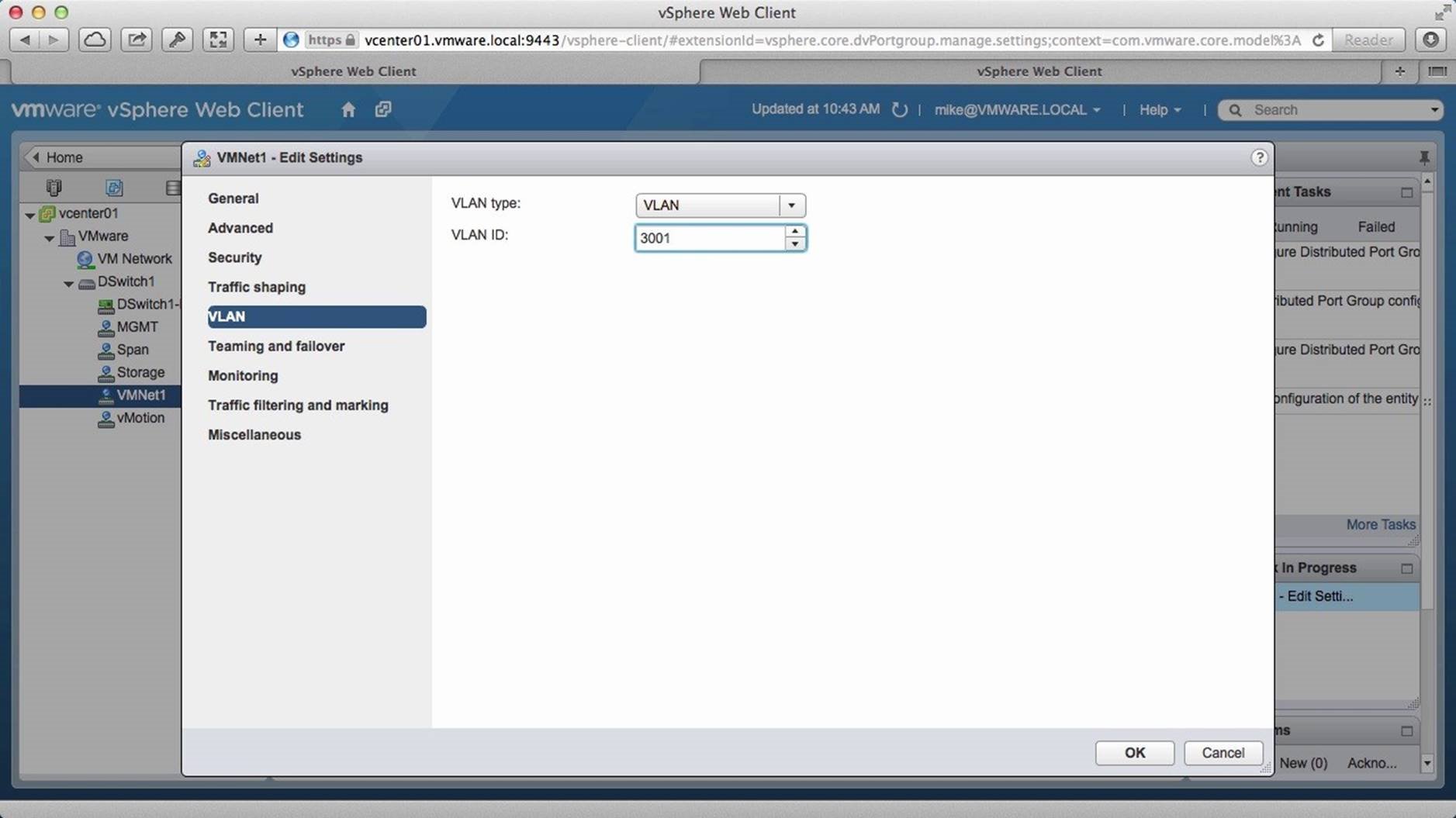
We change the VLAN ID from 30 to 3001 and click on [OK]. This will interrupt the network.
We switch back to the console and see that the SSH session has been locked up and is unresponsive now because of the change we that was done.
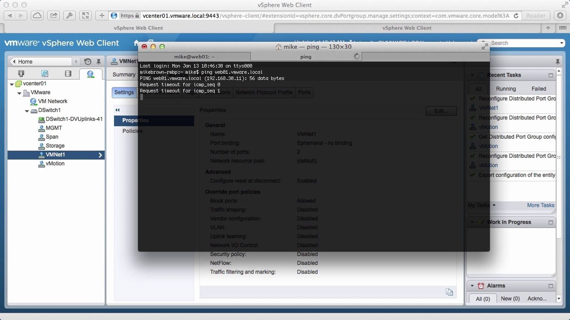
We launch a new console window and ping the VM. Notice that the connection requests are timing out as expected.
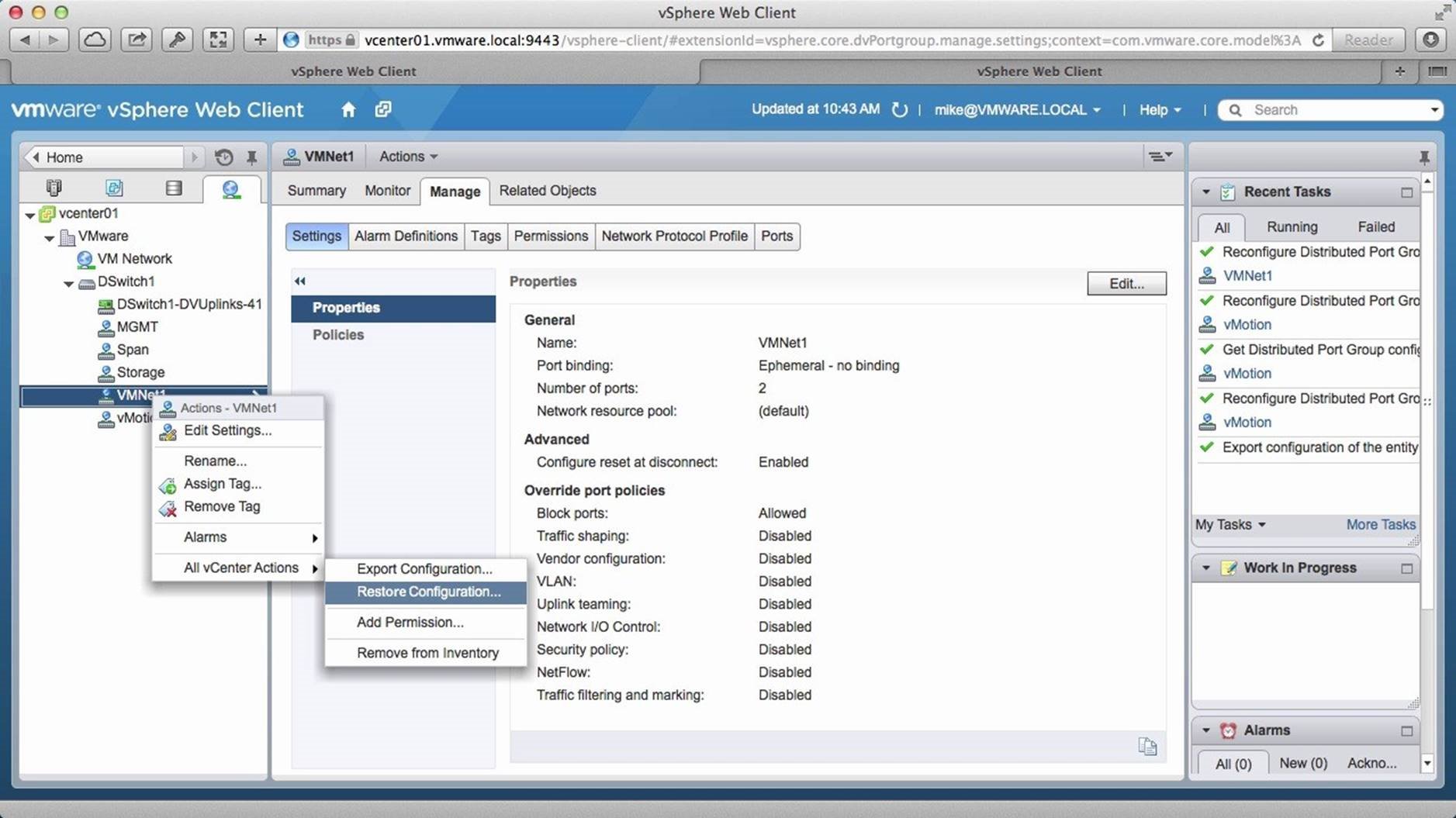
To restore the port group to its previous state, we right click on [VMNet1], go to [All vCenter Actions] and click on [Restore Configuration].
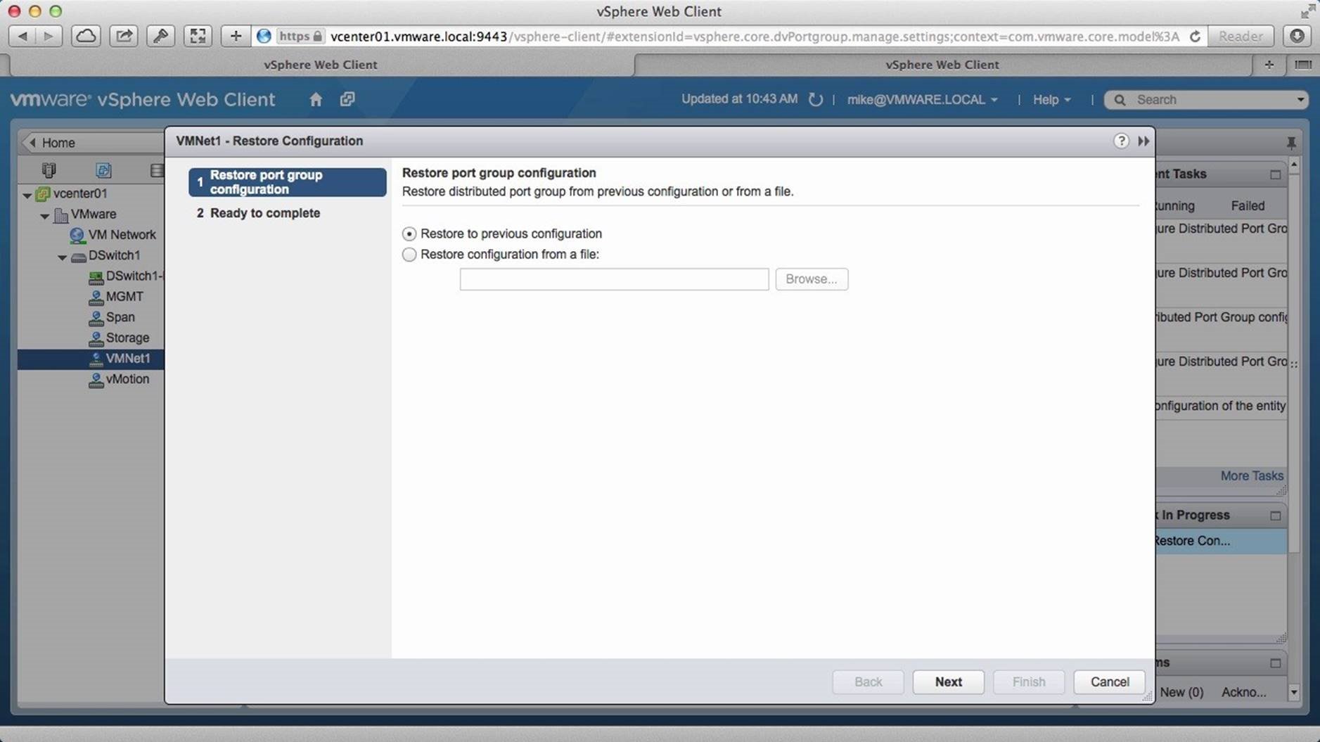
Select [Restore to Previous Configuration] and click on [Next].
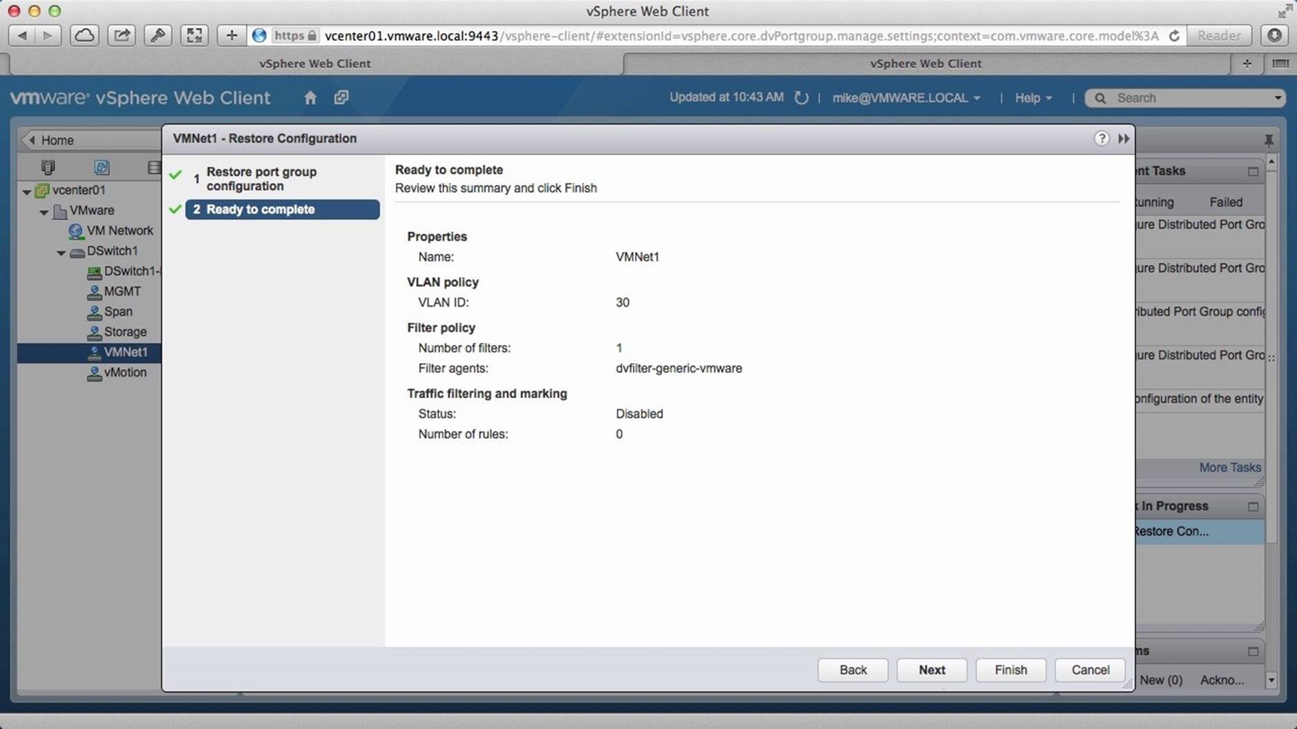
Click on [Finish]. This will revert back the change that was done.
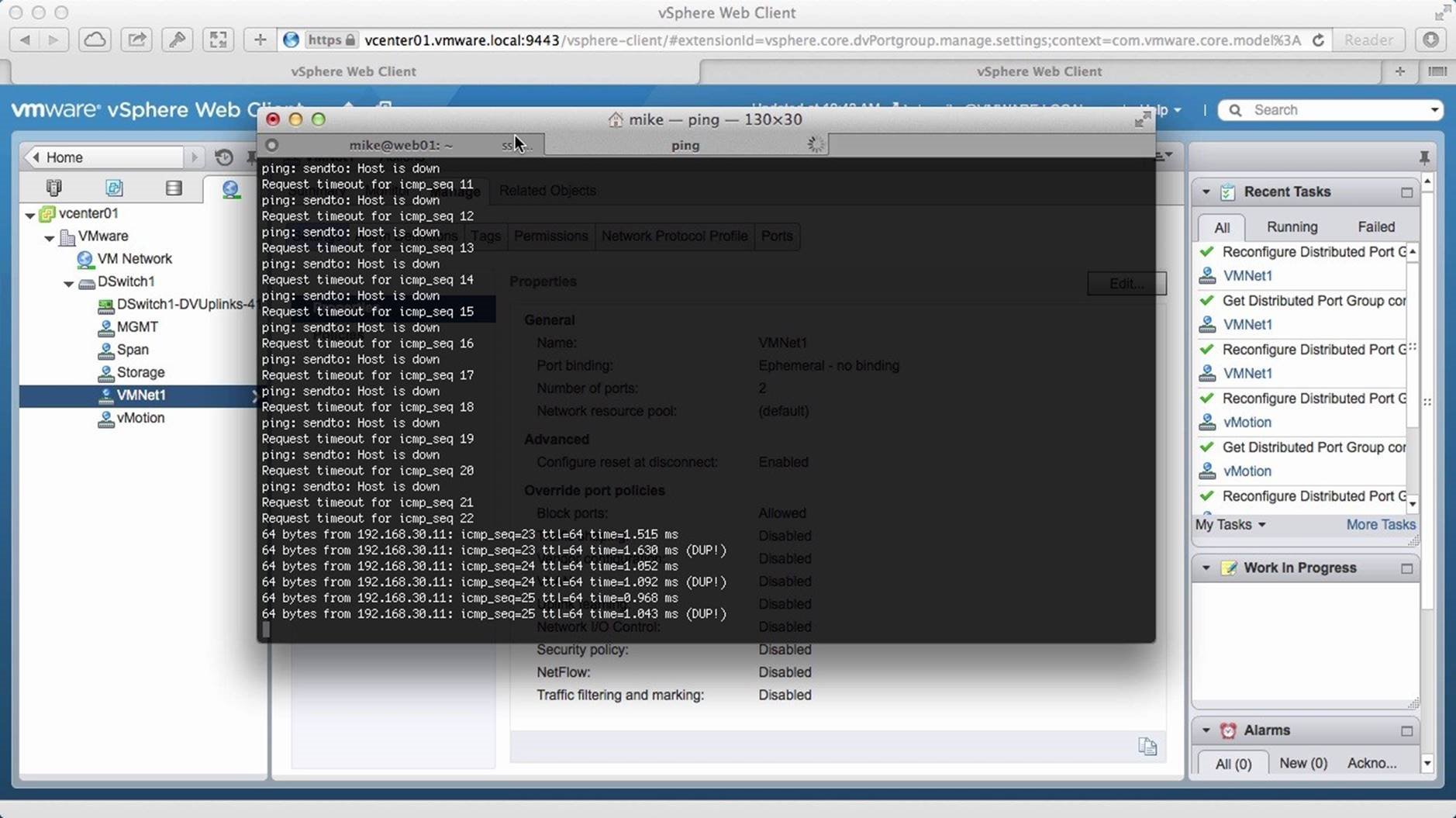
Once that is done, we see that the pings start to return responses.
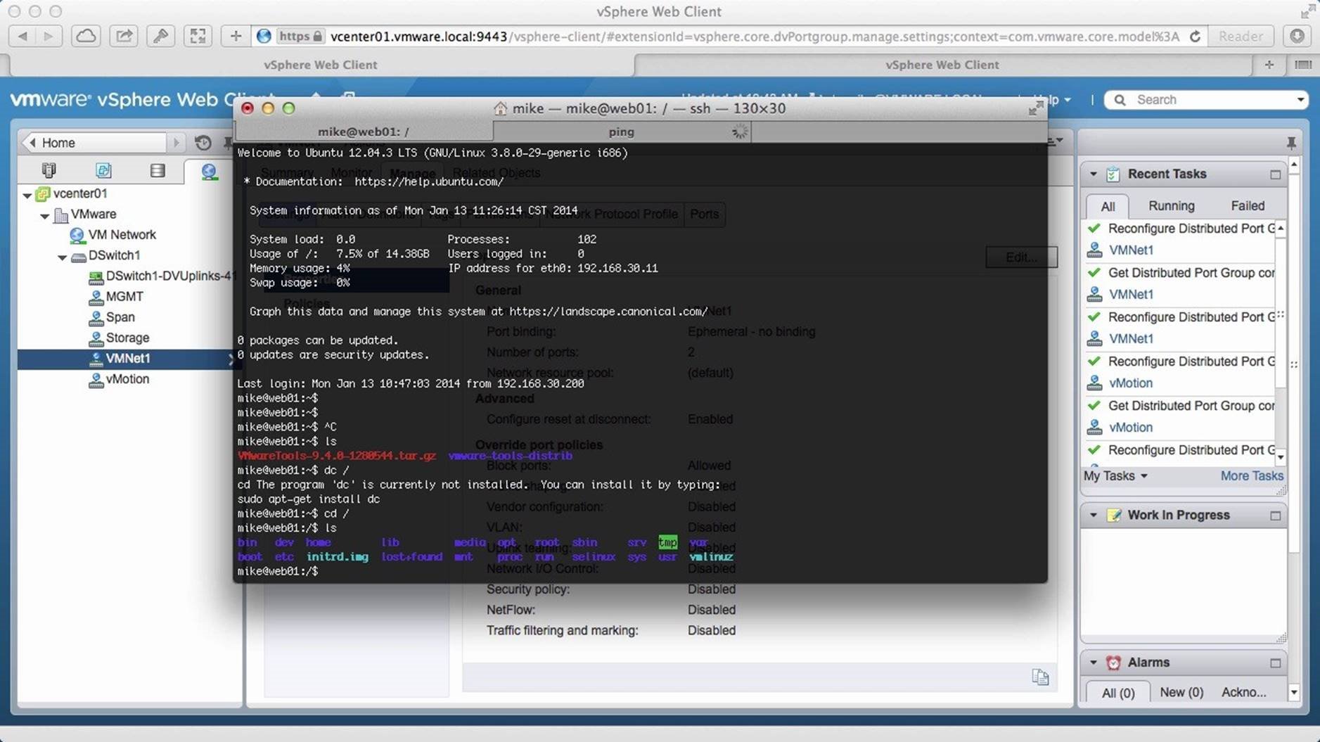
We switch to our first console window and see that it is also active and responsive again. This concludes the walkthrough on how to Backup and Restore a vSphere Distributed Switch. Select the next walkthrough of your choice using the navigation panel.
Traffic Filtering

This walkthrough is designed to provide a step-by-step overview on how to configure Traffic Filtering using the vSphere Distributed Switch. Use arrow keys to navigate through the screens.
Traffic filtering refers to the ability to allow or disallow different types of traffic. vSphere Distributed Switch can also pass class of service information on to a physical switch with Traffic Filtering. Begin by logging on to vSphere Web Client and navigate to the [Networking] section.
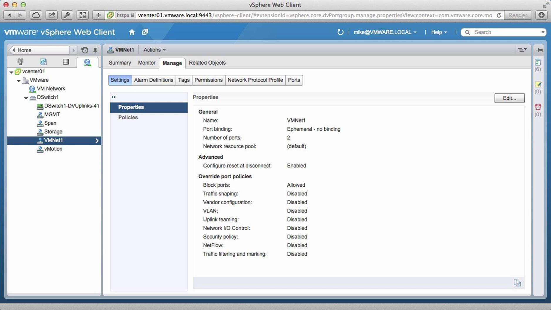
Click on a port group that is on the distributed switch. In this example, we select [VMNet1]. Click on [Manage] and click on [Edit].
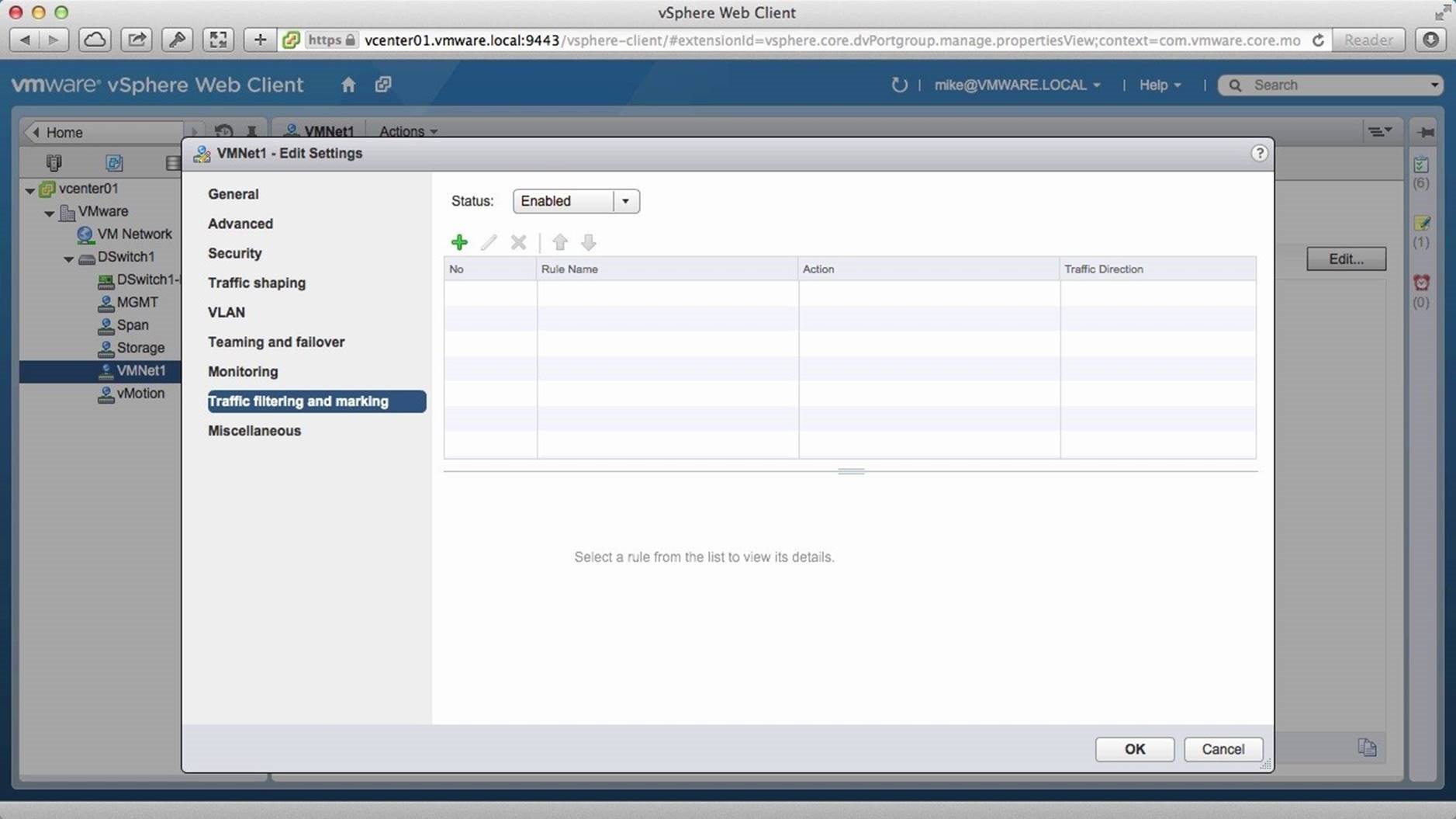
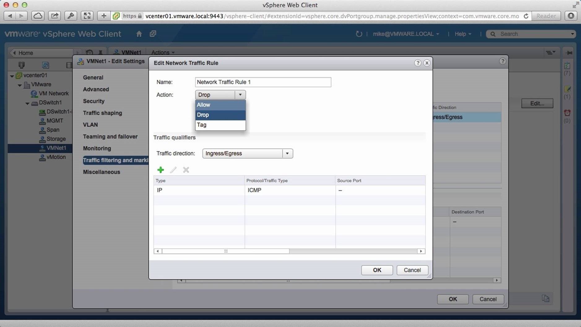
Click on [Traffic Filtering and Marking], and then change the Status to [Enabled]. Then click on the Add [+] icon to set the filtering rule.
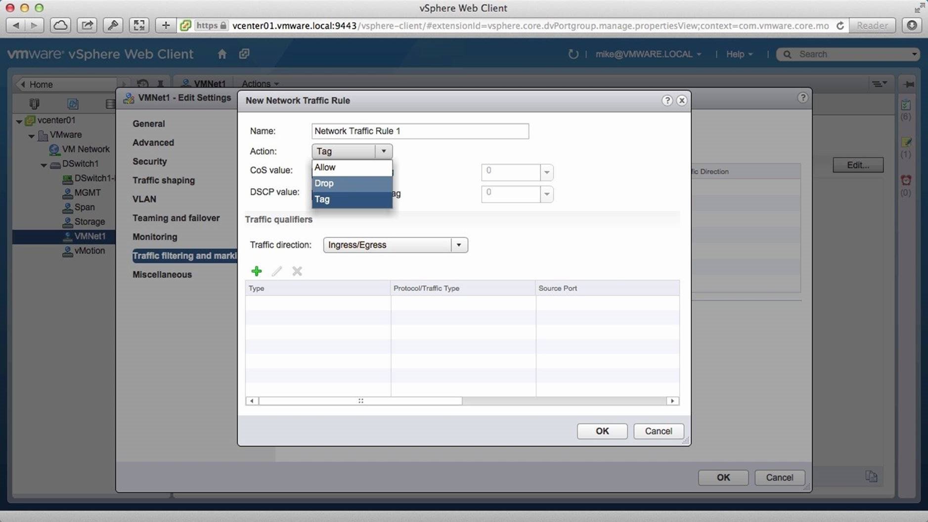
By default, “Tag” is selected as the preferred action. Change it to [Drop] so as to add an access control list to the port group.
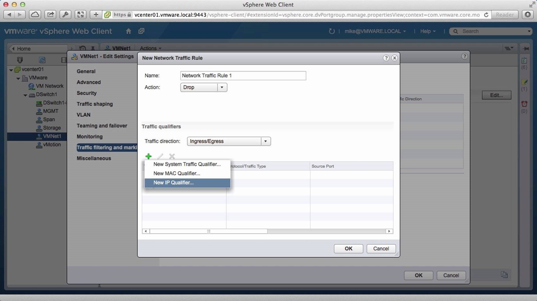
Select the type of traffic direction preferred, here we retain the default selection. Then click on the Add [+] icon and click on [New IP Qualifier].
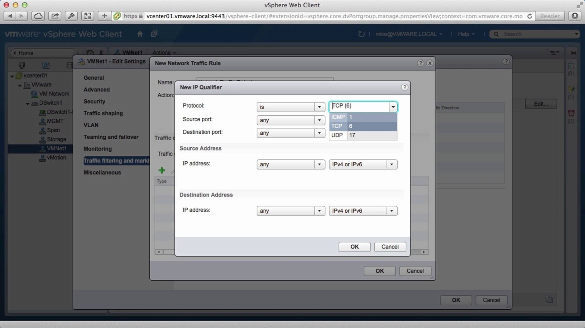
Here you have options to change protocols, source ports and destination ports. We change the Protocol from TCP(6) to [ICMP (1)].
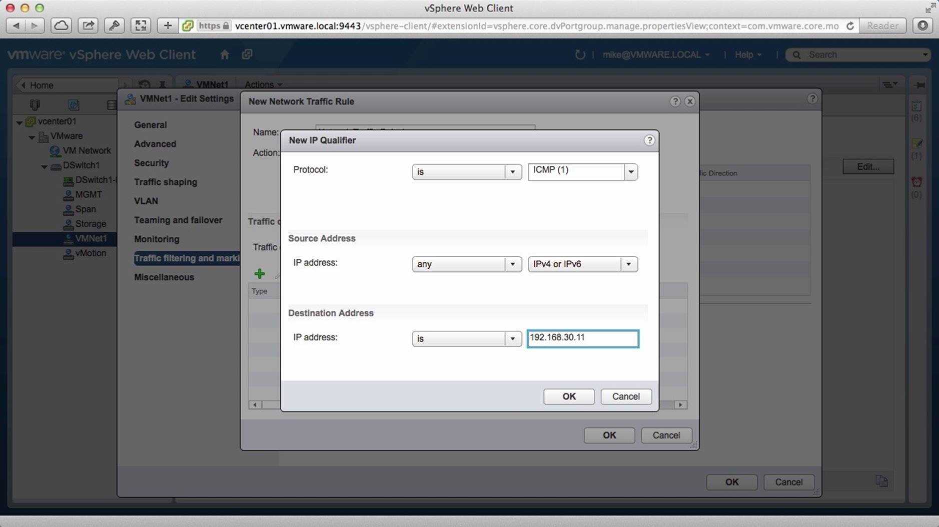
In this example, we retain the default Source Address and change the Destination Address. We enter the IP address of a server named Web01, apply the changes and click on [OK].
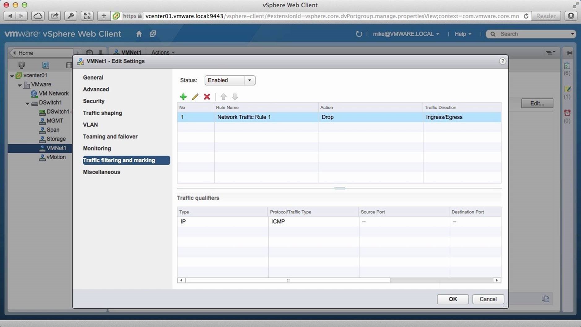
The new qualifier has been successfully created. Click on [OK].
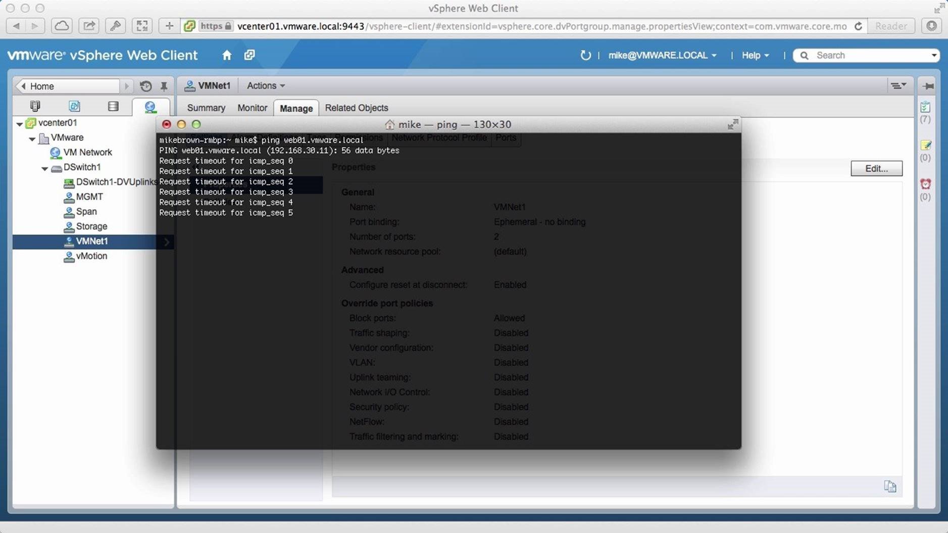
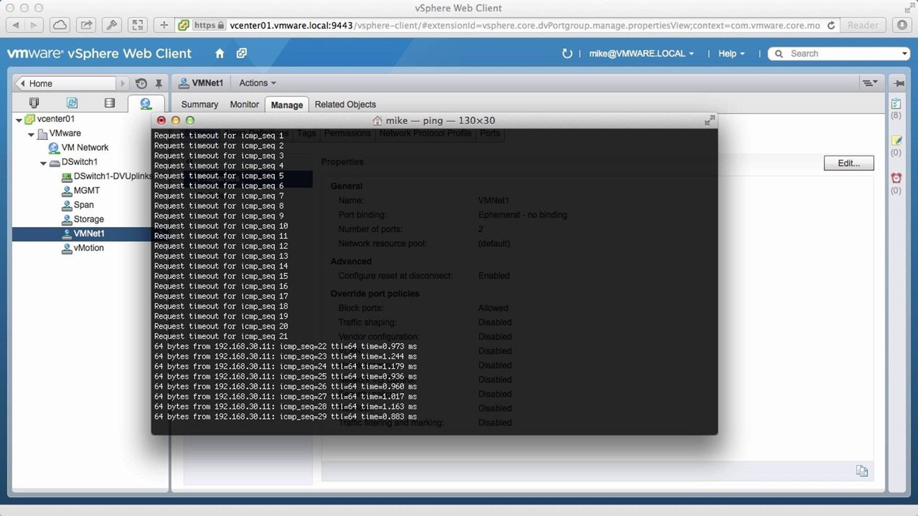
We now initiate a terminal session and attempt to ping web01. Notice that the pings are failing because we the traffic filter is in place.
Change the Action to [Allow] and click on [OK].
We switch back to the terminal session and see that the pings are now successful. To summarize, traffic filtering gives the ability to do create Access Control Lists at the Distributed Port Group level. This concludes the walkthrough on how to configure Traffic Filtering using the vSphere Distributed Switch. Select the next walkthrough of your choice using the navigation panel.
NetFlow

This walkthrough is designed to provide a step-by-step overview on how to configure NetFlow available with vSphere Distributed Switch. Use arrow keys to navigate through the screens.
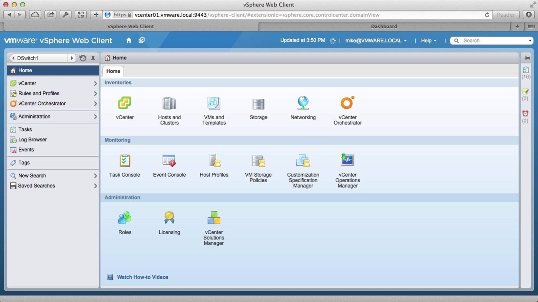
Begin by logging onto the vSphere Web Client and go to the [Networking] section.
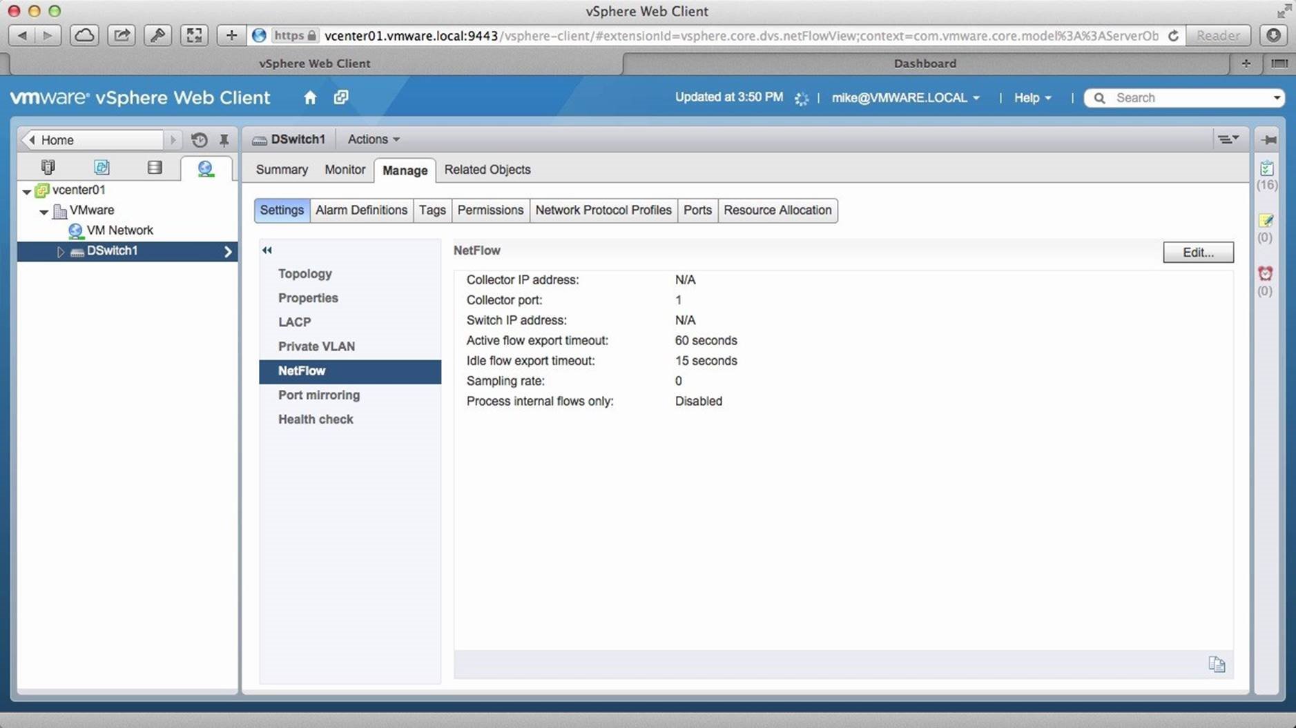
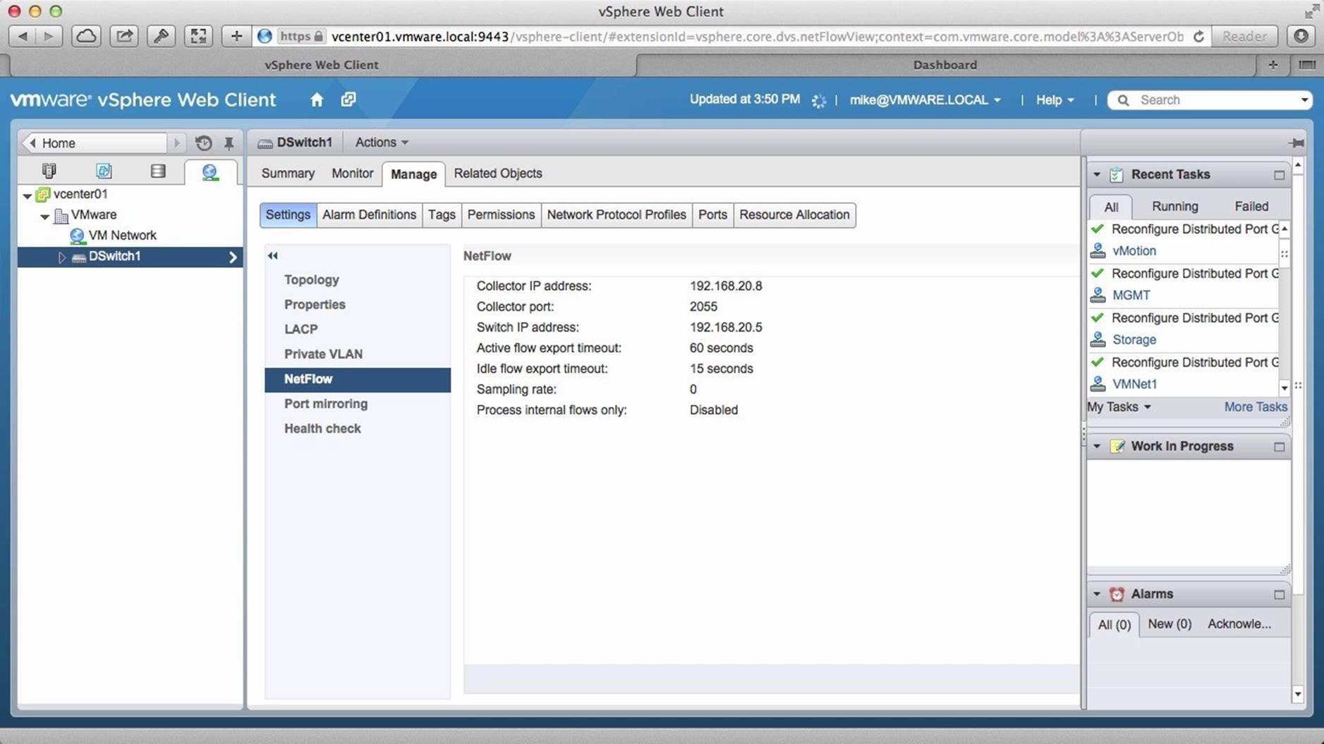
Select the [Distributed Switch] and go to the [Manage] tab. Select [NetFlow] and click on [Edit].
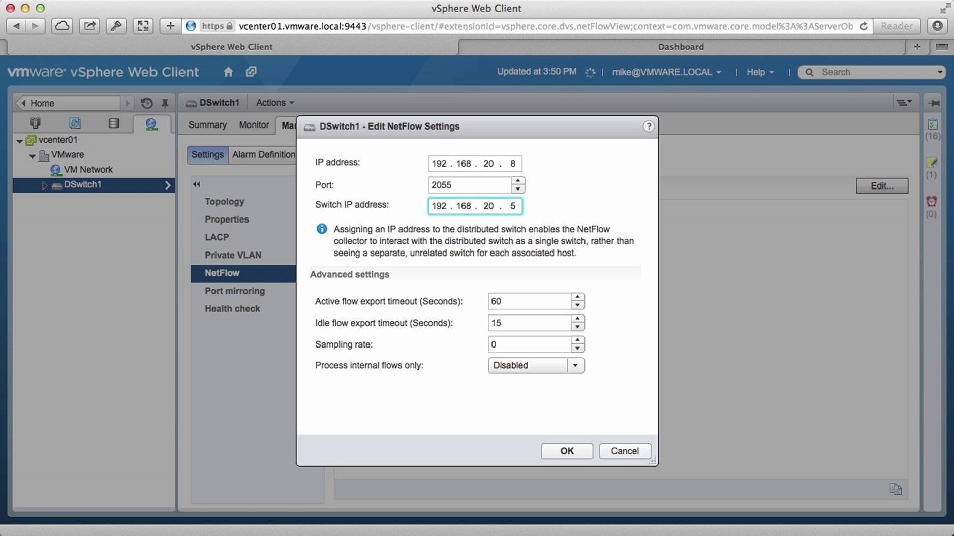
Enter the IP address of the NetFlow Collector, the port that it is listening on and then the IP address of the vSphere Distributed Switch. NetFlow collector will collect the data by tracking this IP address. Configure the remaining settings as required and click on [OK].
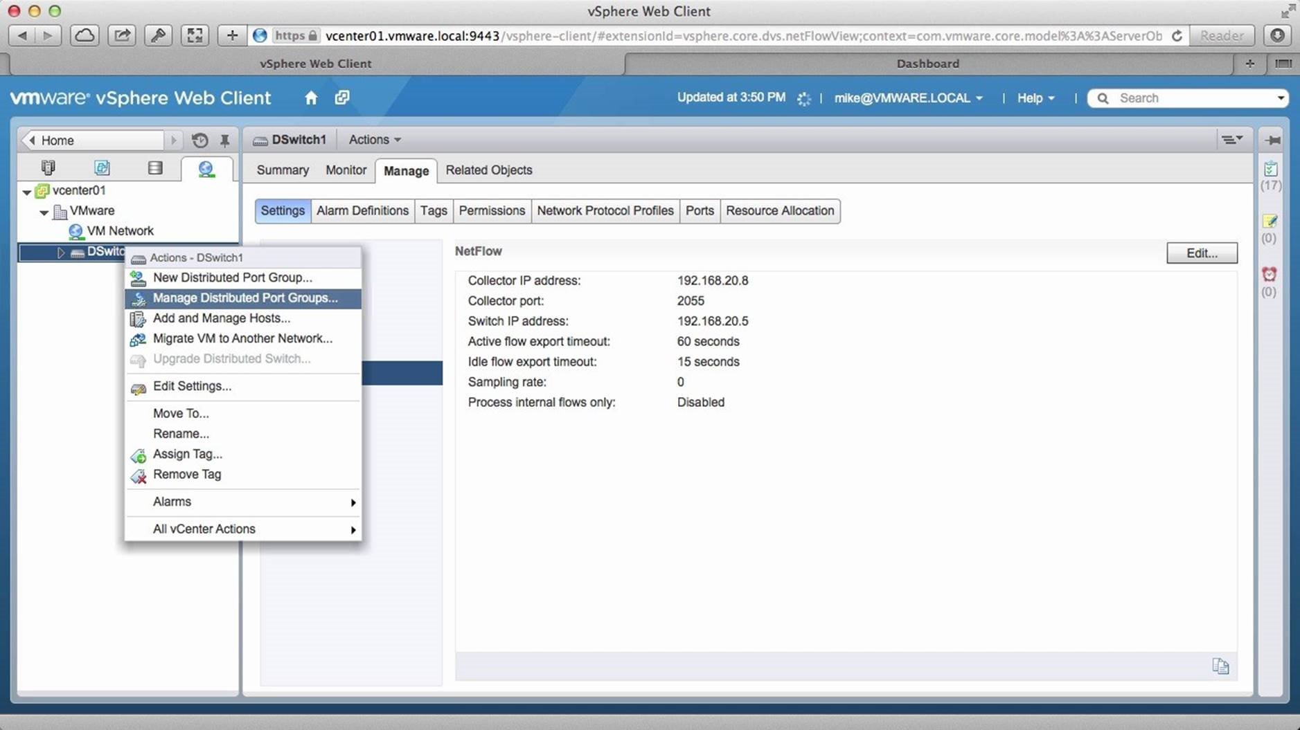
NetFlow is now configured on the switch. Next we have to enable NetFlow on the port groups that you want to collect the data from. To do this, right click on the [Distributed Switch] and click on [Manage Distributed Port Groups].
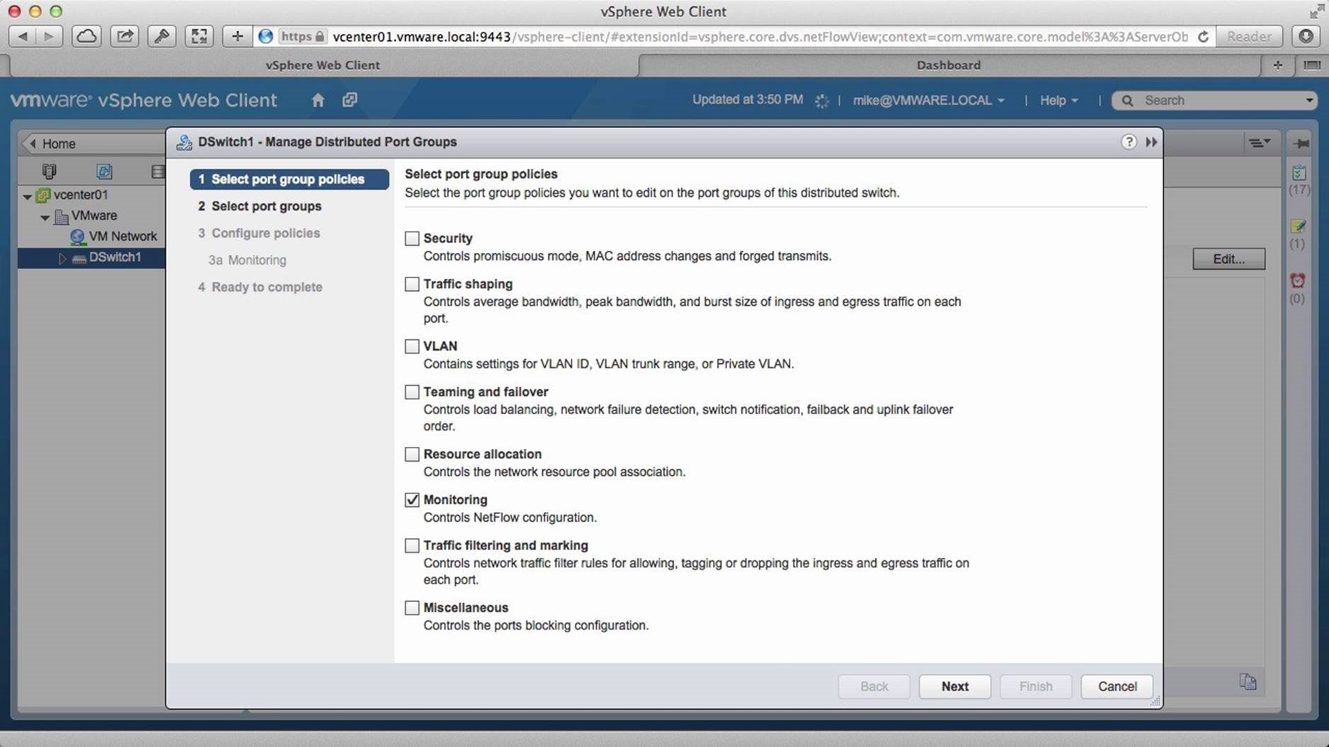
Select [Monitoring] and click on [Next].
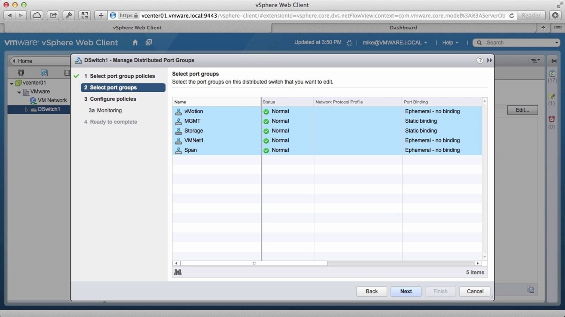
Select the port groups you want to enable NetFlow on and click on [Next].
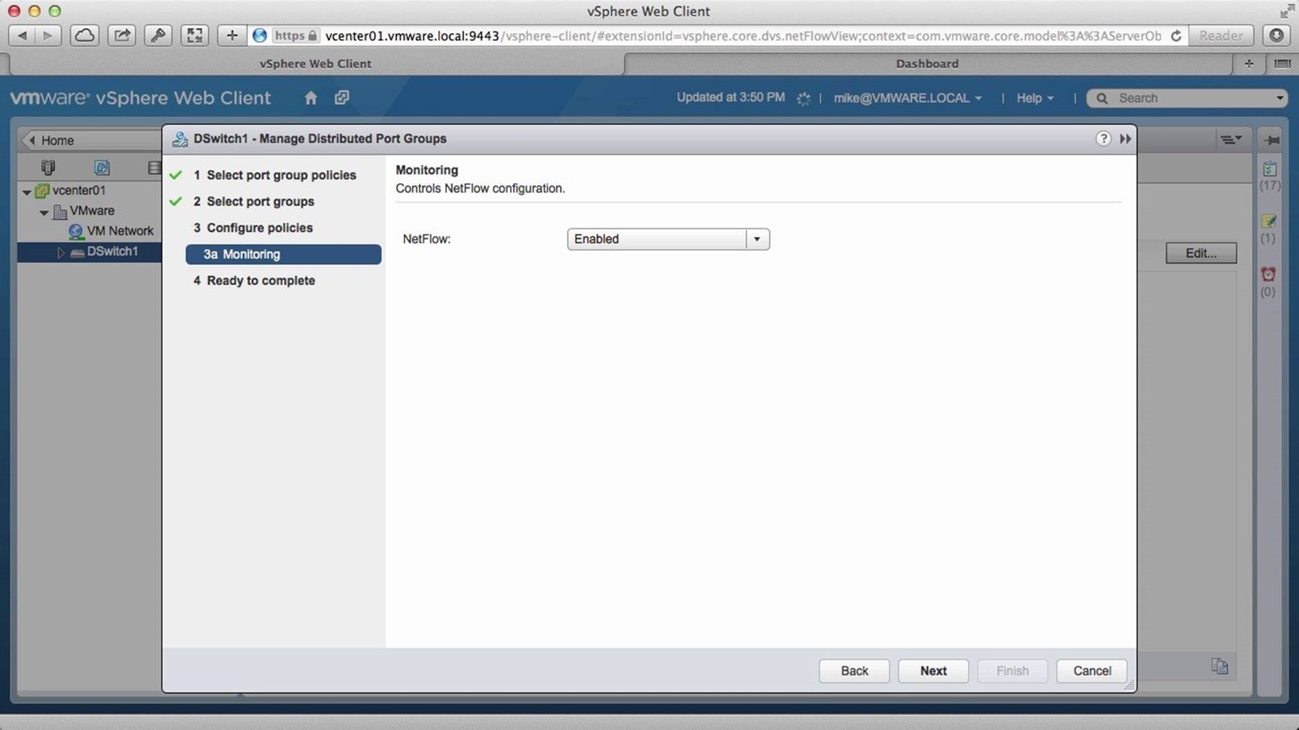
[Enable] NetFlow and click on [Next].
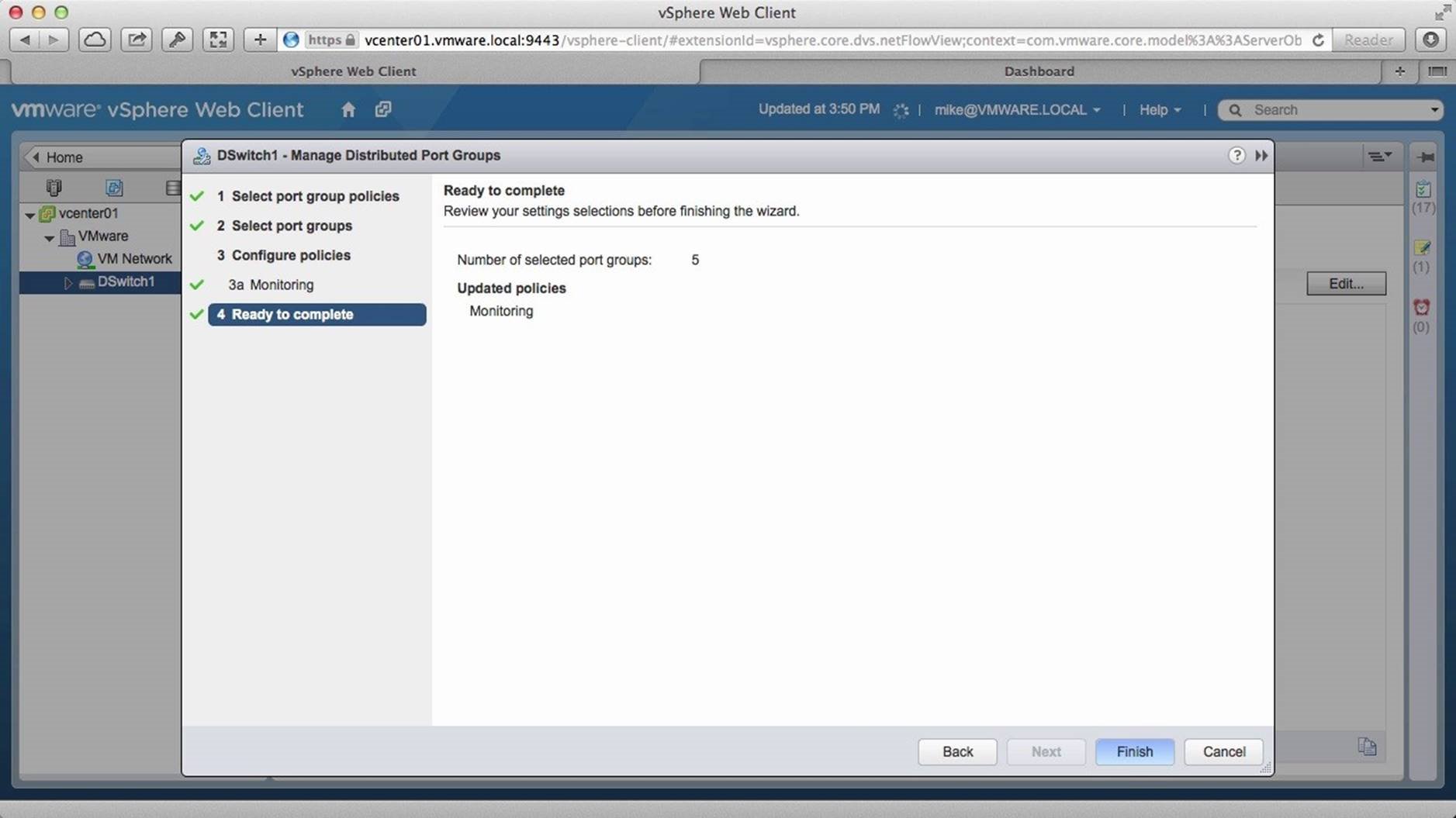
Review the settings and click on [Finish].
Monitor the progress on the recent tasks column. Once configuration has been completed, access a NetFlow collector dashboard to observe the changes.
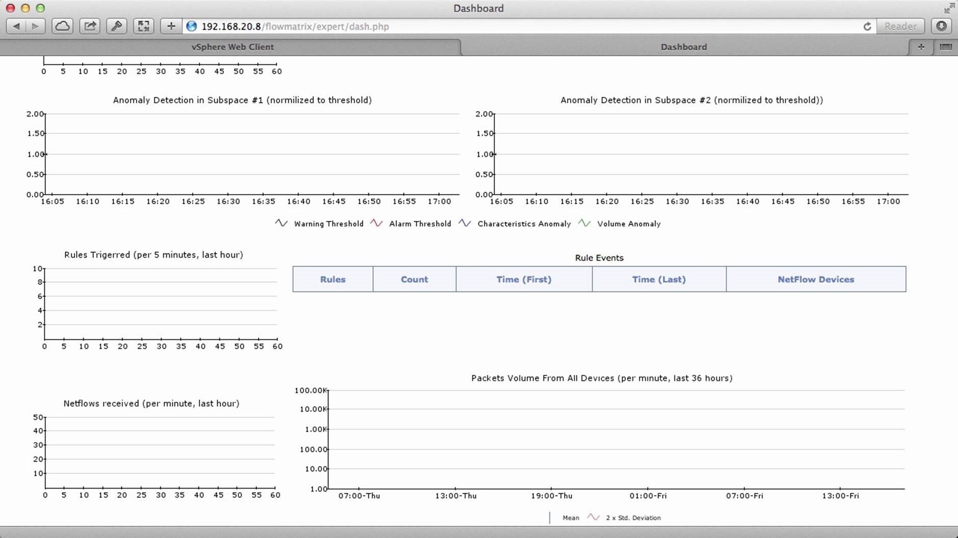
In this example we have a free NetFlow collector dashboard running. Notice that because NetFlow was only recently enabled there are no NetFlows being collected currently.
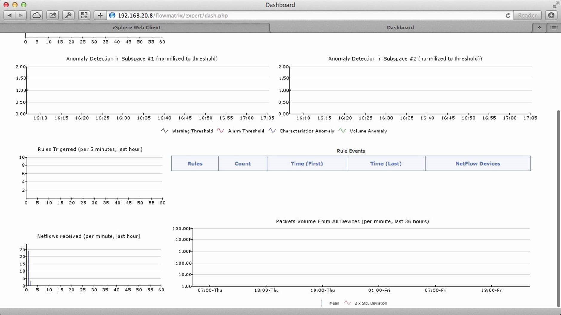
After a few minutes, we see that the collector is receiving the NetFlow data.
This concludes the walkthrough on how to configure the NetFlow feature in vSphere Distributed Switch. Select the next walkthrough of your choice using the navigation panel.
Configure Standard Switch
This walkthrough is designed to provide an overview of VMware vSphere Standard Switch and help you get started with vSphere Standard Switch. Use the arrow keys to navigate through the screens.
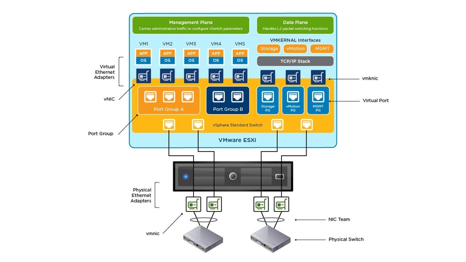
Before we look at how to configure a vSphere Standard Switch (vSwitch), let’s first understand what a vSwitch is and where it exists within a vSphere environment. Here is a sample vSphere environment where we see that the vSwitch is at the core of vSphere networking.
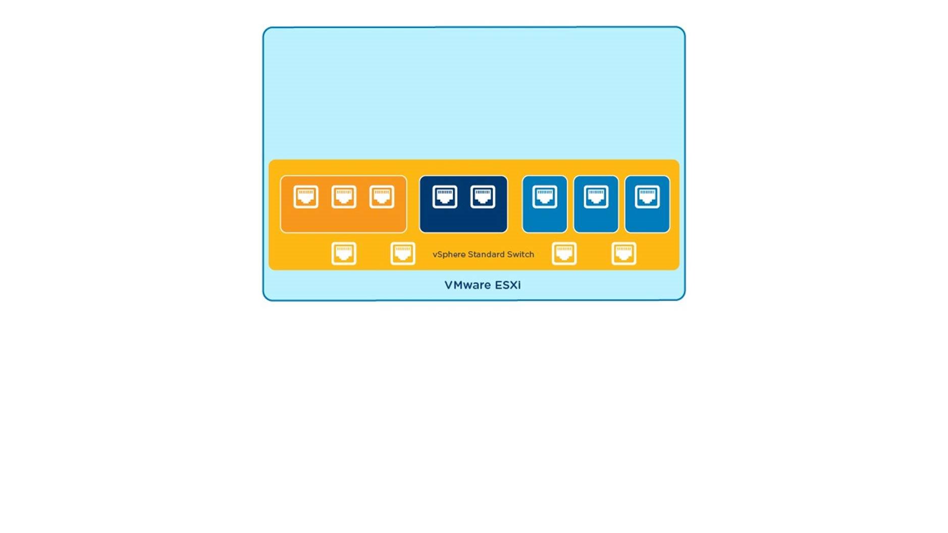
A vSwitch is a software construct within the VMware ESXi hypervisor that emulates a layer 2 Ethernet switch. A vSphere Standard Switch and its configuration is unique to the ESXi host on which it exists.
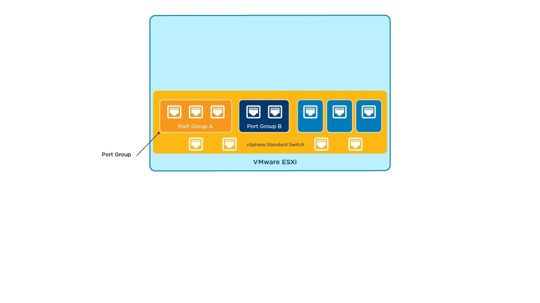
Each virtual switch has a preset number of virtual ports and one or more port groups. A port group is a logical collection of ports with the same settings or policies, such as a VLAN tag.
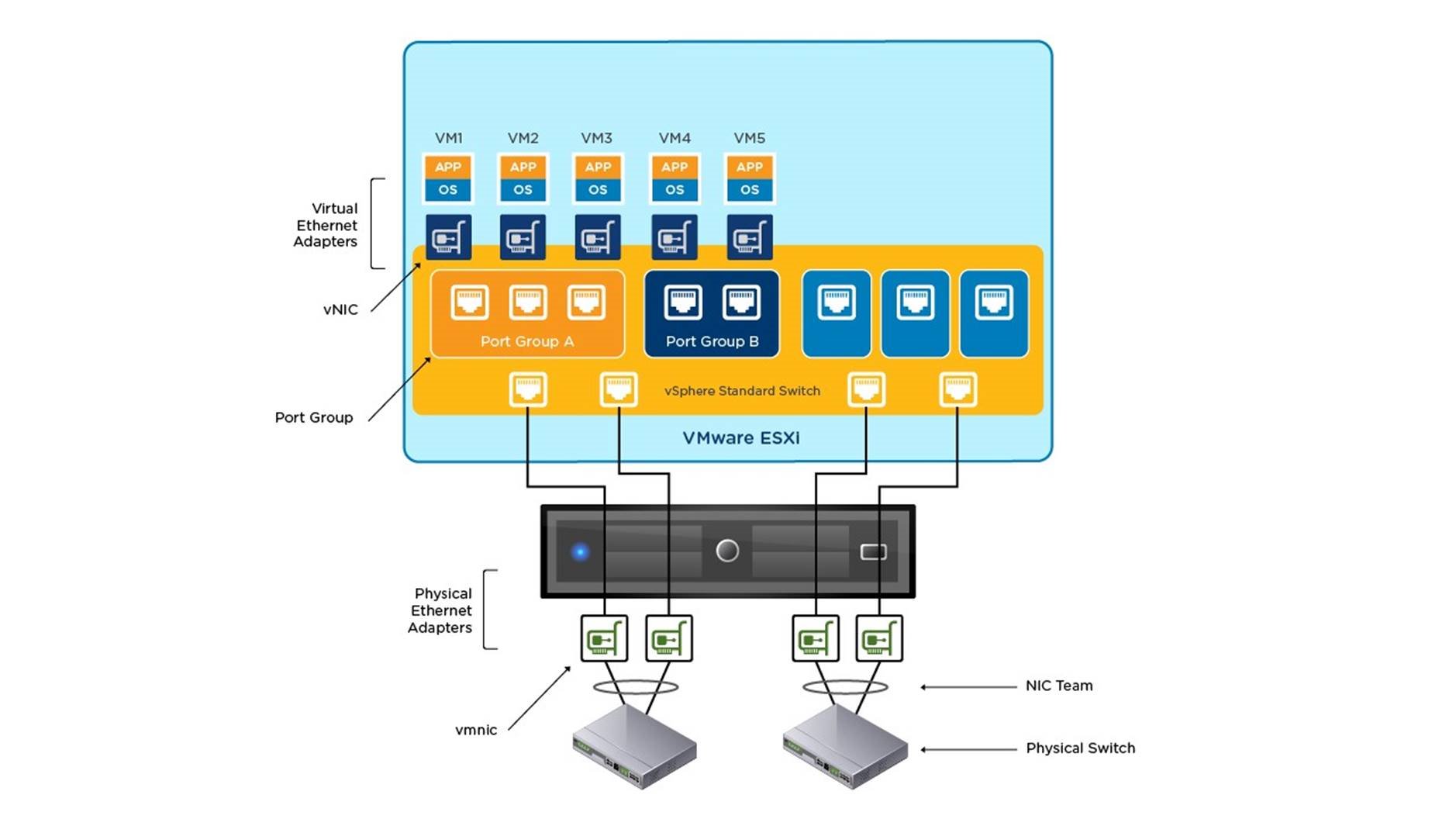
Virtual machines virtual NICs are logically connected to a virtual port in the same way that a physical NIC would be patched into a physical switch.
When two or more virtual machines are connected to the same virtual switch, network traffic between them is routed locally. When virtual machines are connected to a virtual switch, that in turn is connected to an uplink adapter (called a vmnic), each virtual machine can access the external network through that uplink.
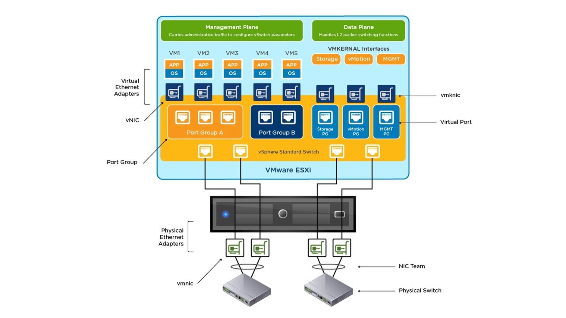
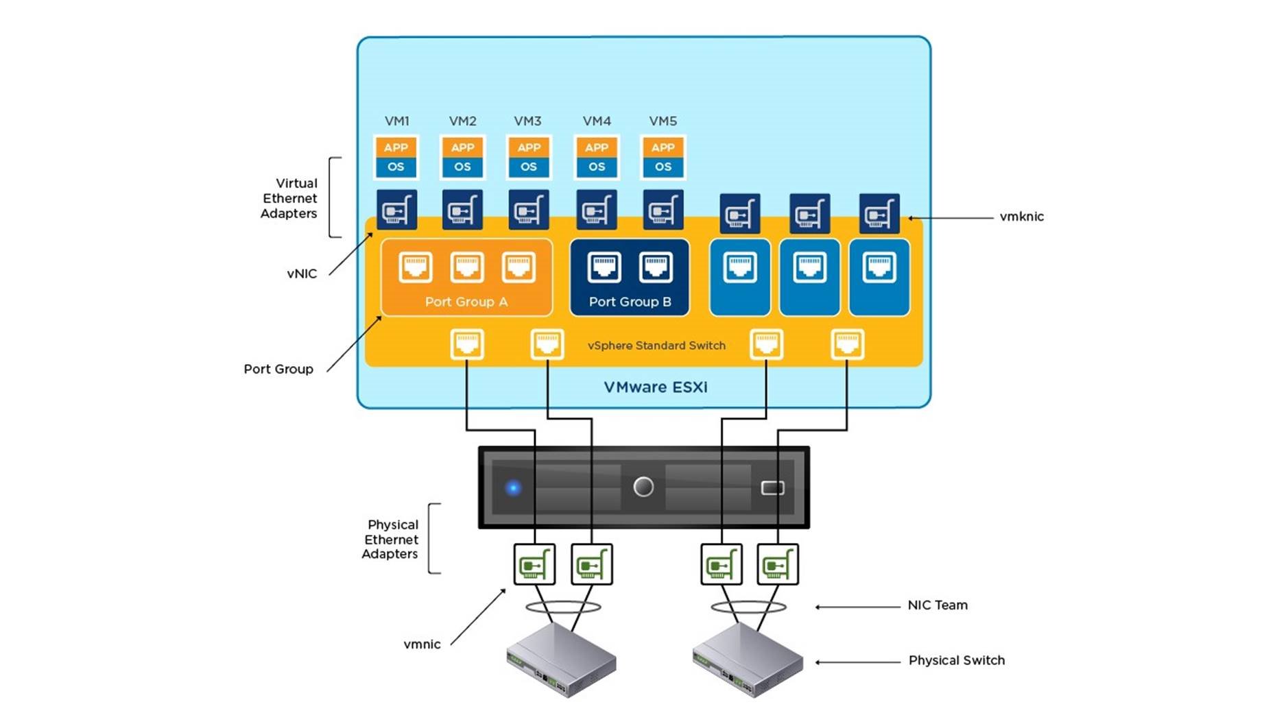
Virtual switches allow ESXi hosts to migrate virtual machines with VMware vMotion and to use IP storage through VMkernel network interfaces. Using vMotion, you can migrate running virtual machines with no downtime. IP storage refers to any form of storage that uses TCP/IP network communication as its foundation and includes iSCSI and NFS for ESXi. Because these storage types are network based, they can use the same VMkernel interface and port group.
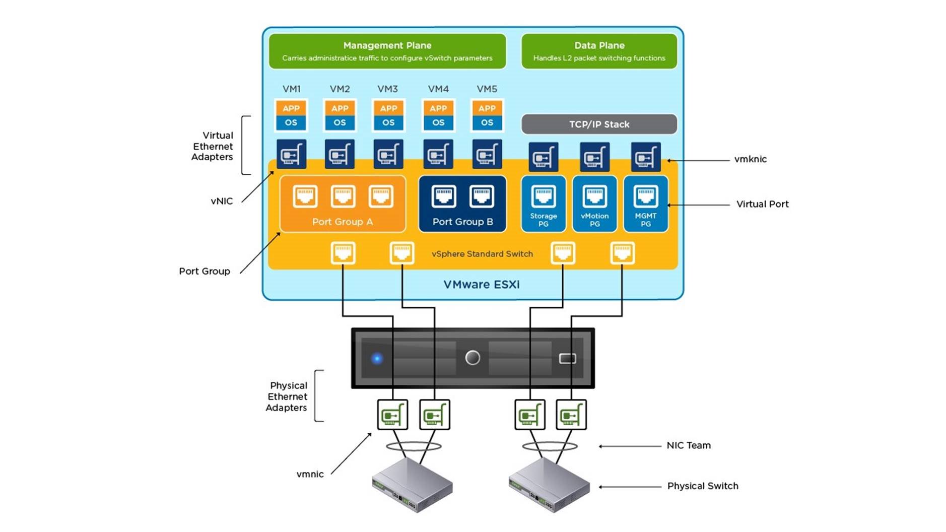
Network services provided by VMkernel (iSCSI, NFS, and vMotion), use a TCP/IP stack within the VMkernel. The VMkernel TCP/IP stack is also separate from the guest operating system’s network stack. These stacks access various networks by attaching to one or more port groups on one or more virtual switches.
Now that you are familiar with vSwitches, let’s look at how to configure vSphere Standard Switches. Begin by logging on to the vSphere Web Client.
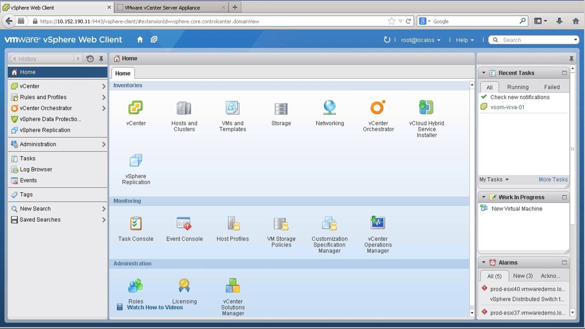
Navigate to Hosts and Clusters.
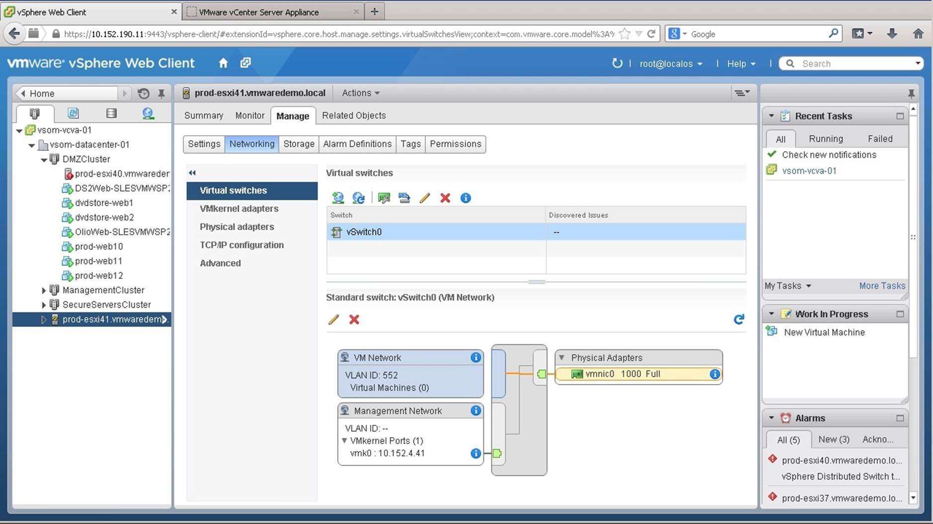
Select the [Host] for which you want to configure vSwitch. Go to the [Manage] tab and then under [Networking], select [Virtual Switches]. Notice that a default switch named vSwitch0 already exists under virtual switches. Let us first see how to edit the settings of a vSwitch. Select [vSwitch0] and click on the Manage Physical Adapters [Icon].
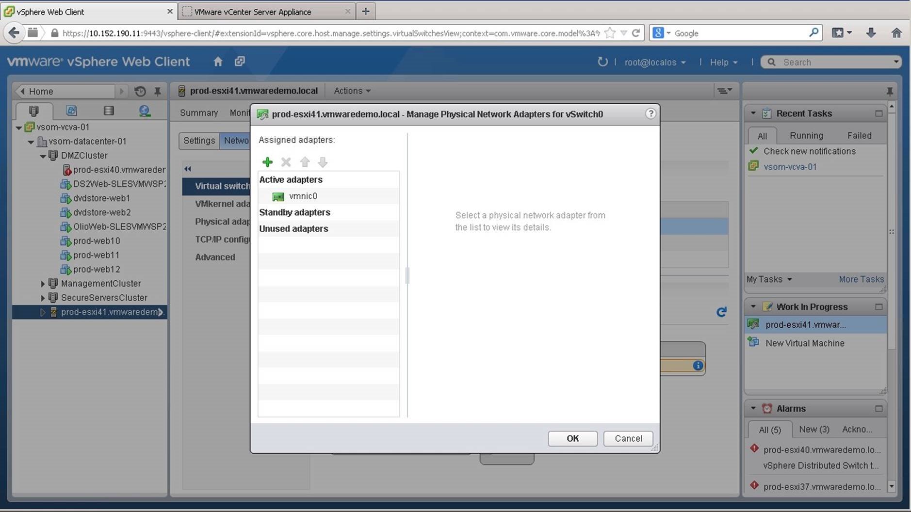
Notice that a single uplink named vmnic0 is connected to the virtual switch. Let us add a second uplink. Click on the add [+] icon.
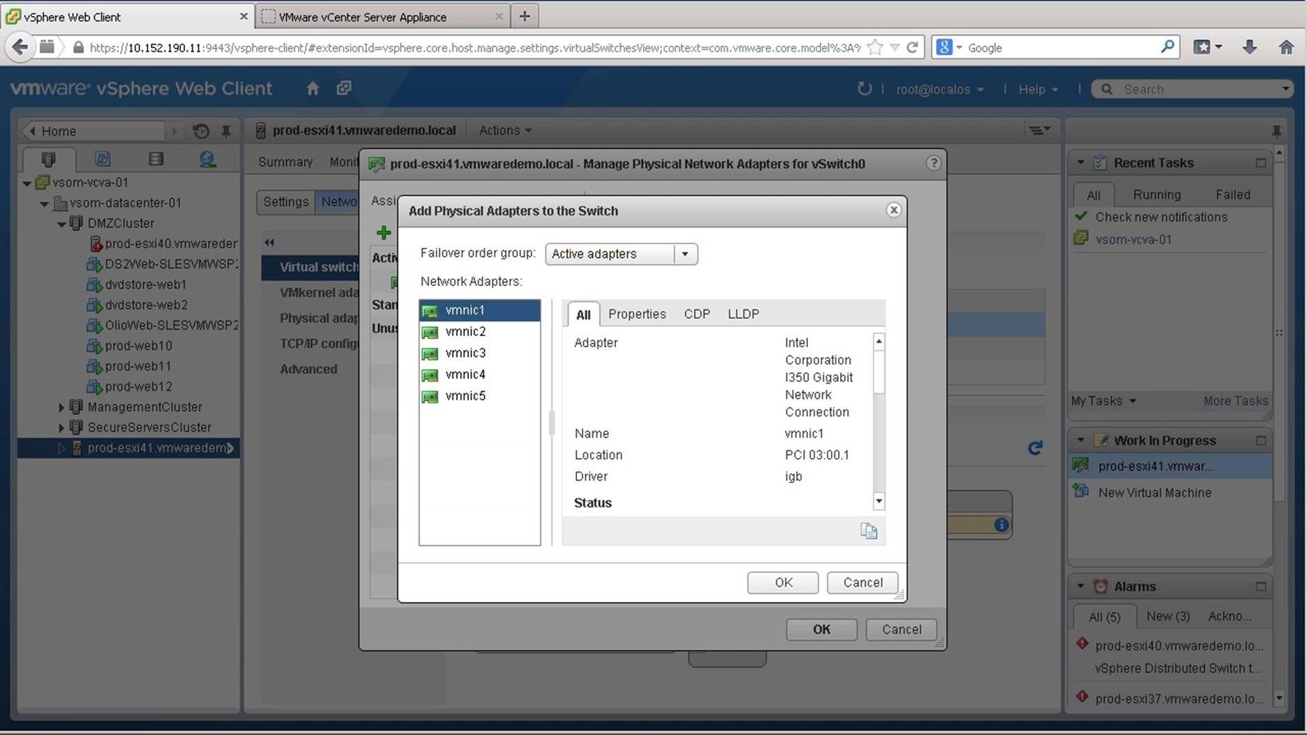
Select another uplink on the ESXi host and click on [OK]. In this example, we select [vmnic1].
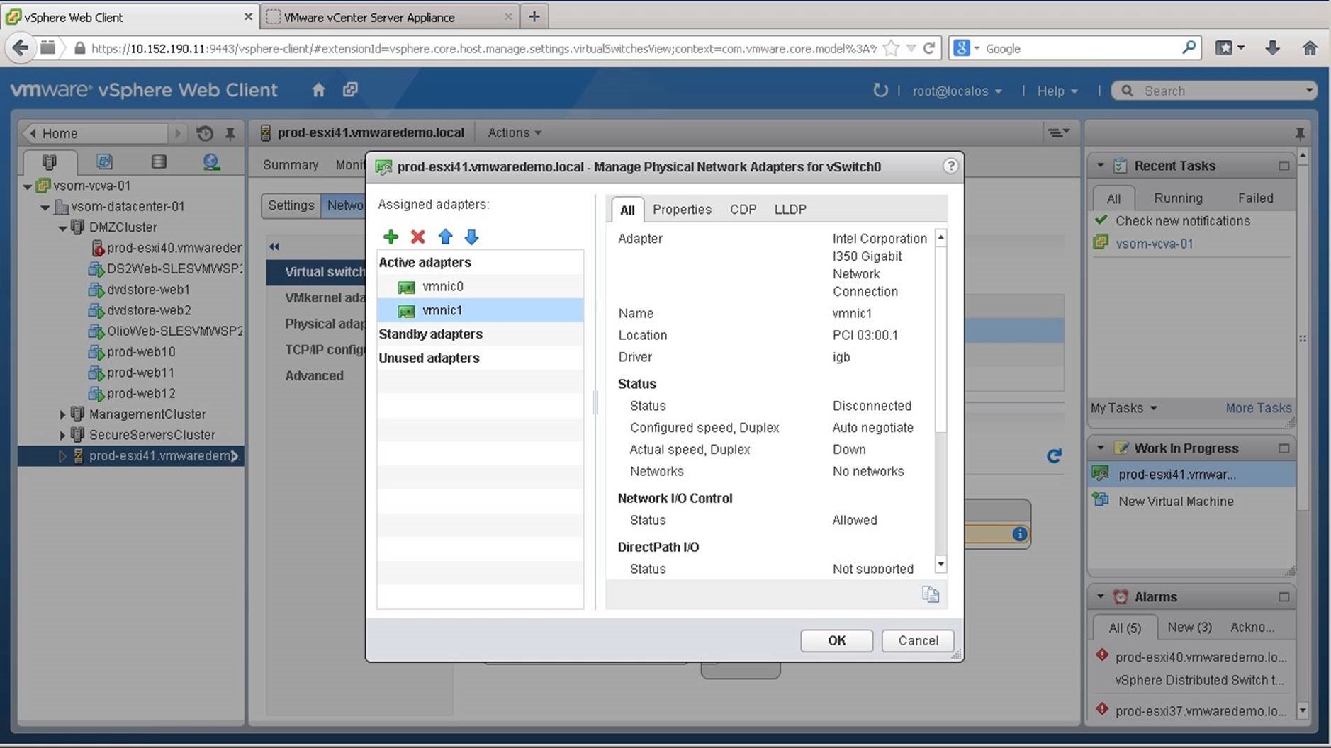
We choose to keep both the uplinks active and click on [OK]. Note: Each adapter should be connected to a separate physical switch to ensure high availability. Each physical switch port should be configured identically.
Identical settings should include trunk ports with access to VLANs you need to use. It is also recommended to enable PortFast or disable STP on the switch ports connected to vSwitch uplinks.
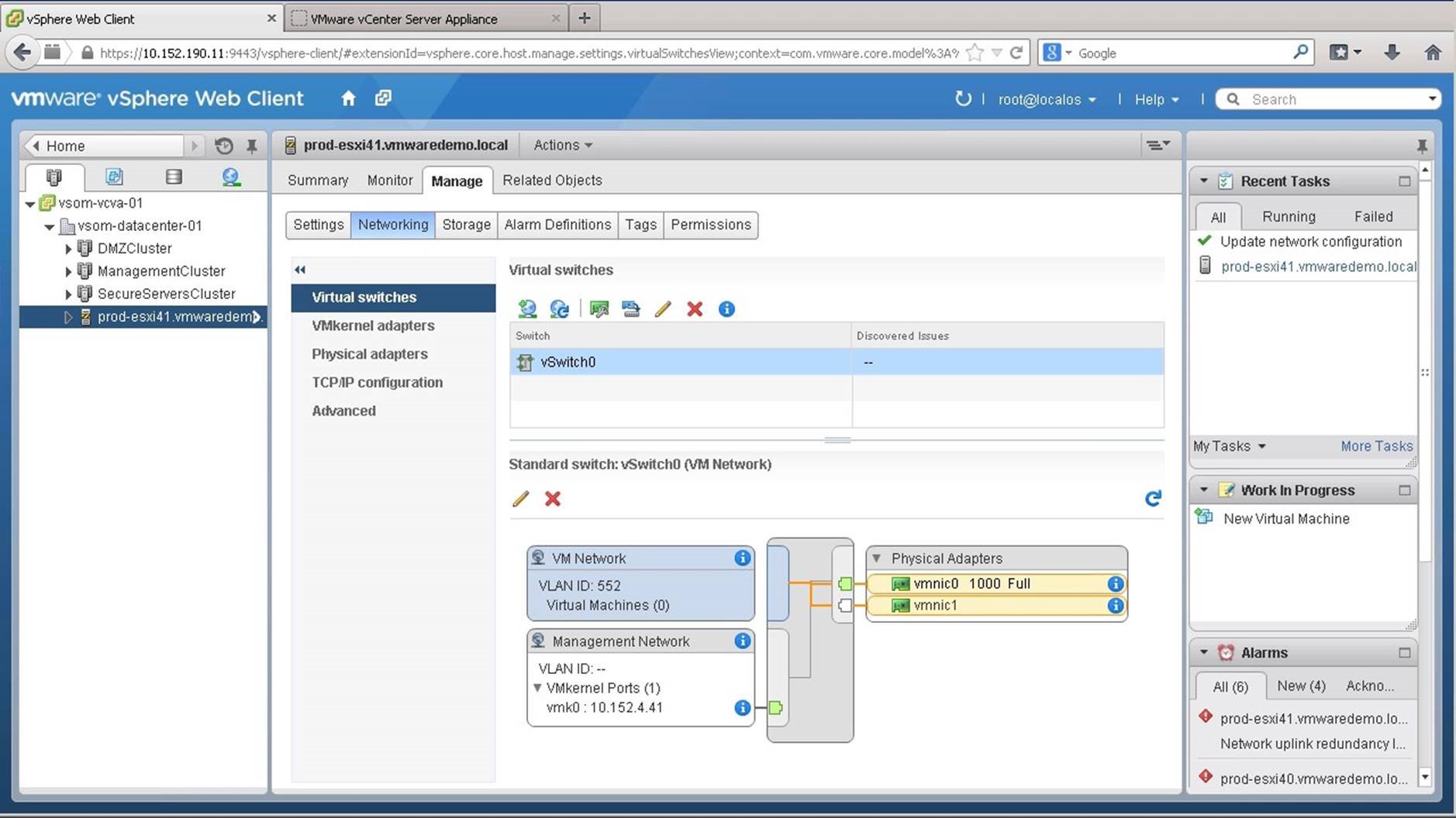
We will now create a new vSwitch to be used by vMotion, iSCSI and VMNetwork for other VLANs in our environment. Click on the [Add Host Networking] button.
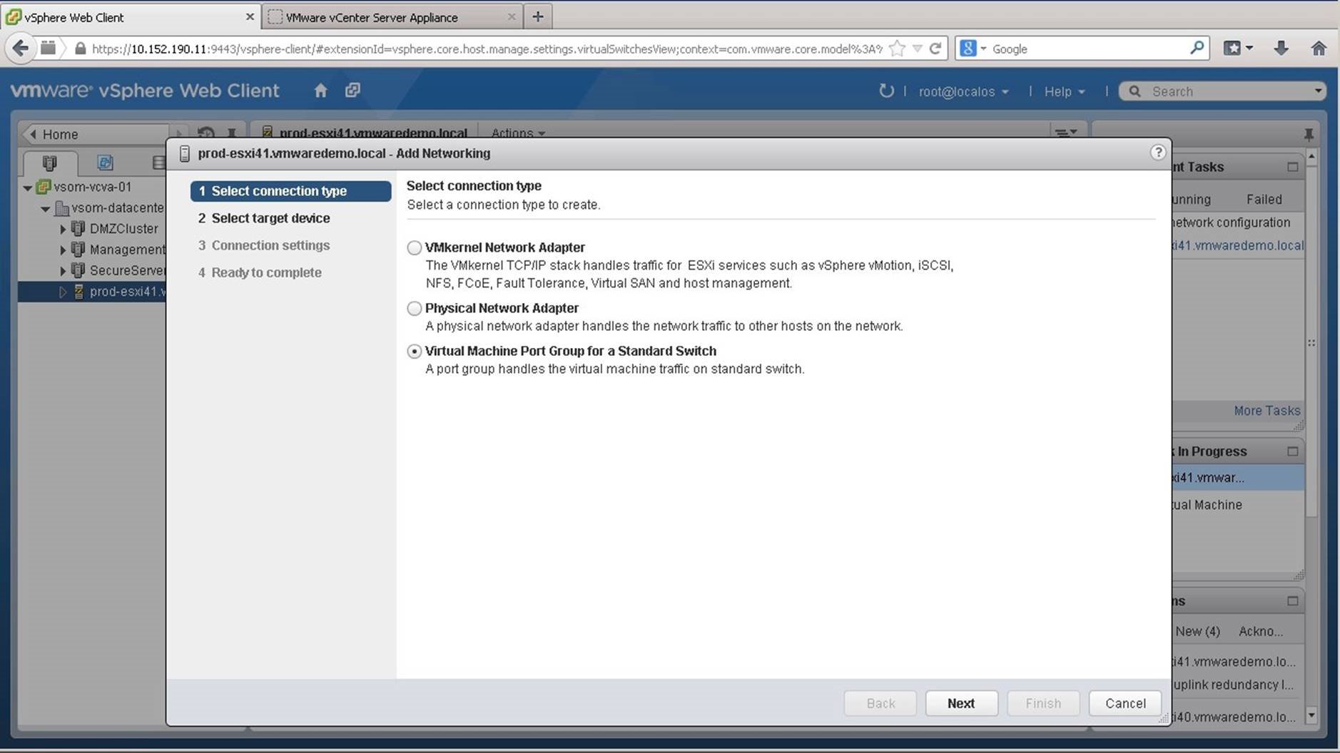
Choose the type of connection you wish to create. We select [Virtual Machine Port Group for a Standard Switch] and click on [Next].
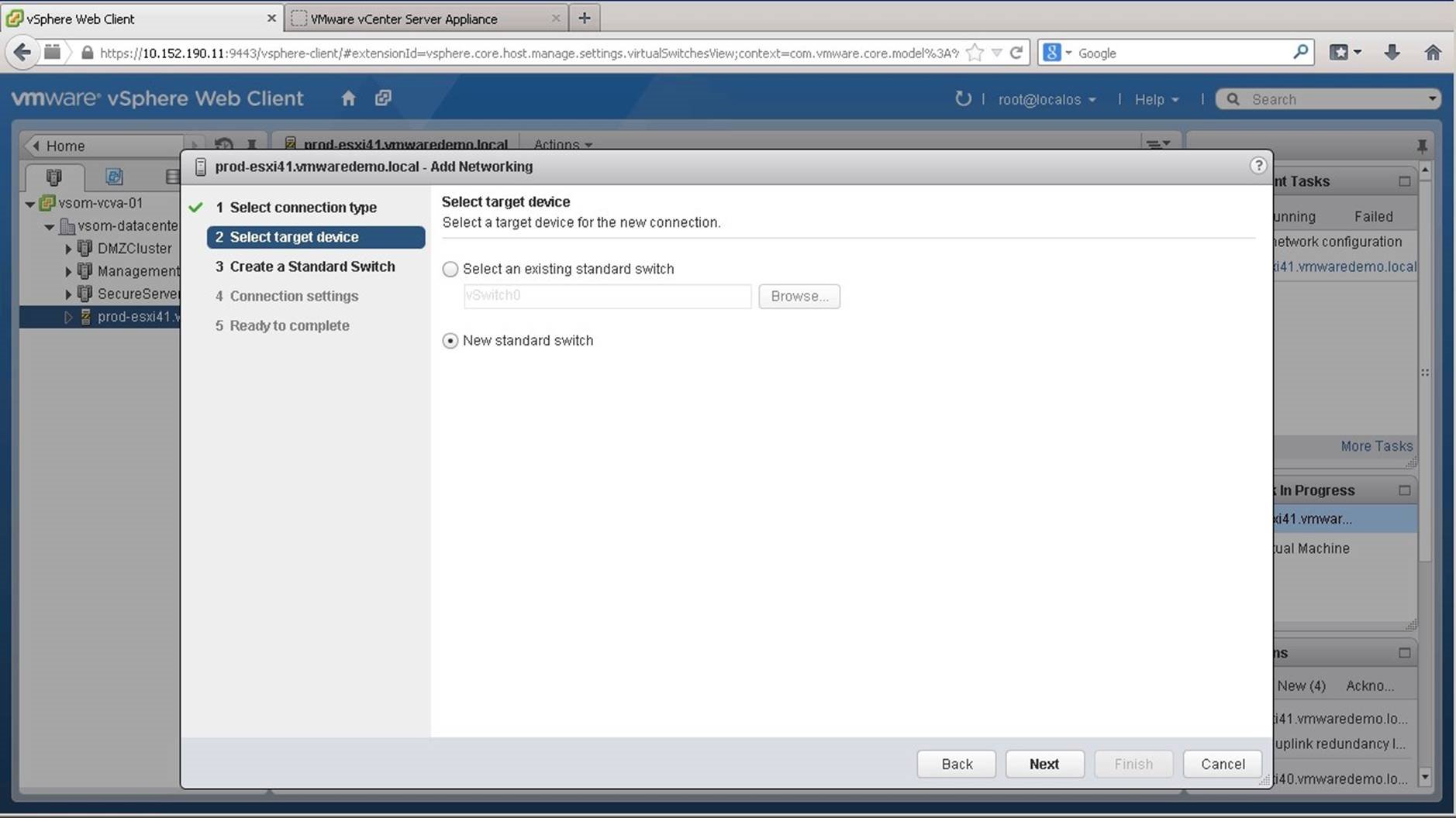
Select the target device for the connection. You can either retain the default selection on choose to create a new standard switch as we do in this example. Click on [Next].
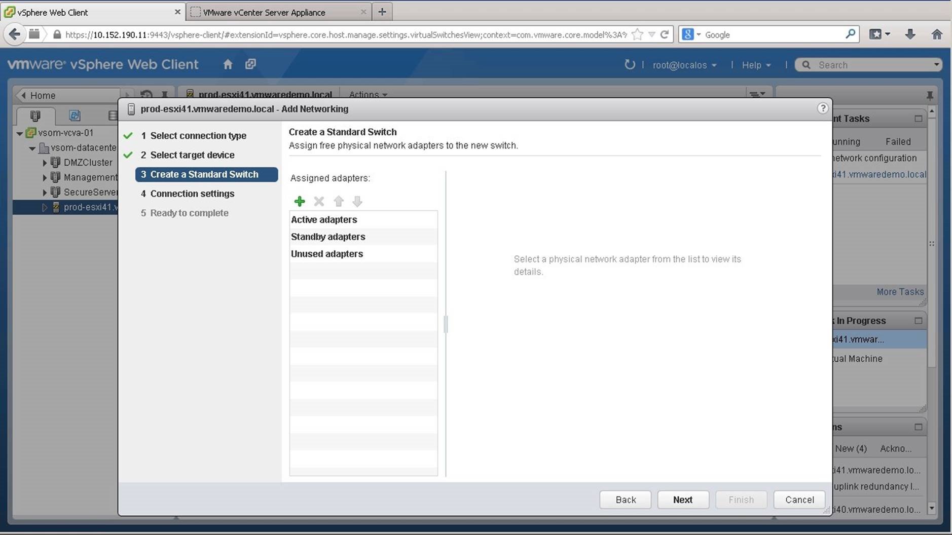
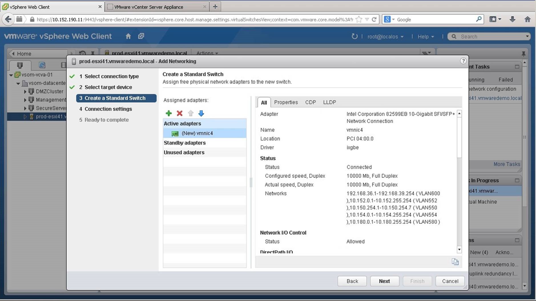
Next we need to assign physical network adapters as uplink ports on the switch. Click on the add [+] icon.
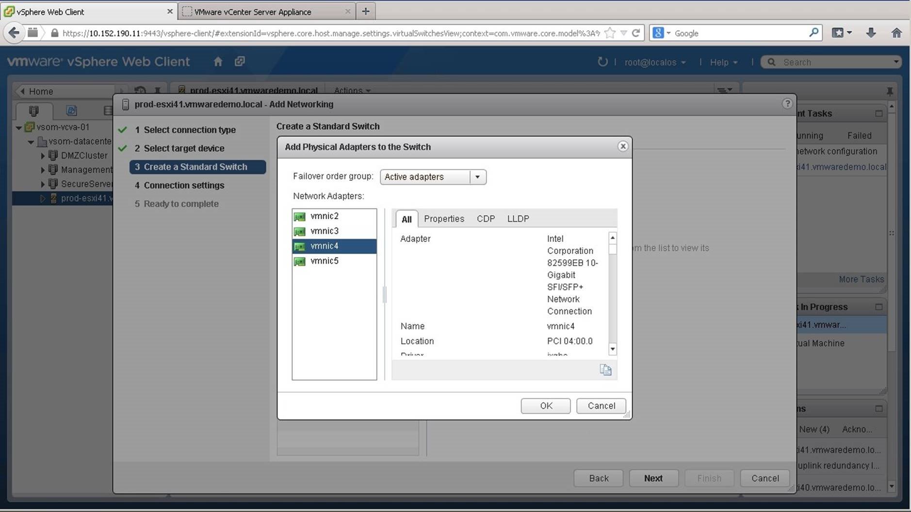
Select the uplink and click on [OK].
We click on the add [+] icon once again.
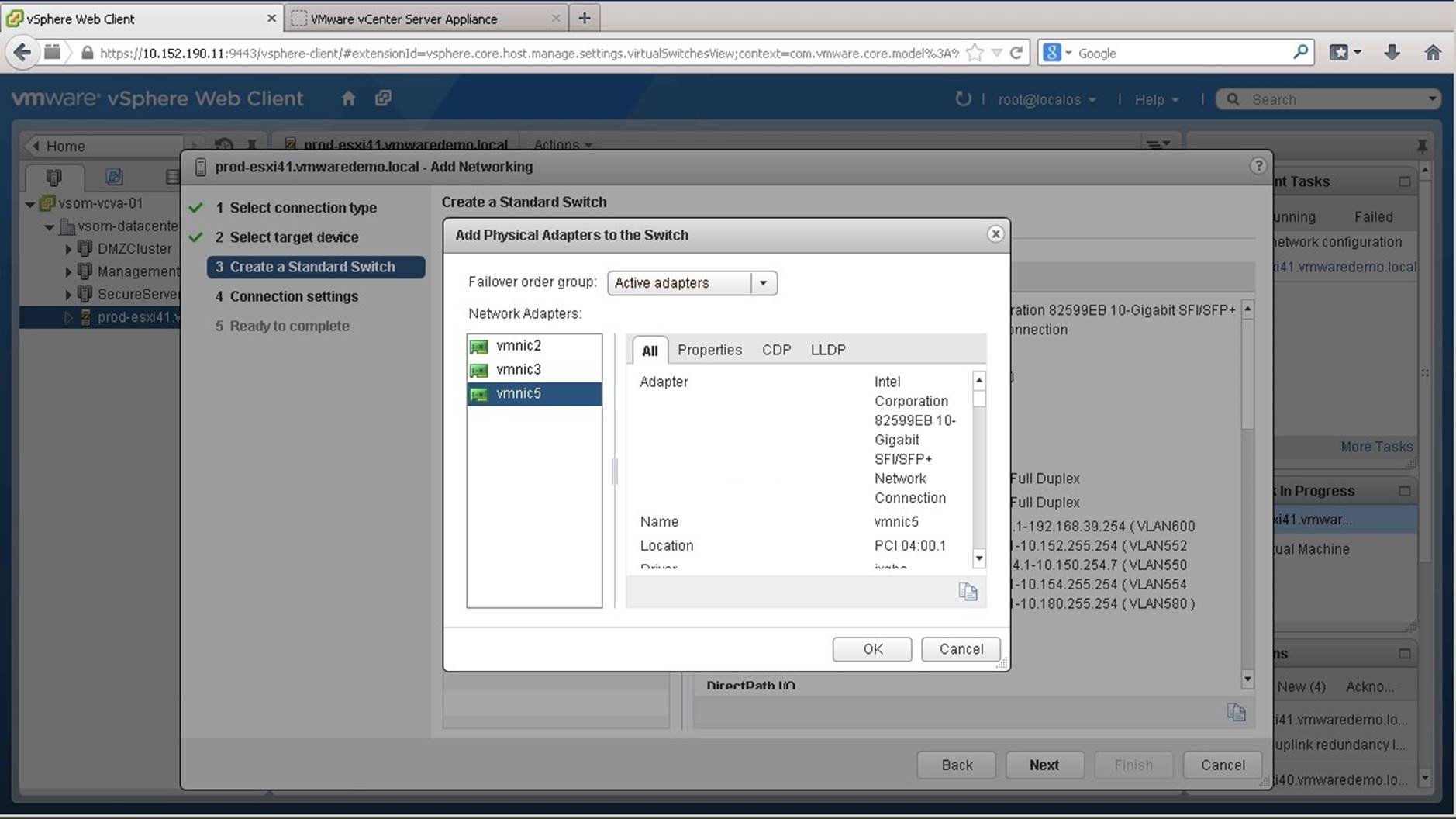
Select [vmnic5] and click on [OK]. Here vmnic4 and vmnic5 are connected to separate switches.
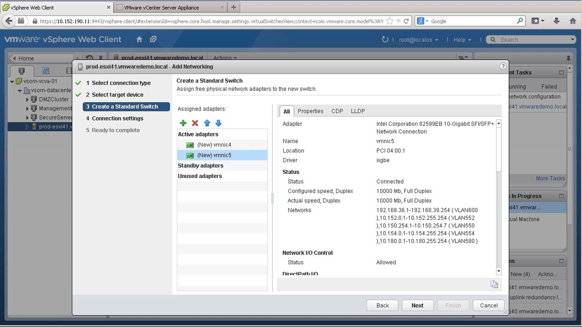
Click on [Next].
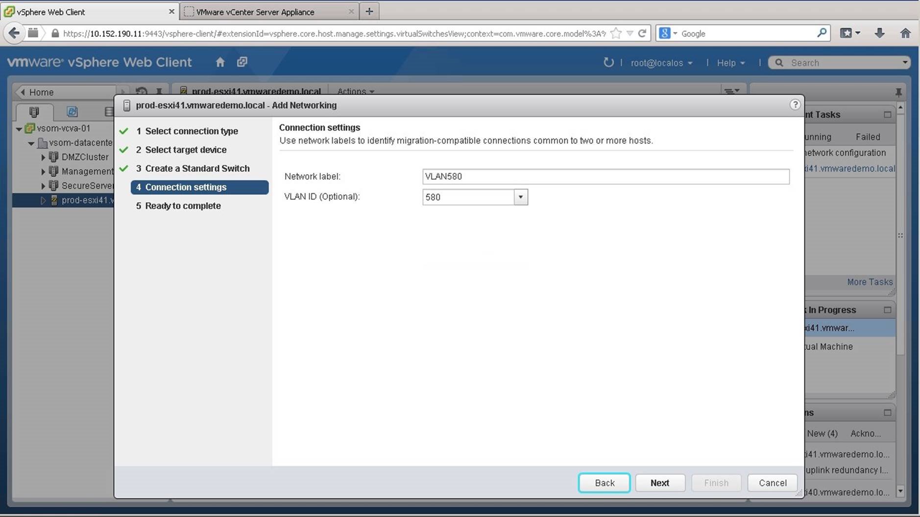
Assign a name to the network and click on [Next]. You also have the option to assign a VLAN. We select VLAN 580 for this port group.
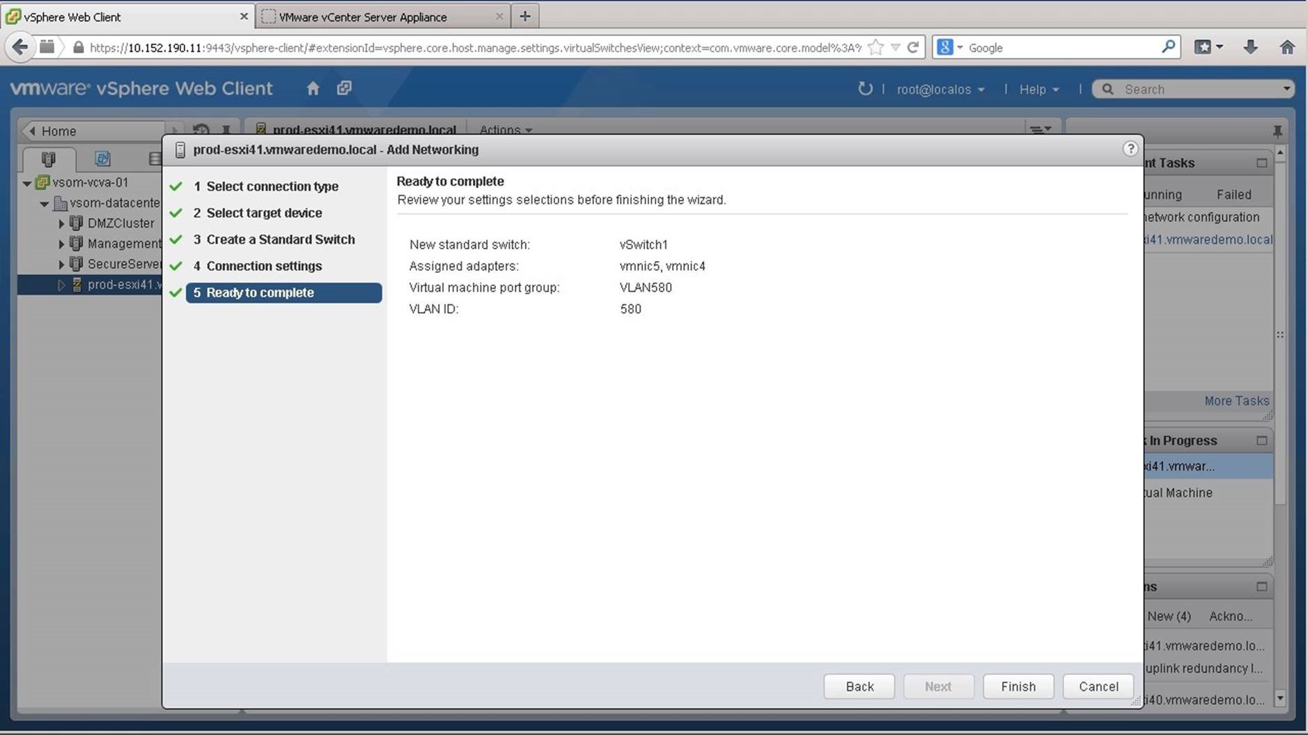
Review the settings and click on [Finish].
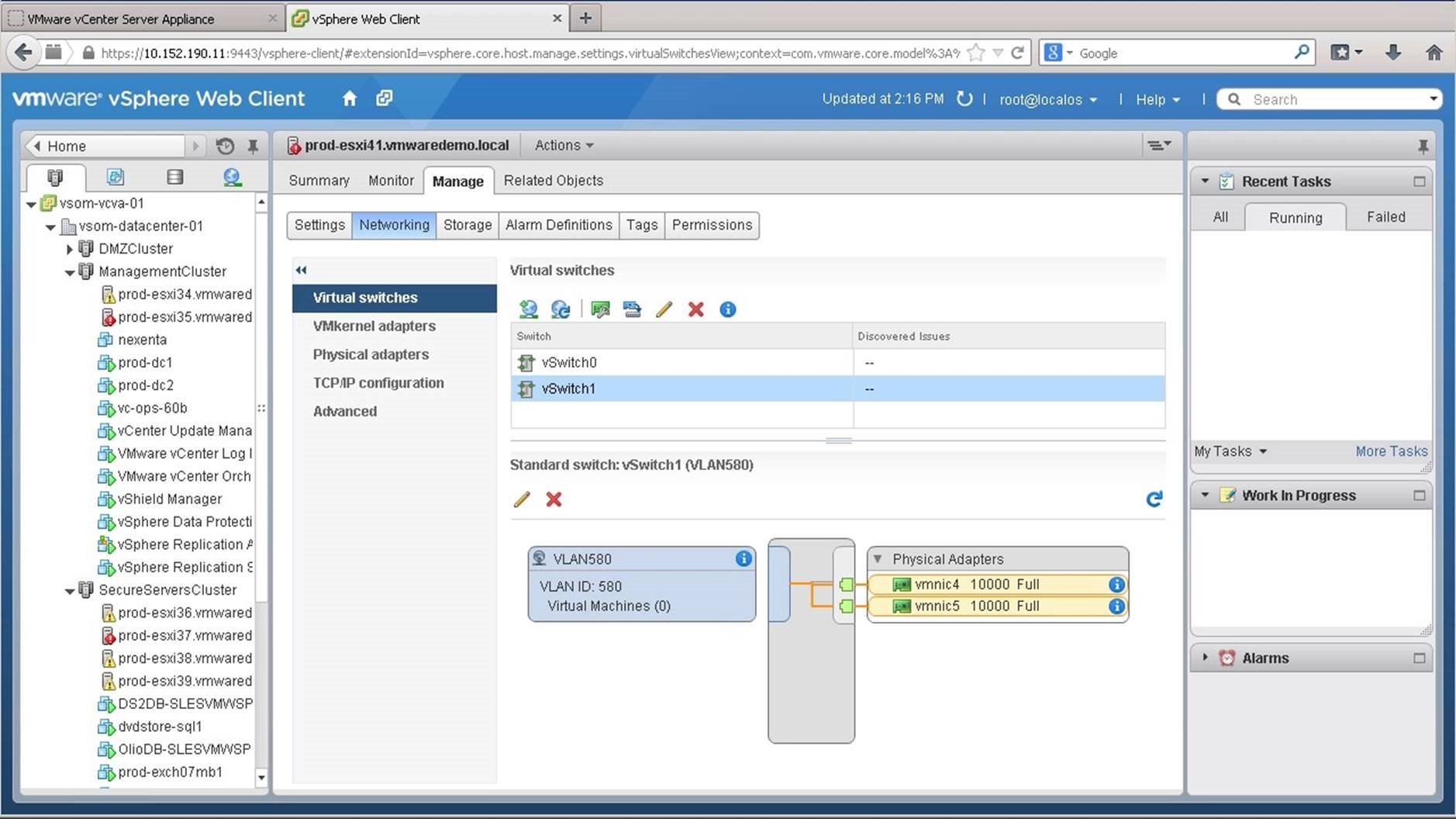
The new virtual switch, vSwitch1 has been created. Notice that the VLAN port group 580 and physical adapters vmnic4 and vmnic5 as uplinks are attached to the switch. Let us now add a new VMKernel Network Adapter for vMotion.
Click on the [Add Host Networking] icon.
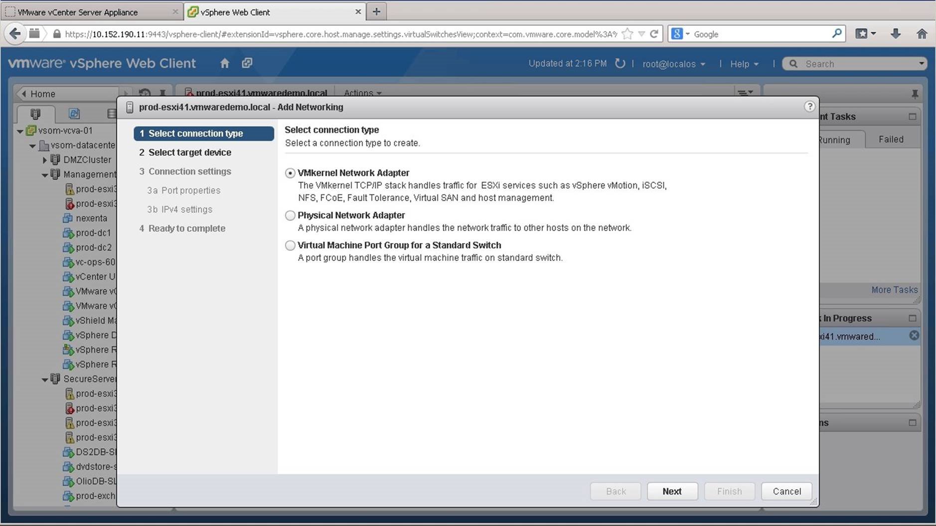
Select [Vmkernel Network Adapter] and click on [Next].
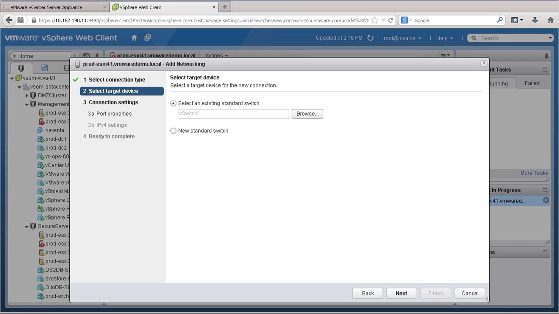
Select the standard switch. We retain the default to use vSwitch1 from the existing standard switches and click on [Next].
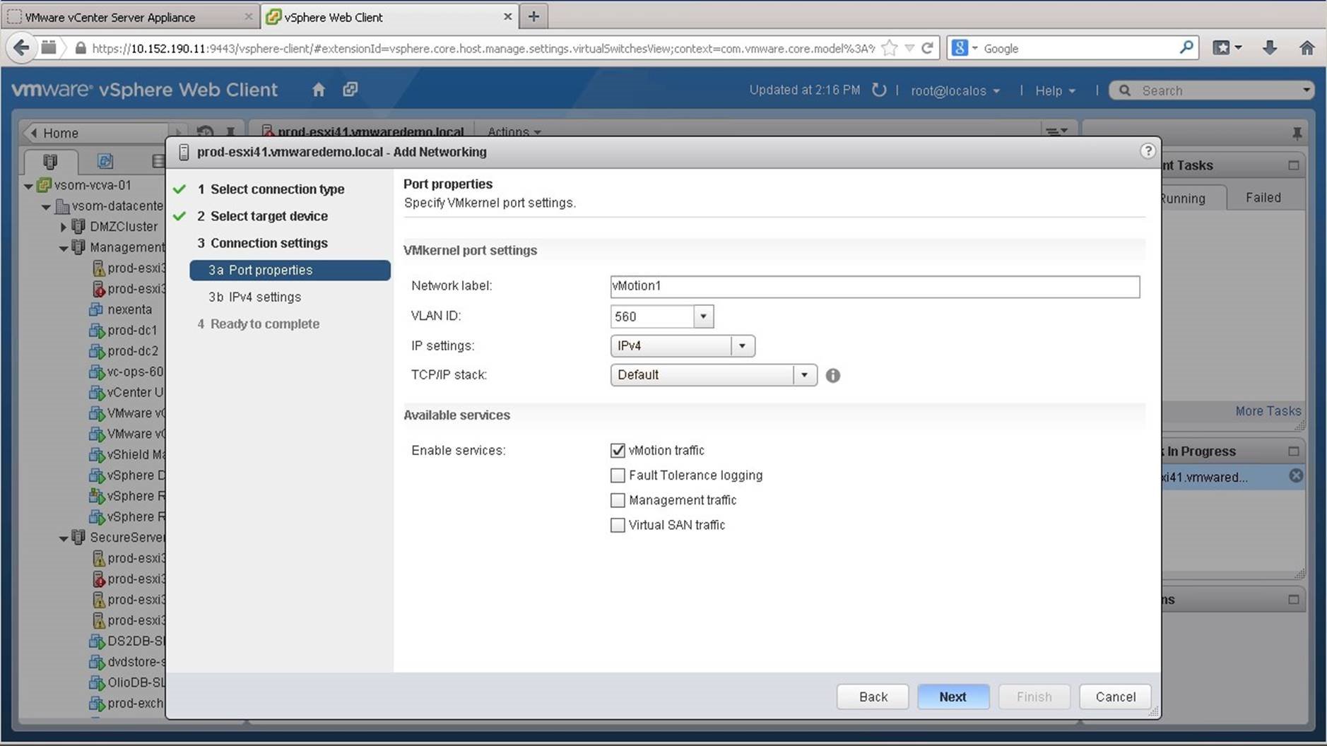
Assign the network label. We use vMotion1, select the VLAN ID and retain the IP settings to use IPv4 with the default TCP/IP stack. Enable vMotion Traffic and click on [Next].
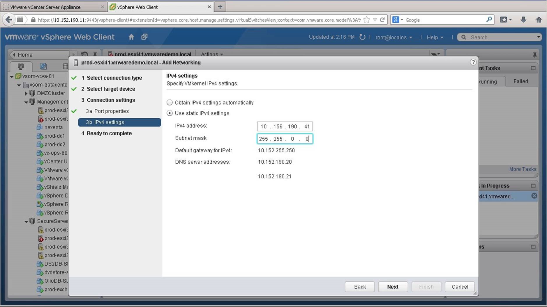
Specify if you want to obtain the IPv4 settings automatically or set the details manually. We configure the IP settings manually and click on [Next].
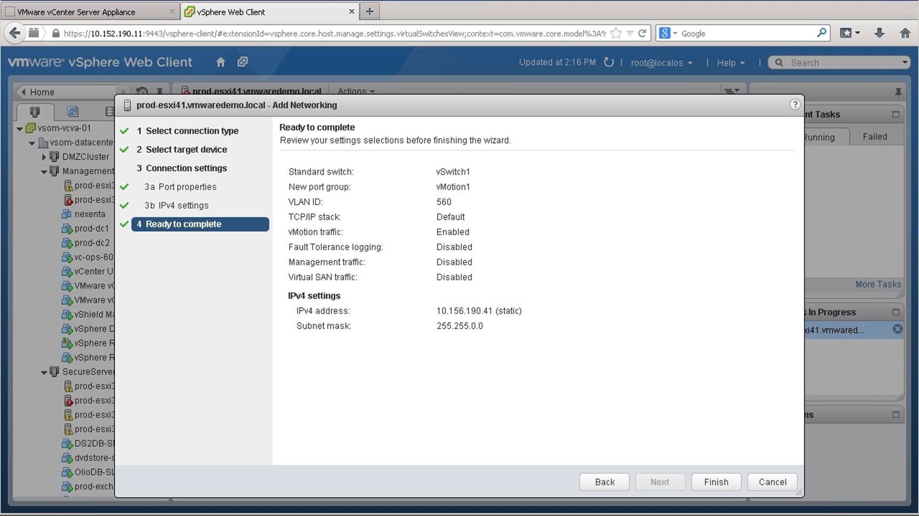
Review the settings and click on [Finish].
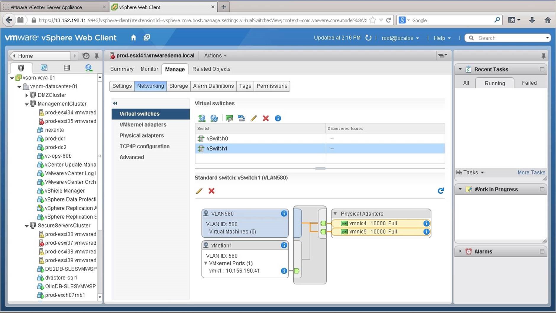
vSwitch1 now has a vMotion VMkernel port attached to the VLAN ID 560. The host is now ready to use vMotion and migrate virtual machines between itself and other hosts in the environment. Repeat the same process for other VM port groups as required. This concludes the walkthrough on how to get started with vSphere Standard Switch. Select the next waklthrough of your choice using the navigation panel.