
Microsoft Exchange 2013 on VMware vSAN
Executive Summary
This section covers the Business Case, Solution Overview and Key Results of the Microsoft Exchange 2013 on VMware vSAN document.
Business Case
Since the inception of email, Microsoft Exchange has evolved from a basic email application to a corporate-wide communication standard for most enterprises. During this evolution, Microsoft Exchange has also migrated from stand-alone servers to shared infrastructure with the goal of reducing costs and increasing availability.
Microsoft Exchange Server 2013 brings new technologies and features that are superior to that of legacy versions of Exchange. The architectural enhancements and implementation options, such as cloud extensions, are inviting features that make both existing and potential Exchange customers want to deploy Exchange 2013. This version of Exchange further solidifies its dominance in data centers and remains the premier corporate communication platform.
Adding VMware vSAN™ to the Exchange 2013 architecture aims at furthering the evolution by providing highly scalable, reliable, and high performance storage using cost-effective hardware, specifically directly attached disks in VMware ESXi™ hosts. vSAN embodies a new storage management paradigm that automates or eliminates many of the complex management workflows that exist in traditional storage systems today. vSAN enables IT administrators to easily deploy and administer Microsoft Exchange 2013 on VMware vSphere while still maintaining high availability and reducing costs using a shared infrastructure hosted on ESXi.
Solution Overview
In this solution, we validate that vSAN can support a mixed mailbox size configuration under load and stress using a highly available cluster architecture. We cover best practices and optimal configurations for Exchange 2013 on vSAN.
Key Results
The following highlights validate that vSAN is an enterprise-class storage suitable for Microsoft Exchange:
- Predictable storage I/O performance for Exchange on vSAN.
- Simple design that eliminates maintenance complexity of traditional SAN nor additional Windows utility software to deploy storage for Microsoft Exchange.
- Disaster recovery and data protection planning demonstrating site resiliency and mailbox database recovery of Exchange Server.
- High availability for the Exchange virtual machines. vSphere HA can provide protection from ESXi host failures, guest operating system failures, and application failures with the support of third-party add-ons.
- Validated architectures that reduce implementation and operational risks:
- Use of Microsoft Exchange Jetstress Tool with the defined architecture to prove that vSAN can host a Microsoft Exchange load.
Introduction
This section provides the purpose, scope, intended audience and the terminology used for this document.
Purpose
This reference architecture validates the vSAN ability to support Microsoft Exchange 2013 using a high IOPS mailbox configuration with Exchange Database Availability Groups (DAGs). The design leverages VMware vSphere clustering technology and Exchange DAG. The architecture is a resilient design with Exchange Server protected by vSphere Data Protection™ and vSphere Site Recovery Manager™.
Exchange administrators using vSAN can maintain and support established service-level agreements (SLAs).
Scope
This reference architecture:
- Illustrates vSAN performance using Exchange Jetstress.
- Shows the benefits of minimal impact to the production environment for Exchange Server backup and restore in a consolidated vSAN environment.
- Includes a disaster recovery (DR) solution using VMware vSphere Replication™ and Site Recovery Manager.
- Demonstrates storage performance scalability and resiliency of Exchange 2013 DAG in a virtualized VMware environment backed by vSAN.
- Describes vSAN best practice guidelines for preparing the vSphere platform for running Exchange Server 2013. Guidance is included for CPU, memory, storage, and networking configuration leveraging the existing VMware best practices for Exchange 2013.
Audience
This reference architecture is intended for IT professionals and email administrators involved in planning, designing, or administering an Exchange 2013 environment with vSAN.
Terminology
This paper includes the following terminologies as shown in Table 1.
Table 1. Terminology
| TERM | DEFINITION |
|---|---|
| Active Database Copy | An active copy of a mailbox database within Exchange. |
| Client Access Server (CAS) | An Exchange Server role that provides authentication and proxy/redirection logic, supporting the client Internet protocols, transport, and unified messaging within an Exchange environment. |
| Database Availability Group | A DAG is a group of up to 16 Mailbox servers that hosts a set of databases and provides automatic database-level recovery from failures that affect individual servers or databases. |
| Exchange Control Panel (ECP) |
Exchange web-based management console. |
| Failure to Tolerate (FTT) |
Defines the number of host, disk, or network failures a virtual machine object can tolerate. For n failures tolerated, n+1 copies of the virtual machine objects are created and 2n+1 hosts with storage are required. Default value is 1. The maximum value is 3. |
| Lagged Database Copy | A passive mailbox database copy that has a log replay lag time greater than zero. |
| Mailbox Server | An Exchange server role that hosts both mailbox and public folder databases, and provides message storage. |
| Messaging Application Programming Interface (MAPI) |
Messaging Application Programming Interface over HTTP is a new transport protocol implemented in Microsoft Exchange Server 2013 Service Pack 1 (SP1). |
| Passive Database Copy | A passive copy of a mailbox database within Exchange. |
| SMB Share | Server Message Block Share, also known as a Windows share. A directory or directories that are shared from one computer to another computer or groups. |
| Storage Policy Based Management (SPBM) |
The foundation of the Software Defined Storage Control Panel and enables vSphere administrators to overcome upfront storage provisioning challenges, such as capacity planning, differentiated service levels, and managing capacity headroom. |
Technology Overview
This section provides an overview of the technologies used in this solution.
Overview
This section provides an overview of the technologies used in this solution:
- VMware vSAN
- VMware vSphere
- VMware vSphere Data Protection
- VMware Site Recovery Manager
- VMware vSphere Replication
- Microsoft Exchange 2013
- Exchange 2013 Database Availability Groups
- VMware vSAN and vSphere High Availability
VMware vSAN
VMware vSAN is VMware’s software-defined storage solution for hyperconverged infrastructure, a software-driven architecture that delivers tightly integrated compute, networking, and shared storage from a single virtualized x86 server. vSAN delivers high performance, highly resilient shared storage by clustering server-attached flash devices and hard disks (HDDs).
vSAN delivers enterprise-class storage services for virtualized production environments along with predictable scalability and all-flash performance—all at a fraction of the price of traditional, purpose-built storage arrays. Just like vSphere, vSAN provides users the flexibility and control to choose from a wide range of hardware options and easily deploy and manage it for a variety of IT workloads and use cases. vSAN can be configured as all-flash or hybrid storage.

Figure 1. vSAN Cluster Datastore
vSAN supports a hybrid disk architecture that leverages flash-based devices for performance and magnetic disks for capacity and persistent data storage. In addition, vSAN can use flash-based devices for both caching and persistent storage. It is a distributed object storage system that leverages the vSphere Storage Policy-Based Management feature to deliver centrally managed, application-centric storage services and capabilities. Administrators can specify storage attributes, such as capacity, performance, and availability, as a policy on a per virtual machine basis. The policies dynamically self-tune and load balance the system so that each virtual machine has the right level of resources.
VMware vSphere
VMware vSphere is the industry-leading virtualization platform for building cloud infrastructures. It enables users to run business-critical applications with confidence and respond quickly to business needs. vSphere accelerates the shift to cloud computing for existing data centers and underpins compatible public cloud offerings, forming the foundation for the industry’s best hybrid cloud model.
VMware vSphere Data Protection
VMware vSphere Data Protection™ is a robust, simple to deploy, disk-based backup and recovery solution powered by EMC. vSphere Data Protection is fully integrated with the VMware vCenter™ and enables centralized and efficient management of backup jobs while storing backups in deduplicated destination storage locations.
VMware vSphere Data Protection 6.1 is a software-based solution that is designed to create image-level backups of virtual machines, virtual servers, databases. vSphere Data Protection can utilize application plugins to back up Microsoft SQL Server, Exchange Server, and SharePoint Server.
An Exchange-aware agent provides support for backing up Exchange databases. The lightweight agent installed inside the virtual machine deduplicates data, moving only unique changed blocks to the vSphere Data Protection Advanced appliance. vSphere Data Protection achieves the highest levels of deduplication at the guest level. Guest-level backup and recovery provide application-consistent states that are crucial for reliable protection of the Exchange Server. The Exchange Server agent provides recovery of individual databases with options to restore to a recovery database to perform granular recovery of mailboxes and messages.
vSphere Data Protection supports both vSAN and traditional SAN storage. vSAN can provide a unified data store for you to back up virtual machines and user databases. The backup configuration is easy to implement through vCenter web client by the vSphere Data Protection plugin.
VMware Site Recovery Manager
VMware Site Recovery Manager 6.1 is an extension to VMware vCenter that provides disaster recovery, site migration, and non-disruptive testing capabilities to VMware customers. It is fully integrated with VMware vCenter Server and VMware vSphere Web Client.
Site Recovery Manager works in conjunction with various replication solutions including VMware vSphere Replication to automate the process of migrating, recovering, testing, reprotecting, and failing-back virtual machine workloads.
Site Recovery Manager servers coordinate the operations of the VMware vCenter Server at two sites. When virtual machines at the protected site are shutdown, copies of these virtual machines at the recovery site start up. By using the data replicated from the protected site, these virtual machines assume responsibility for providing the same services.
VMware vSphere Replication
VMware vSphere Replication is an extension to VMware vCenter Server that provides hypervisor-based virtual machine replication and recovery.
vSphere Replication is an alternative to a storage-based replication. With vSphere Replication, you can replicate servers to meet your load balancing needs. After you set up the replication infrastructure, you can choose the virtual machines to be replicated at a different recovery point objective (RPO). You can enable multi-point in time retention policy to store more than one instance of the replicated virtual machine. After recovery, the retained instances are available as snapshots of the recovered virtual machines.
Microsoft Exchange 2013
Exchange is the most widely used email system in the world. In established organizations, Exchange has been the communications engine for many versions, and it has met the requirements. With each new version of Exchange, enhancements to availability, performance, and scalability become compelling reasons to explore migration. Exchange 2013 continues the tradition with a new architecture, enhanced availability features, and further optimized storage I/O operations.
Exchange 2013 Database Availability Groups
A database availability group is a collection of Exchange servers that are clustered to provide redundant copies of mailbox databases. One of the characteristics of Exchange DAG is each mailbox database must have one active copy and one passive copy. DAGs provide a non-shared clustering solution of storage failover. DAGs use asynchronous log shipping technology to distribute and maintain passive copies of each database on Exchange DAG member servers. With the reduction in storage I/O and optimized storage patterns in Exchange 2013, the direct-attached storage has become more attractive. Exchange DAG technology takes advantage of the quorum component of Windows Server Failover Cluster.
Mailbox Database Copies
A mailbox database adds mobility and disconnects databases from servers. Mailbox database copies support up to 16 copies of a single database.
The process of a switchover is activating a mailbox database copy is designating a specific passive copy as the new active copy of a mailbox database. A database switchover involves dismounting the current active database and mounting the database copy on the specified server as the new active mailbox database copy. The passive database copy that will become the active mailbox database must be healthy and current.
Refer to the Mailbox database copies topic for key characteristics of mailbox database.

Figure 2. Exchange 2013 Database Availability Group
A DAG with 4 members and 12 mailbox databases is shown with the active and passive database copies evenly distributed across the available DAG members. If one of the servers that hosts the active database copy experiences a problem, for example a hardware failure, one of the remaining DAG members is able to activate the copy of the database so clients are still able to connect to their mailbox data.
VMware vSAN and vSphere High Availability
By providing a higher level of availability that is possible for most applications without customization, vSphere HA has become the default HA solution for vSphere virtual machines. Regardless of operating system or application, vSphere HA can provide protection from ESXi host failures, guest operating system failures, and application failures with the support of third-party add-ons.
vSAN with vSphere HA provide an HA solution for virtual machine workloads. If the host that fails is not running any active virtual machines, there is no impact on the virtual machine workloads. If the host that fails is running active virtual machines, vSphere HA restarts those VMs on the remaining hosts in the cluster.
Exchange 2013 environments are built for high availability. CAS that is deployed can be load balanced. Mailbox servers are deployed in DAGs for mailbox database high availability. In the case of a hardware failure, the utilization of the remaining CAS rises because new connections are established and DAG protection is reduced (passive databases are activated). In a physical deployment, the administrator needs to address the outage quickly to restore availability levels and mitigate any further outages. Within a vSphere infrastructure, any hardware failure results in virtual machines powered back on by vSphere HA, restoring availability levels quickly and keeping utilization balanced.
VM Storage Policy and HA
It is important to have an understanding of the VM storage policy mechanism and how it protects data. vSAN uses storage policies, applied on a per-VM basis, to automate provisioning and balancing of storage resources to ensure that each virtual machine gets the specified storage resources and services. vSAN leverages storage policies to ensure that data is never lost if a disk, host, network, or rack fails. As part of vSAN, VM storage policies define the requirements of a virtual machine’s storage running in the virtual machine from an availability, sizing, and performance perspective.
Objects and Components
A virtual machine deployed on a vSAN datastore consists of a set of objects including VM home namespace, VMware virtual machine disk (VMDK), and VM swap (when the virtual machine is powered on).
Each of these objects consists of a set of components, determined by the policies specified for the VM’s storage. For example, if the value of the Number of failures to tolerate parameter is set to 1 in the VM storage policy, the VMDK object is replicated, with each replica consisting of at least one component and each replica is striped. If the value of the Number of disk stripes per object parameter is greater than 1 in the VM storage policy, the object is striped across multiple disks and each stripe is an object component.
Number of Failures to Tolerate
The number of FTT policy setting is an availability capability that can be applied to all virtual machines or individual VMDKs. This policy plays an important role when planning and sizing storage capacity for vSAN. Based on the availability requirements of a virtual machine, the setting defined in a virtual machine storage policy can lead to the consumption of as many as four times the capacity of the virtual machine.
For n failures tolerated, n+1 copies of the object are created and 2n+1 hosts contributing storage are required. The default value for the Number of failures to tolerate parameter is 1. If a policy is not chosen when deploying a virtual machine, there is still one replica copy of the virtual machine’s data. The maximum value for the Number of failures to tolerate parameter is 3.
In this solution, we enable Distributed Resource Scheduler (DRS) and set Anti-Affinity rules to separate the Exchange VMs and keep them on separate ESXi hosts. We use the FTT policy as the default value of 1 and use the FTT value of 0 in some test cases.
Solution Configuration
This section introduces the resources and configurations for the solution including solution configuration, architecture diagram and hardware & software resources.
Solution Configuration
This section introduces the component configuration for the solution including:
- Architecture diagram
- Hardware resources
- Software resources
- VMware ESXi Server configuration
- Network configuration
- vSAN configuration
- Exchange DAG configuration
Architecture Diagram
The key designs for the vSAN Cluster solution are:
- A 4-node vSAN Cluster for the Exchange single site architecture.
- A 4-node Exchange DAG with active and passive mailbox database copies with both Mailbox Server and CAS roles.
A medium size Exchange deployment: 2,500 mailboxes at 2GB each. The number of mailboxes per configuration is determined based on the Exchange sizing calculator and the environment.

Figure 3. Solution Architecture for vSAN Cluster
Hardware Resources
vSAN Production Cluster
For production workloads, the solution uses four standard rack mount servers. The local solid state drives (SSDs) and hard disk drives (HDDs) are used in conjunction with vSAN technology to provide a scalable and enterprise-class storage solution. Each ESXi host has two disk groups each consisting of one SSD and six HDDs. The disk groups are combined to form a vSAN datastore. This next-generation storage platform combines powerful and flexible hardware with advanced efficiency, management, and software-defined storage. The cluster is connected to a 10GbE switch with two connections per server and one 1GbE connection for both ILO and ESXi management.
Software Resources
Table 2 shows the software resources used in this solution.
Table 2. Software Resources
| PURPOSE | QUANTITY | VERSION | SOFTWARE |
|---|---|---|---|
| Exchange virtual machines Load virtual machines Domain controller VMware vCenter server |
10 | 2012 R2 x 64 SP1 | Windows Server 2012 Enterprise Edition |
| ESXi and vSAN Cluster | 4 | 6.0 U1 | VMware ESXi |
| Management server | 1 | 6.1 | VMware vCenter |
| Email software | ISO | CU9 | Exchange 2013 Enterprise |
| vSphere Replication | 1 | 6.1 | vSphere Site Replication Manager |
| vSphere Data Protection | 1 | 6.1 | vSphere Data Protection |
VMware ESXi Server Configuration
Each vSAN ESXi Server in the vSAN Cluster had the following configuration as shown in Figure 4

Figure 4. vSAN Cluster Node
Each vSAN ESXi Server in the vSAN Cluster had the following configuration as shown in Table 3.
Table 3. ESXi Host Configuration
| PROPERTY | SPECIFICATION |
|---|---|
| ESXi host CPU | 2 sockets 20 cores E5-2690 3Ghz v2 x 2 |
| ESXi host RAM | 256GB |
| ESXi version | 6.0 U1 |
| Network adapter | 2 x 10Gb SFI/SFP+ Network Connection |
| Storage adapter | 2 x 12Gb SAS |
| Disks | 12 x 900GB HDD 2 x 400GB SSD |
Storage Controller Mode
The storage controller used in the reference architecture supports both pass-through and RAID modes. We used the pass-through mode in the testing. The pass-through mode is the preferred mode for vSAN and it gives vSAN complete control of the local SSDs and HDDs attached to the storage controller.
Storage Controller Pass-Through Mode
Storage controller HBAs and RAID adapters can support a mode of operation commonly known as pass-through mode, where the VMware vSphere Hypervisor is given direct access to the underlying drives. For storage controller HBAs, this is also known as initiator target mode; for RAID controllers that support pass-through, this is known as JBOD mode. Regardless of the nomenclature, the result gives vSAN complete control of the local SSDs and HDDs attached to the storage controller.
Storage Controller RAID 0 Mode
For storage controller RAID adapters that do not support the pass-through mode, vSAN fully supports RAID 0 mode. RAID 0 mode is implemented by creating a single-drive RAID 0 set by the storage controller software, using all SSDs and HDDs within the vSAN Cluster. The single-drive RAID 0 sets are then presented to vSAN. For vSAN to differentiate between the SSD and HDD RAID 0 sets, the single-drive SSD RAID 0 sets must be tagged within the vSphere esxcli. See vSphere 5.5 Update 1 documentation and VMware Knowledge Base Article 2013188 for more information.
Network Configuration
A VMware vSphere Distributed Switch™ acted as a single virtual switch across all associated hosts in the data cluster. This setup allows virtual machines to maintain a consistent network configuration as they migrate across multiple hosts. The vSphere Distributed Switch used two 10GbE adapters per host.
You can define properties of security, traffic shaping, and NIC teaming in a port group. Table 4 shows the settings used with this design.
Table 4. Port Group Properties—vSphere Distributed Switch
| PROPERTY | SETTING | VALUE |
|---|---|---|
| General | Port Binding | Static |
| Policies: Security | Promiscuous mode | Reject |
| MAC address changes | Reject | |
| Forged transmits | Reject | |
| Policies: Traffic Shaping | Status | Disabled |
| Policies: Teaming and Failover | Load balancing | Route based on originating virtual port |
| Failover detection | Link status only | |
| Notify switches | Yes | |
| Failback | Yes | |
| Policies: Resource Allocation | Network Resource Pool | None |
| Policies: Monitoring | NetFlow status | Disabled |
| Policies: Miscellaneous | Block all ports | No |
| Policies: Advanced | Allow override of port policies | Yes |
| Policies: Advanced | Configure reset at disconnect | Yes |
vSAN Configuration
vSAN Storage Policy
vSAN can set availability, capacity, and performance policies per virtual machine. Table 5 shows the designed and implemented storage policies.
Table 5. vSAN Storage Setting for Exchange Server
| STORAGE CAPABILITY | SETTING |
|---|---|
| Storage Capability |
Setting |
| Number of failures to tolerate | 1 |
| Number of disk stripes per object | 1 |
| Flash read cache reservation | 0% |
| Object space reservation | 100% |
Number of FTT—The FTT policy defines how many concurrent host, network, or disk failures can occur in the cluster and still ensure the availability of the object. The configuration contains FTT+1 copies of the object and a witness copy to ensure that the object’s data is available even when the number of tolerated failures occurs. FTT settings applied to the virtual machines on the vSAN datastore determines the usable capacity of datastore. Object space reservation—By default, a virtual machine created on vSAN is thin-provisioned. It does not consume any capacity until data is written. You can change this setting between 0 to 100 percent of the virtual disk size. Number of disk stripes per object—This policy defines how many physical disks across each copy of a storage object are striped. The default value (recommended) of one was sufficient for our tested workloads. Flash read cache reservation—Flash capacity reserved as read cache for the virtual machine object. Specified as a percentage of the logical size of the vmdk object. It is set to 0 percent by default and vSAN dynamically allocates read cache to storage objects on demand.
Exchange DAG Configuration
Prerequisites
See Installing Microsoft Exchange Server 2013 Prerequisites on Windows Server 2012 for the prerequisites.
WSFC Setup
The Exchange DAG setup installs and configures the necessary components for Windows Failover Cluster. Additional networking for the DAG replication and a Windows share on a separate Windows Virtual Machine.
WSFC Quorum Modes and Voting Configuration
Exchange 2013 DAG takes advantage of Windows Server Failover Cluster (WSFC) technology. WSFC uses a quorum-based approach to monitoring overall cluster health and provides maximum node-level fault tolerance.
Solution Validation
In this section, we present the test methodologies and processes used in this solution.
Solution Validation
The solution designed and deployed Microsoft Exchange 2013 on a vSAN Cluster focusing on ease of use, performance, and most importantly resiliency. In this section, we presented the test methodology, processes, and results. For business continuity and disaster recovery, we designed and demonstrated Site Recovery Manager and vSphere Data Protection with both vSAN and Microsoft Exchange 2013.
Test Overview
The solution tests include:
- Application workload testing to stress the application and observe vSAN performance by using the Jetstress tool.
- Backup and recovery testing using vSphere Data Protection.
- Business continuity and disaster recovery testing using Site Recovery Manager.
- Resiliency testing to ensure that vSphere HA and DRS work well with the Microsoft Exchange 2013 and vSAN solution, and impact on the performance is limited.
Testing and Monitoring Tools
We used the following testing and monitoring tools in the solution:
-
vSAN Observer
The VMware vSAN Observer is designed to capture performance statistics and bandwidth for a VMware vSAN Cluster. It provides an in-depth snapshot of IOPS and latencies at different layers of vSAN, read cache hits and misses ratio, outstanding I/Os, congestion, and so on. This information is provided at different layers in the vSAN stack to help troubleshoot storage performance. For more information about the VMware vSAN Observer, see the Monitoring VMware vSAN with vSAN Observer documentation.
-
Jetstress
Exchange log read and write average latency and database read average latency must be acceptable and pass for 5,000 mailboxes. For more information about virtual machine support for Jetstress, refer to the Jetstress 2013 Field Guide and the Microsoft Exchange Server Jetstress 2013 Tool.
Jetstress Workload Testing
Overview
We ran Jetstress for Exchange using database layout of 2,500 mailboxes each at 2GB with 0.17 IOPS per mailbox, which is equivalent to 250 mail messages at 75kb a day.
Test Scenario and Process
Perform the following steps to do the Jetstress workload testing:
1. Start vSAN Observer:
We started the vSAN Observer by using the command line on the vCenter appliance:
vsan.observer vcenterIP/ExchangeDC/computers/Exchange/ --force --run-webserver -g /tmp/ --max-runtime 3
This ran vSAN Observer for three hours and generated a file/tmp directory of the vCenter appliance, and ran the web server for real-time monitoring.
2. Start Jetstress with 12 databases and 2 copies.
See Table 6 for Jetstress configuration setting for each mailbox server (four servers in total).
Table 6. Jetstress Configuration Setting
| JETSTRESS OPTION | PARAMETER |
|---|---|
| Test category | Test an Exchange mailbox profile |
| Number of mailboxes | 1,250 (per server) |
| IOPS/Mailbox | 0.17 |
| Mailbox size | 2GB |
| Suppress tuning and use thread count | 3 |
| Test type | Performance |
| Multihost test | Selected |
| Run background database maintenance | Selected |
| Test duration | 2 hours |
Test Result
The vSAN solution completed the Jetstress tests with 100 percent pass.
All 4 servers running a total of 12 mailbox databases with a total of 5,000 mailboxes at 2GB each passed the Exchange Jetstress test. The average database read and write times were well below the 20ms threshold. Also, the average reads and writes to the log files were below the 10ms threshold. We conducted the test with Exchange Jetstress set in the maintenance mode. Using the maintenance mode added additional stresses to the underlying storage hosting Exchange.
Table 7. Jetstress 2013 Metrics
| PERFORMANCE COUNTERS | SERVER 1 | SERVER 2 | SERVER 3 | SERVER 4 |
|---|---|---|---|---|
| Achieved Exchange transactional IOPS (I/O database reads/sec + I/O database writes/sec) |
290 | 294 | 268 | 269 |
| Target transactional IOPS | 212 | 212 | 212 | 212 |
| I/O database reads/sec | 197 | 199 | 182 | 182 |
| I/O database writes/sec | 93 | 95 | 86 | 87 |
| Total IOPS (I/O database reads/sec + I/O database writes/sec + BDM reads/sec + I/O log replication reads/sec + I/O log writes/sec) |
359 | 364 | 336 | 336 |
| I/O database reads average latency (ms) (Target <20ms) |
6 | 6 | 6 | 6 |
| I/O log write average latency (ms) (Target <10ms) |
1.8 | 1.8 | 1.8 | 1.8 |
Exchange Server Backup and Restore on vSAN
Overview
vSphere Data Protection provides additional layer of Exchange mailbox data recovery through vCenter client and Exchange Server integration. vSphere Data Protection is DAG-aware and supports both vSAN and traditional SAN storage. vSAN can provide a unified datastore for you to back up virtual machines and user databases. The backup configuration is easy to implement through vCenter web client by the vSphere Data Protection plugin.
With the integration of an Exchange-aware agent in the guest operating system, vSphere Data Protection can be used for both the Client Access and Mailbox Exchange Server roles. Entire CAS virtual machines can be restored quickly in the case of operating system corruption or failure due to a bad patch. Mailbox server virtual machines can also be protected with supported Exchange Mailbox Database backup and restore.
Installing vSphere Data Protection for Exchange Server Client
To support guest-level backups, you must install vSphere Data Protection for Exchange Server Client on each Exchange Server for backup and restore support.
Prerequisites
Before using vSphere Data Protection, you must install and configure the appliance in the VDP Installation and Configuration chapter of the vSphere Data Protection Administration Guide and you must have administrative rights to the Exchange Server and the SMB share for the DAG vSphere Data Protection Client.
Procedures
- On each Exchange Server client, access the vSphere Data Protection web client
.png)
Figure 5. vSphere Data Protection Web Client
2. From Downloads, select the Microsoft Exchange Server 64-bit Client.
.png)
Figure 6. Microsoft Exchange Server 64-Bit Client
3. Select the option to install the Exchange Server GLR plugin.
.png)
Figure 7. Select the Exchange Server GLR Option
4. Select the installation destination folder.

Figure 8. Select the Install Destination Folder
5. Enter the IP address of the vSphere Data Protection Appliance.

Figure 9. Enter the IP Address of the vSphere Data Protection Appliance
6. When the Install Window Prompt is displayed, select Install to continue.

Figure 10. Prompted Install Window
7. At the installation end, the vSphere Data Protection Exchange Backup User Configuration Tool is displayed. Do not reboot the server. Type the username and password for the vSphere Data Protection backup. Select the designated Exchange Server and Mailbox Database. Select Configure Backup Agent and then click Configure Services.

Figure 11. vSphere Data Protection Backup User Exchange Configuration Tool
vSphere Data Protection Configuration
Additional configuration steps are required since this Exchange Server participates in an Exchange DAG.
1. Select and confirm Exchange DAG vSphere Data Protection

Figure 12. Confirm Exchange DAG
2. Select and confirm that the designated Exchange DAG servers have the vSphere Data Protection Windows Client installed.

Figure 13. Confirm the Exchange DAG Servers have the vSphere Data Protection Windows Client Installed
3. Select the Configure a new DAG client for all nodes option.
4. Confirm the Prerequisites have been met.

Figure 14. Meet the Prerequisites
5. Enter the DAG client IPv4 address.

Figure 15. Enter the DAG Client IPV4 Address
6. Select to use Local System account.
7. Enter the IPv4 address of the vSphere Data Protection Appliance.

Figure 16. Enter the IPv4 Address of the vSphere Data Protection Appliance
8. Enter the DAG client’s var and SYSDIR directories. Note: The SMB share was created for the DAG vSphere Data Protection Client.

Figure 17. Enter the DAG Client’s var and SYSDIR Directories
9. Select Configure.
10. The confirmation page is displayed and select Finish.
Backup and Restore using vSphere Data Protection
1. Under Backup job actions, select New.

Figure 18. New Backup Job Actions
2. In Job Type, select Applications.
3 .In Data Type, choose Selected Databases.
4. In Backup Sources, select the desired Exchange Mailbox Database.
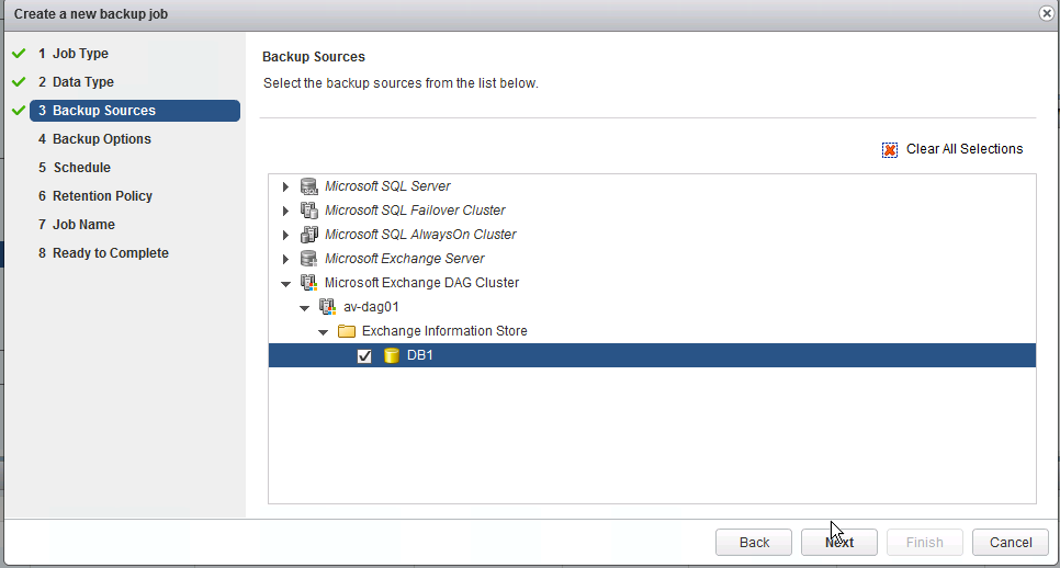
Figure 19. Select the Desired Exchange Mailbox Database
5. In Backup Options, enter the credentials for the Exchange environment. We set the DAG Backup Policy to Prefer Passive.

Figure 20. Enter the Credentials for the Exchange Environment
6. Select the optimal schedule

Figure 21. Select the Optimal Schedule
7. Select the retention policy

Figure 22. Select the Retention Policy
8. Enter a job name.

Figure 23. Enter a Job Name
9. Select Finish.
10. Initiate a manual backup.

Figure 24. Initiate a Manual Backup
Restore Scenario for a DAG Mailbox
1. We need to restore the CEO mailbox. Use the Exchange ECP to validate which Exchange Mailbox Database hosts the CEO’s mailbox. It is DB1 in this case.

Figure 25. CEO’s Mailbox
2. From the vSphere Data Protection plugin, select the restore point-in-time and drill down into mailbox database, and select the mailbox to restore.

Figure 26. Select the Mailbox to Restore
3. In Set Restore Options, select the destination Exchange Server.
4. In Set Restore Options, enter the client name.
5. Confirm and Finish.
Disaster Recovery with Site Recovery Manager
Overview
Using Site Recovery Manager with Exchange leverages replication techniques that are efficient cross-WAN seeding. Failover and failback steps are configurable and are automated with Site Recovery Manager. Site Recovery Manager facilitates disaster simulation for testing and validating the integrity of an organization’s disaster recovery plan, without interrupting mail flow, service availability, and continued client access in the production Exchange infrastructure.
Test Process
We performed the following steps to set up the DR plan for Microsoft Exchange Server on vSAN Cluster. After each step is set up and configured successfully, the protected virtual machines in the protection site can be recovered on the disaster recovery site.
- Install and set up the Site Recovery Manager on each site. For more information about how to install and configure Site Recovery Manager, see the VMware vCenter Site Recovery Manager 6.0 Documentation Center.
- Install and configure the vSphere Replication. For more information about how to install and configure vSphere Replication, see the VMware vSphere Replication 6.0 Documentation Center.
- Register vSphere Replication with the vCenter.
- Monitor the replication status of vSphere Replication.
To monitor the replication status and view information about virtual machines configured for vSphere Replication, log in to the vSphere Web Client, click vSphere Replication -> Sites -> Monitor -> vSphere Replication to check three items: outgoing replication, incoming replication, and reports. You can observe the monitoring status from the protection site (outgoing Replication) or the recovery site (incoming replication). Figure 27 shows the replication status of the protection site for the Exchange Server virtual machines. The virtual machine (ExcSvr4) completed the replication.
.png)
Figure 27. Replication Status of the Protection Site
The vSphere Replication report summarized the replication status, including replicated VMs, transferred bytes, RPO violations, replication count, site connectivity, and vSphere Replication server connectivity, as shown in Figure 28.
.png)
Figure 28. vSphere Replication Report
5. Create the protection group and recovery plan for the specified virtual machines as shown in Figure 29 and Figure 30. We only showed one of the four Exchange servers for the testing purpose.
.png)
Figure 29. Create the Protection Group
.png)
Figure 30. Create the Recovery Plan
6. Run the test plan to make sure the recovery site can take over the virtual machines in the protection group on the protection site. Figure 31 displays the completed test for the Exchange Server virtual machine with DAGs.
.png)
Figure 31. Test Complete
7. Clean up the recovery plan: click Site Recovery -> select Recovery Plans on the left pane -> select the specific recovery plan -> Actions -> Cleanup.
Summary and Recommendations
The functional summaries and recommendations are:
- vSAN provided a unified storage platform for both the protection and the recovery sites interoperating with Site Recovery Manager.
- The minimal RPO of the vSphere Replication can be 5 minutes to 1,440 minutes. vSphere Replication depends on the IP network to replicate the VMDK of the virtual machines, so the RPO might not be satisfactory if the network bandwidth cannot finish the replicated data within the timeframe and vSphere Replication reports an RPO violation. More bandwidth should be provided or the RPO policy should be increased to achieve the RPO goal.
- vSphere Replication replicated the virtual machines from one site to another, so the DNS server and IP network may change. The DNS redirection or modification is required to ensure that the virtual machines can work normally after the disaster recovery.
Resiliency Testing
Overview
This section validated vSAN resiliency in handling disk, double disk, and host failures. We designed the following scenarios to simulate potential real-world component failures:
-
Disk failure
This test evaluated the impact on the virtualized Exchange Server when encountering one HDD failure. The HDD stored the VMDK component of the user database. Hot-remove (or hot-unplug) one HDD to simulate permanent disk failure on one of the nodes of the vSAN Cluster to observe whether it has functional or performance impact on the production Exchange Server database.
-
Double disk failure
This test evaluated the impact on the virtualized Exchange Server when encountering double disk failure. Hot-remove two SSDs to simulate permanent double disk failure and to observe whether it has functional or performance impact on the production Exchange Server database.
-
Storage host failure
This test evaluated the impact on the virtualized Exchange Server when encountering one vSAN host failure. Shut down one host in the vSAN Cluster to simulate host failure to observe whether it has functional or performance impact on the production Exchange Server database.
Test Scenario and Result
Single Disk Failure
While all four hosts and applications were running simulated workload on vSAN, one disk from a host failed.
An ESXi host with running applications continued to function but the I/O was paused approximately one minute and then restarted. Use both vsan.disk_stats and vsan.resync_dashnoard to monitor the vSAN status and resync status.
During the single disk failure, Exchange Server was running a Jetstress test. ExchSvr1 was the Exchange Server with the Jetstress load as shown in Figure 32, we identified one of the supporting physical disks for one of ExchSvr1’s VMDKs and we removed it from the server. The component was non compliant with the SPBM as shown in Figure 32.
.png)
Figure 32. Exchange Server with the Jetstress Load in a Single Disk Failure
Figure 33 shows that the disk group reported an error message accordingly.
.png)
Figure 33. Disk Group Reported an Error Message
vSAN Observer notice the single disk failure. The latency and outstanding IOs increased on hosts .91 and .92, while the Exchange Jetstress I/O continued on .94 of the vSAN. Host .93 had no noticeable impact since there was no active I/O on the host as shown in Figure 34.
.png)
Figure 34. Latency and IOPS on vSAN Nodes in a Single Disk Failure
However, the Exchange Jetstress test still passed the test as shown in Figure 35 and Figure 36, despite the small spike in latency shown in Figure 34..png)
Figure 35. Exchange Jetstress Test Passed in Single Disk Failure
.png)
Figure 36. Transactional I/O Performance in a Single Disk Failure
Double Disk Failure
While all four hosts and applications were running the simulated workload on vSAN, two disks from a host failed as shown in Figure 37.
An ESXi host with running applications continued to function but the I/O was paused approximately one minute and then restarted. We used both vsan.disk_stats and vsan.resync_dashnoard to monitor the vSAN status and resync status.
.png)
Figure 37. Exchange Server with the Jetstress Load in a Double Disk Failure
vSAN Observer noticed the double disk failure. The latency and outstanding IOs increased on hosts .91 and .92, while the Exchange Jetstress I/O continued on .94 of the vSAN. Host .93 had no noticeable impact since there was no active I/O on the host as shown in Figure 38.
.png)
Figure 38 . Latency and IOPS on vSAN Nodes in a Double Disk Failure
The Exchange Server still passed the test as shown in Figure 39 and Figure 40.
.png)
Figure 39. Exchange Jetstress Test Passed in a Double Disk Failure
.png)
Figure 40 . Transactional I/O Performance in a Double Disk Failure
Host Failure
The third resiliency test was the host failure test. In this test, we reboot an ESXi host within the vSAN Cluster. We selected .91 during a Jetstress run and we reboot the host. The Exchange Jetstress test continued to run as noticed on hosts .91 and .93. Host .92 continued with a small amount of I/O but host .94 had relatively no I/O before and after the host reboot.
.png)
Figure 41. One Host Failure Test Result
The Exchange Server still passed the test as shown in Figure 42 and Figure 43.
.png)
Figure 42. Exchange Server Passed the Test in One Host Failure
.png)
Figure 43. Transactional I/O Performance in One Host Failure
In conjunction with the Jetstress testing, we were also able to send and receive emails during and after the testing. vSphere HA and DRS performed the necessary VM migrations and powered up the VMs that were previously on 10.20.177.91. Note that only one mailbox database was used in the failure tests. The Exchange Mailbox Database passive copies became active on their respective virtual machines. There was approximate one-minute delay in re-establishing connectivity to the newly activated Exchange Mailbox Database copy without user intervention.
In conclusion, when an ESXi node was powered off, VMware vSAN was capable of providing the necessary performance and VM-level resiliency to serve a tier-1 application such as Microsoft Exchange 2013.
Best Practices of Virtualized Exchange 2013 vSAN
This section highlights the best practices to be followed for Virtualized Exchange for vSAN.
A well-designed vSAN is crucial to the successful implementation of enterprise applications such as Exchange. The focus of this reference architecture is VMware vSAN storage best practices for Microsoft Exchange Server 2013. Refer to the Microsoft Exchange 2013 on VMware Best Practices Guide for detailed information on memory, CPU, and networking configurations.
Mailbox Server and DAG Sizing
For overall space requirements and individual disk sizing, use the Exchange 2013 sizing and capacity planning tool to determine what storage and server capacity is required for the proposed Exchange environment.
With the results from the Exchange sizing tool, planning can start for the vSAN architecture for Exchange. For example, in this reference architecture, 2,500 mailboxes at 2GB per mailbox with 250 messages per day and an average of 75KB per message was used for the calculation in the Exchange sizing tool. The total volume requirements are 18TB. Based on the results, we created a 4-node Exchange DAG with three active mail databases per server and three passive copies per server. The total raw capacity requirement for this configuration is 36TB. The required space increases with the SPBM of FTT=1.
VM Configuration and Disk Layout
According to the Microsoft Exchange 2013 on VMware Best Practices Guide, it is recommended to use Paravirtual SCSI adapters for each Exchange Mailbox Database and log disks. For example, this configuration uses six Mailbox Database disks and six log disks assigned to three different Paravirtual SCSI adapters.
| EXCHANGE ROLE | DRIVE LETTER/ MOUNT POINT | VIRTUAL HARDWARE PER VIRTUAL MACHINE |
|---|---|---|
| Mailbox Server – 4 Servers Normal Run Time – 1350 Mailboxes Each |
CPU 8 cores Memory - 64GB Storage – SCSI Controller 0: |
|
| C:\ | HDD 1 – 80GB (OS and application files) | |
| Storage – SCSI Controller 1: | ||
| E:\ | HDD 2 – 633GB (DB1) | |
| F:\ | HDD 3 – 60GB (LOG1) | |
| G:\ | HDD 4 – 633GB (DB2) | |
| H:\ | HDD 5 – 60GB (LOG2) | |
| Storage – SCSI Controller 2: | ||
| I:\ | HDD 6 – 633GB (DB3) | |
| J:\ | HDD 7 – 60GB (LOG3) | |
| K:\ | HDD 8 – 633GB (DB4) | |
| L:\ | HDD 9 – 60GB (LOG4). | |
| Storage – SCSI Controller 3: | ||
| M:\ | HDD 10 – 633GB (DB5) | |
| N:\ | HDD 11 – 60GB (LOG5) | |
| O:\ | HDD 12 – 633GB (DB6) | |
| P:\ | HDD 13 – 60GB (LOG6) | |
| Network – vNIC 1 – LAN/Client Connectivity | ||
| Network – vNIC 2 – LAN/Client Connectivity |
CPU Configuration Guidelines
This section provides guidelines for CPU configuration for Exchange virtual machines:
- Allocate multiple vCPUs to a virtual machine only if the anticipated Exchange workload can truly take advantage of all the vCPUs.
- If the exact workload is unknown, size the virtual machine with a smaller number of vCPUs initially, and increase the number later if necessary.
- For performance-critical Exchange virtual machines (production systems), the total number of vCPUs assigned to all the virtual machines should be equal to or less than the total number of physical cores on the ESXi host machine, not hyper-threaded cores.
- The recommended maximum CPU core count is 24.
- The recommended maximum memory is 96GB.
Although larger virtual machines are possible in vSphere, VMware recommends reducing the number of virtual CPUs if monitoring of the actual workload shows that the Exchange application is not benefiting from the increased virtual CPUs. Exchange sizing tools tend to provide conservative recommendations for CPU sizing. As a result, virtual machines sized for a specific number of mailboxes might be underutilized. See Microsoft Exchange 2013 on VMware Best Practices Guide for more information.
Memory Configuration Guidelines
This section provides guidelines for memory allocation to Exchange virtual machines. These guidelines consider vSphere memory overhead and the virtual machine memory settings.
Microsoft has developed a thorough sizing methodology for Exchange Server that has matured with recent versions of Exchange. VMware recommends using the memory sizing guidelines set by Microsoft. The amount of memory required for an Exchange Server is driven by its role.
Because Exchange Servers are memory-intensive and performance is a key factor in production environments, VMware recommends the following practices:
- Do not over commit memory on ESXi hosts running Exchange workloads. For production systems, it is possible to enforce this policy by setting a memory reservation to the configured size of the virtual machine. Also note that
- Setting memory reservations might limit VMware vSphere vMotion. A virtual machine can only be migrated if the target ESXi host has free physical memory equal to or greater than the size of the reservation.
- Setting the memory reservation to the configured size of the virtual machine results in a per-virtual machine VMkernel swap file of zero bytes that consumes less storage and eliminates ESXi host-level swapping. The guest operating system within the virtual machine still requires its own page file.
- Reservations are only recommended when it is possible that memory might become overcommitted on hosts running Exchange virtual machines, when SLAs dictate that memory is “guaranteed,” or when there is a desire to reclaim space used by a virtual machine swap file.
- It is important to right size the configured memory of a virtual machine. Understand the expected mailbox profile and recommended mailbox cache allocation to determine the best starting point for memory allocation. To determine the specific Exchange Server memory requirements, refer to Exchange 2013 Sizing and Configuration Recommendations and Exchange Server Role Requirements Calculator.
- Do not deactivate the balloon driver (which is installed with VMware Tools™).
- Enable DRS to balance workloads in the ESXi host cluster. DRS and reservations can give critical workloads the resources they require to operate optimally. DRS provides rules for keeping virtual machines apart or together on the same ESXi host or group of hosts. In an Exchange environment, the common use case for anti-affinity rules is to keep Exchange virtual machines with the same roles installed apart from each other. Client Access servers in a CAS array can run on the same ESXi host, but DRS rules should be used to prevent all CAS virtual machines from running on a single ESXi host. For more recommendations for using DRS with Exchange 2013, see the Using vSphere Technologies with Exchange 2013 chapter in the Microsoft Exchange 2013 on VMware Best Practices Guide.
Networking Configuration Guidelines
This section covers design guidelines for the virtual networking environment and provides configuration examples at the ESXi host level for Exchange Server 2013 installations.
The virtual networking layer includes virtual network adapters and the virtual switches. Virtual switches are the key networking components in vSphere.
We also isolate the MAPI and DAG traffic from all other traffic. Additionally, we take advantage of the DvPortGroups feature and create port groups for both MAPI and public VM traffic using VLAN 101.
In addition to the Exchange required networks, it is a best practice for VMware vSAN to have a separate cluster management network. Refer to the VMware vSAN Network Design Guide for more information.
Note: The examples do not reflect design requirements and do not cover all possible Exchange network design scenarios.

Figure 44. Virtual Network Configuration—Exchange DAG
Conclusion
This section provides a summary that validates vSAN as a storage platform supporting a scalable and high performing Microsoft Exchange DAG Cluster.
vSAN is a resilient and high-performance storage platform that is rapidly deployed, easy to manage, and fully integrated into the industry-leading VMware vSphere Cloud Suite.
This solution validated vSAN as a storage platform supporting a scalable and high performing Microsoft Exchange DAG Cluster.
vSAN’s ease of use allows Exchange administrators to deploy and manage day-to-day operations from a single management interface. vSphere Data Protection enables simple and robust backup and recovery solution integrated with vCenter and Microsoft Exchange. Site Recovery Manager provides a disaster recovery plan built in and automated within vCenter that can be tested before an outage, planned maintenance, or periodically in preparation for a disaster situation. Using VMware’s Site Recovery Manager and vSphere Data Protection provides a resilient and highly available Microsoft Exchange 2013 environment.
Reference
This section lists the relevant references used for this document.
White Paper
For additional information, see the following white paper:
Product Documentation
For additional information, see the following product documentation:
- VMware vCenter Site Recovery Manager 6.0 Documentation Center
- VMware vSphere Replication 6.0 Documentation Center
- VMware Site Recovery Manager 6.1
Other References
For additional information, see the following documents:
About the Author and Contributors
This section provides a brief background on the author and contributors of this operation guide.
Christian Rauber, solution architect in the vSAN Product Enablement team wrote the original version of this paper. Catherine Xu, technical writer in the vSAN Product Enablement team, edited this paper to ensure that the contents conform to the VMware writing style.
Contributors to this document include:
- Bradford Garvey, storage solution architect in the vSAN Product Enablement team
- Deji Akomolafe, solution architect in the Global Technology and Professional Services team
- Weiguo He, director of the vSAN Product Enablement team