Microsoft Exchange Server on VMware vSphere
Introduction
Concurrent usage of the Exchange Server native high availability feature (Database Availability Group or DAG) with VMware vSphere® native high availability features has been fully and unconditionally supported by Microsoft since Exchange Server 2019. Microsoft continues the trend by extending this declarative statement of support for virtualization to the 2019 version of Exchange Server.
Because the vSphere hypervisor is part of the Microsoft Server Virtualization Validation Program (SVVP), virtualizing an Exchange Server 2019 instance on vSphere is fully supported.
This document provides technical guidance for VMware customers who are considering virtualizing their Exchange Server on the vSphere virtualization platform.
Enterprise communication and collaboration is now so integral to an organization’s operations that applications such as Exchange Server are now routinely classified as mission-critical. Organizations expect measurable and optimal performance, scalability, reliability, and recoverability from this class of applications. The main objective of this guide is to provide the information required to help a customer satisfy the operational requirements of running Exchange Server 2019 on all currently shipping and supported versions of VMware vSphere up to vSphere version 7.0.
Purpose
This guide provides best practice guidelines for deploying Exchange Server 2019 on vSphere. The recommendations in this guide are not specific to any particular hardware, nor to the size and scope of any particular Exchange implementation. The examples and considerations in this document provide guidance but do not represent strict design requirements, as the flexibility of Exchange Server 2019 on vSphere allows for a wide variety of valid configurations.
Target Audience
This guide assumes a basic knowledge and understanding of vSphere and Exchange Server 2019.
- Architectural staff can use this document to gain an understanding of how the system will work as a whole, as they design and implement various components.
- Engineers and administrators can use this document as a catalog of technical capabilities.
- Messaging staff can use this document to gain an understanding of how Exchange might fit into a virtual infrastructure.
- Management staff and process owners can use this document to help model business processes to take advantage of the savings and operational efficiencies achieved with virtualization.
Scope
The scope of this document is limited to the following topics:
- VMware ESXi™ Host Best Practices for Exchange – Best practice guidelines for preparing the vSphere platform for running Exchange Server 2019. Guidance is included for CPU, memory, storage, and networking.
- Using VMware vSphere vMotion®, VMware vSphere Distributed Resource Scheduler™ (DRS), and VMware vSphere High Availability (HA) with Exchange Server 2019 – Overview of vSphere vMotion, vSphere HA, and DRS, and guidance for usage of these vSphere features with Exchange Server 2019 virtual machines (VM).
- Exchange Performance on vSphere – Background information on Exchange Server performance in a VM. This section also provides information on official VMware partner testing and guidelines for conducting and measuring internal performance tests.
- VMware Enhancements for Deployment and Operations – A brief look at vSphere features and add-ons that enhance deployment and management of Exchange Server 2019.
The following topics are out of scope for this document.
- Design and Sizing Guidance – Historically, sizing an Exchange environment is a guessing game, even after using the Exchange Server Role Requirements Calculator (also known as Exchange Calculator) available from Microsoft. As of this writing, Microsoft has not updated the Exchange Calculator to include sizing considerations for Exchange Server 2019. This gap makes it especially critical for customers to be judicious in baselining their Exchange Server sizing exercise – to not only ensure that they allocate adequate resources to the Exchange Server workloads, but to also ensure they do not unnecessarily over-allocate such resources.
This and other guides are limited in focus to deploying Microsoft Exchange Server workloads on VMware vSphere. Exchange deployments cover a wide subject area, and Exchange-specific design principles should always follow Microsoft guidelines for best results.
External References
This document includes references to external links on third-party websites for the purposes of clarifying statements where necessary. While these statements were accurate at the time of publishing, these third-party websites are not under VMware control. This third-party content is subject to change without prior notification.
ESXi Host Best Practices for Exchange
A well-designed VMware vSphere hypervisor platform is crucial to the successful implementation of virtualized enterprise applications such as Exchange Server. The following sections outline general best practices for designing vSphere for Exchange Server 2019.
CPU Configuration Guidelines
The latest release of vSphere (vSphere 7.0) has dramatically increased the scalability of VMs, enabling configurations of up to 768 virtual processors for a single VM. With this increase, one option to improve performance is to simply create larger VMs. However, additional considerations are involved in deciding how much processing power should be allocated to a VM. This section reviews features that are available in vSphere with regard to virtualizing CPUs. Where relevant, this document discusses the impact of those features to Exchange Server 2019 and the recommended practices for using those features.
Physical and Virtual CPUs
VMware uses the terms virtual CPU (vCPU) and physical CPU (pCPU) to distinguish between the processors within the VM and the underlying physical processor cores. VMs with more than one vCPU are also called symmetric multiprocessing (SMP) VMs. The virtual machine monitor (VMM) is responsible for virtualizing the CPUs. When a VM begins running, control transfers to the VMM, which is responsible for virtualizing guest operating system instructions.
Architectural Limitations in Exchange Server
Microsoft provides guidelines to calculate the required compute resources for a single instance of Exchange Server (as an application) so that Exchange Servers do not experience unintended performance degradation due to incorrect sizing. These maximums are the same whether the Exchange Server is virtualized or installed on physical servers.
See the following table.
Table 1. Exchange Server Maximum Supported Compute Resource
| Configuration Item | Maximum Supported |
| Memory Per Exchange Server Instance | 256 GB |
| Number of CPUs per Exchange Server Instance | 2 Sockets |
vSphere Virtual Symmetric Multiprocessing
VMware virtual symmetric multiprocessing (vSMP) enhances VM performance by enabling a single VM to use multiple physical processor cores simultaneously. The most recent version of vSphere (version 7.0 as of the time of publishing) supports allocating up to 768 virtual CPUs per VM. The biggest advantage of an SMP system is the ability to use multiple processors to execute multiple tasks concurrently, thereby increasing throughput (e.g., the number of transactions per second). Only workloads that support parallelization (including multiple processes or multiple threads that can run in parallel) can benefit from SMP.
Be aware of the maximum 2-sockets requirement for Exchange Server 2019 when making a sizing decision. The ability to allocate up to 768 vCPUs to a VM should be less important in this context. VMware strongly recommends allocating resources to a VM based on the actual needs of the applications hosted on the VM.
The ESXi scheduler uses a mechanism called relaxed co-scheduling to schedule processors. Strict co-scheduling requires all vCPUs to be scheduled on physical cores simultaneously, whereas relaxed co-scheduling monitors time skew between vCPUs to make scheduling or co-stopping decisions. A leading vCPU might decide to co-stop itself to allow for a lagging vCPU to catch up. Consider the following points when using multiple vCPUs:
- VMs with multiple vCPUs perform well in the latest versions of vSphere, as compared with older versions where strict co-scheduling was used.
- Regardless of relaxed co-scheduling, the ESXi scheduler prefers to schedule vCPUs together, when possible, to keep them in sync. Deploying VMs with multiple vCPUs that are not used wastes resources and might result in reduced performance of other VMs.
For detailed information regarding the CPU scheduler and considerations for optimal vCPU allocation, please see the section on ESXi CPU considerations in Performance Best Practices for VMware vSphere 7.0.
- VMware recommends allocating multiple vCPUs to a VM only if the anticipated Exchange workload can truly take advantage of all the vCPUs.
- Use the Microsoft-provided Exchange Server Role Requirements Calculator tool to aid in your sizing exercise.
Note the following:- The Exchange calculator is intentionally generous in its recommendations and limits. The recommendations might not be optimal for a virtualized workload.
- The calculator does not factor in the Non-Uniform Memory Access (NUMA) topology of a given hardware when making compute resource recommendations. While Exchange Server (as an application) is unaware of NUMA optimization, VMware still recommends sizing a VM with the physical NUMA topology in mind. See Section 2.1.8, Non-Uniform Memory Access.
- The calculator assumes a 10% hypervisor overhead in its computation. Although VMware testing indicates a variation of 3%-5% in a worst-case performance scenario, VMware recommends not changing this value in the calculator when modelling Exchange Server 2019 VMs for capacity. Given the relative age of Exchange Server 2019, the true impact of the hypervisor on Exchange Server 2019 is currently unknown. Leaving this value unchanged helps customers remain as compliant as possible with Microsoft requirements.
- If the exact workload is not known, size the VM with a smaller number of vCPUs initially and increase the number later, if necessary.
- Microsoft supports up to 2:1 virtual-to-physical CPU allocation for Exchange Server 2019 in a virtual environment. VMware recommends that, for the initial sizing of performance-critical Exchange VMs (production systems), the total number of vCPUs assigned to all the VMs be no more than the total number of physical cores on the ESXi host machine, not hyper-threaded cores. By following this guideline, you can gauge performance and utilization within the environment until you are able to identify potential excess capacity that could be used for additional workloads.
- Although larger VMs are possible in vSphere, VMware recommends reducing the number of virtual CPUs for a VM if monitoring of the actual workload shows that the Exchange application is not benefitting from the increased vCPUs.
CPU Reservations
Setting a CPU reservation sets a guaranteed CPU allocation for the VM. This practice is generally not recommended because reserved resources are not available to other VMs and flexibility to manage changing workloads is restricted. However, SLAs and multitenancy may require a guaranteed amount of compute resource to be available. In these cases, reservations can be used. VMware has conducted tests on vCPU over-commitment with SAP and Microsoft SQL Server workloads, demonstrating that performance degradation inside the VMs is linearly reciprocal to the over-commitment. Because the performance degradation is graceful, any vCPU over-commitment can be effectively managed by using DRS and vSphere vMotion to move VMs to other ESXi hosts to obtain more processing power.
Virtual Cores and Virtual Sockets
vSphere now supports configuration of the number of virtual cores per virtual socket in the VMware vSphere Web Client. This feature provides two functions:
- When used with virtual Non-Uniform Memory Access (vNUMA)-enabled VMs, this setting can be used to present specific NUMA topologies to the guest operating system.
- More commonly, this feature allows a guest operating system to utilize all of its assigned vCPUs in the case of an operating system that is limited to a certain number of CPUs.
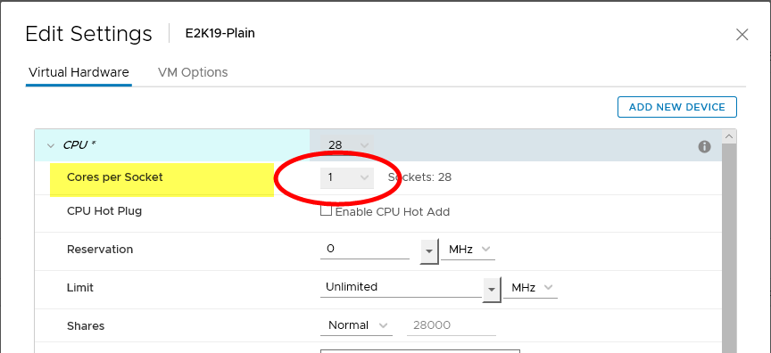
On vSphere, vCPUs can be allocated to a VM by socket, or by number of cores per socket. Historically, VMware had been recommending that, for performance considerations, the number of vCPUs allocated to a VM should be allocated using the “Sockets” options in a vSphere environment. Customers were encouraged to leave the “Cores per Socket” option unchanged from its default value of “1”. Controlling vCPUs by number of cores was a configuration option intended to help customers overcome the limitations in previous versions of the Windows operating system.
Figure 1. Previous Virtual Machine CPU Allocation Recommendation
Since Exchange Server 2019 requires a minimum OS version of Windows Server 2019, and the operating system does not suffer from the same socket limitations of prior Windows versions, it is logical to assume that previous guidance to “leave cores-per-socket at default” would persist. This is no longer valid, however, due to the architectural changes and optimizations VMware has made to CPU scheduling algorithms in newer versions of vSphere (since version 6.5).
VMware now recommends that, when presenting vCPUs to a VM, customers should allocate the vCPUs in accordance with the PHYSICAL NUMA topology of the underlying ESXi Host. Customers should consult their hardware vendors (or the appropriate documentation) to determine the number of sockets and cores physically present in the server hardware and use that knowledge as operating guidance for VM CPU allocation. The recommendation to present all vCPUs to a VM as “sockets” is no longer valid in modern vSphere/ESXi versions.
The following is a high-level representation of the new vCPU allocation for VMs in a vSphere version 6.5 infrastructure and newer.
Figure 2. New Virtual Machine CPU Allocation Recommendation
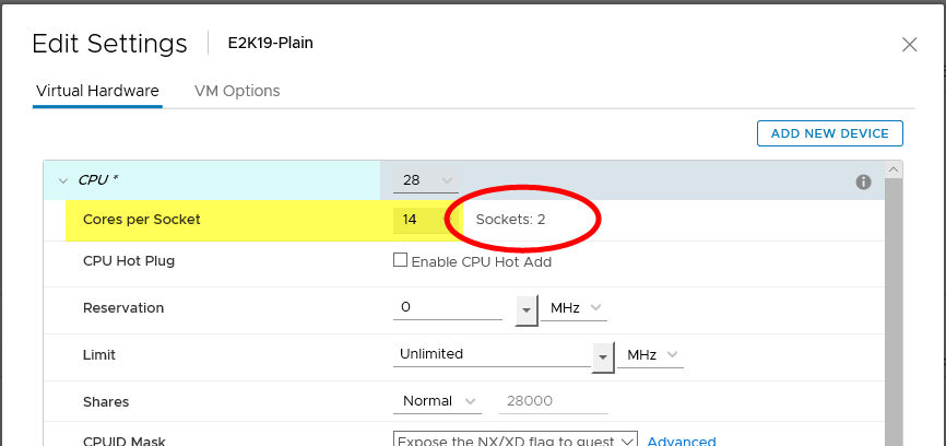
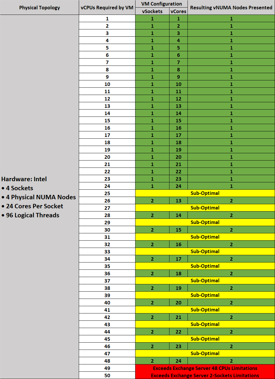
VMs, including those running Exchange Server 2019, should be configured with multiple virtual sockets and cores which, together, equal the number of vCPUs intended. This sockets-cores combination should reflect the topology of the sockets-cores present on the motherboard.
Where the number of vCPUs intended for a VM is not greater than the number of cores present in one physical socket, all of the vCPUs so allocated should come from one socket. Conversely, if a VM requires more vCPUs than are physically available in one physical socket, the desired number of vCPUs should be evenly divided between two sockets.
NOTE: The 2-socket prescription is based on Microsoft’s restated requirements for a single Exchange Server.
While VMs using vNUMA may benefit from this option, the recommendation for these VMs is to use virtual sockets (CPUs in the web client). Exchange Server 2019 is not a NUMA-aware application and performance tests have shown no significant performance improvements by enabling vNUMA. However, Windows Server 2019 OS is NUMA-aware and Exchange Server 2019 (as an application) does not experience any performance, reliability, or stability issues attributable to vNUMA.
Hyper-threading
Hyper-threading technology (recent versions are called symmetric multithreading, or SMT) allows a single physical processor core to behave like two logical processors, so that two independent threads are able to run simultaneously. Unlike having twice as many processor cores that can roughly double performance, hyper-threading can provide anywhere from a slight to a significant increase in system performance by keeping the processor pipeline busier. For example, an ESXi host system enabled for SMT on an 8-core server sees 16 threads that appear as 16 logical processors.
Previous guidance provided by Microsoft regarding Exchange sizing and the use of hyper-threading led to some confusion among those looking at virtualizing Exchange Server. Microsoft has since updated all applicable documents to clarify that statements relating to hyper-threading and Exchange Server do not apply to virtualization platforms. Microsoft’s guidance in this respect is expected to complement Microsoft’s “Preferred Architecture” design option, which does not incorporate any virtualization design choices, options or considerations. See Ask The Perf Guy: What’s The Story With Hyper-threading and Virtualization? for the most recent guidance from Microsoft.
vSphere uses hyper-threads to provide more scheduling choices for the hypervisor. Hyper-threads provide additional targets for worlds, a schedulable CPU context that can include a vCPU or hypervisor management process. For workloads that are not CPU-bound, scheduling multiple vCPUs onto a physical core’s logical cores can provide increased throughput by increasing the work in the pipeline. The CPU scheduler schedules to a whole core over a hyper-thread, or partial core, if CPU time is lost due to hyper-thread contention. Consequently, VMware recommends enabling hyper-threading on the ESXi host if the underlying hardware supports the configuration.
“L1 Terminal Fault – VMM” and Hyper-threading
For customers concerned about the effects of the Speculative-Execution vulnerability in Intel processors for vSphere (CVE-2018-3646) issue on virtualized workloads, VMware has provided the following resources documenting the recommended resources and tools for mitigation:
- VMware response to ‘L1 Terminal Fault - VMM’ (L1TF - VMM) Speculative-Execution vulnerability in Intel processors for vSphere
- HTAware Mitigation Tool Overview and Usage
VMware recommends that customers do not disable hyper-threading as doing so precludes potential vSphere scheduler enhancements and mitigations that will allow the use of both logical processors of a hyper-thread-capable core. Disabling hyper-threading to mitigate the concurrent-context attack vector will introduce unnecessary operational overhead, as hyper-threading may need to be re-enabled in subsequent vSphere updates.
Non-Uniform Memory Access
In NUMA systems, a processor or set of processor cores has access to memory with very little latency. The memory and its associated processor or processor cores are referred to as a NUMA node. NUMA-aware operating systems and applications can make decisions as to where a process might run relative to the NUMA architecture. This allows processes to access memory local to the NUMA node rather than having to traverse an interconnect and incur additional latency. Exchange Server 2019 is not NUMA-aware, but both ESXi and Windows Server 2019 are.
vSphere ESXi provides mechanisms for letting VMs take advantage of NUMA. The first mechanism is transparently managed by ESXi while it schedules a VM’s virtual CPUs on NUMA nodes. By attempting to keep all of a VM’s vCPUs scheduled on a single NUMA node, memory access can remain local. For this to work effectively, size the VM to fit within a single NUMA node. This placement is not a guarantee, however, as the scheduler migrates a VM between NUMA nodes based on the demand.
The second mechanism for providing VMs with NUMA capabilities is vNUMA. When enabled for vNUMA, a VM is presented with the NUMA architecture of the underlying hardware. This allows NUMA-aware operating systems and applications to make intelligent decisions based on the underlying host’s capabilities. By default, vNUMA is automatically enabled for VMs with nine or more vCPUs on vSphere. Because Exchange Server 2019 is not NUMA-aware, enabling vNUMA for an Exchange VM does not provide any additional performance benefit, nor does doing so incur any performance degradation.
Consider sizing Exchange Server 2019 VMs to fit within the size of the physical NUMA node for best performance. The following figure depicts an ESXi host with four NUMA nodes, each comprising 20 physical cores and 128GB of memory. The VM allocated with 20 vCPUs and 128 GB of memory can be scheduled by ESXi onto a single NUMA node. Likewise, a VM with 40 vCPUs and 256 GB RAM can be scheduled on 2 NUMA nodes.
Figure 3. NUMA Architecture Sizing Scenarios
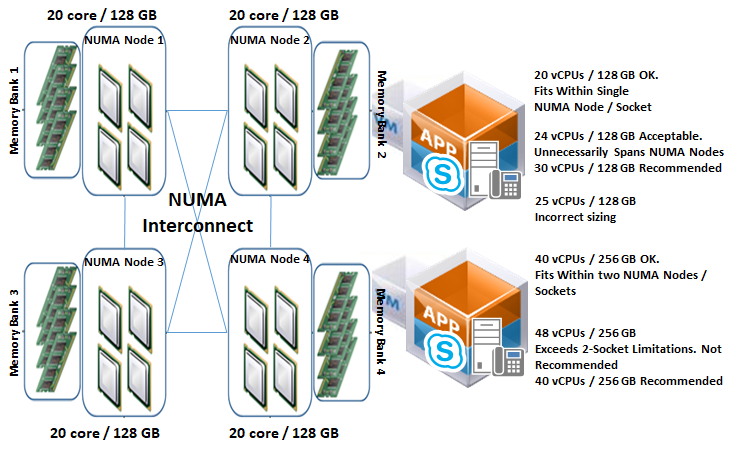
A VM allocated with 24 vCPUs and 128 GB of memory must span NUMA nodes in order to accommodate the extra four vCPUs, which might then cause the VM to incur some memory access latency as a result of four vCPUs outspanning a single NUMA node. The associated latency can be minimized or avoided through the use of the appropriate combination of vNUMA control options in the VM’s Advanced Configuration options. See Specifying NUMA Control in the VMware vSphere Resource Management Guide.
While a VM allocated with 48 vCPUs and 256 GB can evenly span multiple NUMA nodes without incurring the memory access latency issues described earlier, such a configuration is neither recommended nor supported because the number of NUMA nodes (sockets) required to accommodate the configuration exceeds Microsoft’s maximum 2-sockets recommendation.
For large environments, VMware strongly recommends that customers thoroughly test each configuration scenario to determine whether additional latency associated with remote memory-addressing warrants creating additional, smaller rather than larger VMs.
Verify that all ESXi hosts have NUMA enabled in the system BIOS. In some systems, NUMA is enabled by disabling node interleaving.
vNUMA and CPU Hot Plug
Enabling CPU hot add for a VM on vSphere disables vNUMA for the VM. As Exchange Server does not benefit from either vNUMA or CPU hot add, VMware recommends that CPU hot add for an Exchange Server 2019 VM should not be enabled.
Memory Configuration Guidelines
This section provides guidelines for memory allocation to Exchange Server 2019 VMs. These guidelines consider vSphere memory overhead and VM memory settings.
ESXi Memory Management Concepts
vSphere virtualizes guest physical memory by adding an extra level of address translation. Shadow page tables make it possible to provide this additional translation with little or no overhead. Managing memory in the hypervisor enables the following:
- Memory-sharing across VMs that have similar data – same guest operating systems
- Memory over-commitment – allocating more memory to VMs than is physically available on the ESXi host
- A memory-balloon technique – VMs that do not need all of their allocated memory give memory to VMs that require it
For a more detailed discussion of vSphere memory-management concepts, see the Memory Virtualization Basics and Administering Memory Resources sections in the vSphere Resource Management Guide for more detailed information.
Virtual Machine Memory Concepts
The following figure illustrates the use of memory settings parameters in the VM.
Figure 4. Virtual Machine Memory Settings
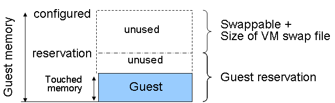
The vSphere memory settings for a VM include the following parameters:
- Configured memory – memory size of VM assigned at creation
- Active Memory – the amount of physical memory that is being used by VMs in a vSphere infrastructure. vSphere allocates guest operating system memory on demand.
- Swappable – VM memory that can be reclaimed by the balloon driver or by vSphere swapping. Ballooning occurs before vSphere swapping. If this memory is in use by the VM (touched and in use), the balloon driver causes the guest operating system to swap. Also, this value is the size of the per-VM swap file that is created on the VMware vSphere Virtual Machine File System (VMFS).
- If the balloon driver is unable to reclaim memory quickly enough, or is disabled or not installed, vSphere forcibly reclaims memory from the VM using the VMkernel swapping mechanism.
Memory Tax for Idle Virtual Machines
It is a common practice for Exchange Server administrators to allocate as many resources as possible to an Exchange Server (subject to the supported maximum prescribed by Microsoft). Administrators typically do so to prepare for a "worst-case demand" scenario, minimizing the administrative interventions required in unexpected cases of increased loads and pressure on a production Exchange Server infrastructure. In a physical Exchange Server environment, such preparation is usually advisable and not problematic. However, VMware highly recommends against this practice for virtualized Exchange Servers running in a vSphere infrastructure. This is due to the implications of unintended penalties associated with over-allocating memory to VMs in a vSphere environment.
If a VM is not actively using all of its currently allocated memory, ESXi charges more for idle memory than for memory that is in use. This is done to help prevent VMs from hoarding idle memory. The idle memory tax is applied in a progressive fashion. The effective tax rate increases as the ratio of idle memory to active memory for the VM rises. VMware strongly recommends that vSphere and Exchange Server administrators allocate only as many resources as are required by Exchange Server workloads, rather than allocating resources for worst-case scenarios. Using the Exchange Calculator and thoroughly testing the recommended sizing in a controlled (pre-production) environment is the best way for administrators to determine the proper amount of memory resources to allocate to a VM.
If necessary, customers can modify the idle memory tax rate by adjusting the VM’s Mem.IdleTax advanced configuration option. When combined with the Mem.SamplePeriod option, customers are able to control how the vSphere determines target memory allocations for VMs in the infrastructure.
Allocating Memory to Exchange Virtual Machines
Microsoft has developed a thorough sizing methodology for Exchange Server that has matured with recent versions. VMware recommends using the memory-sizing guidelines set by Microsoft. The amount of memory required for Exchange Server 2019 is driven by the expected size of loads that will be generated and the total number of Exchange Servers that will support the loads in the environment. Load characteristics include (but are not limited to) the following:
- Number of mailbox users
- Profile of mailbox usage pattern (size and number of emails sent and received)
- Type and number of devices used for accessing emails
- Anti-virus and other messaging security and hygiene solutions deployed on the server
- Type and frequency of backup solution in use
- High availability and resilience requirements
As Exchange Servers are memory-intensive, and performance is a key factor, such as in production environments, VMware recommends the following practices:
- Do not overcommit memory on ESXi hosts running Exchange workloads. If memory over-commitment cannot be avoided, use vSphere memory-allocation options to guarantee required memory size to the Exchange Server, or to limit memory access for other, non-essential VMs in the vSphere cluster.
- For production systems, it is possible to achieve this objective by setting a memory reservation to the configured size of the Exchange Server VM.
Note the following:
- Setting memory reservations might limit vSphere vMotion. A VM can be migrated only if the target ESXi host has free physical memory equal to or greater than the size of the reservation.
- Setting the memory reservation to the configured size of the VM results in a per-VM VMkernel swap file of near zero bytes that consumes less storage and eliminates ESXi host-level swapping. The guest operating system within the VM still requires its own page file.
- Reservations are recommended only when it is possible that memory might become overcommitted on hosts running Exchange VMs, when SLAs dictate that memory be guaranteed, or when there is a desire to reclaim space used by a VM swap file.
- There is a slight, appreciable performance benefit to enabling memory reservation, even if memory over-commitment in the vSphere cluster is not expected.
- It is important to right-size the configured memory of a VM. This might be difficult to determine in an Exchange environment because the Exchange JET cache is allocated based on memory present during service start-up. Understand the expected mailbox profile and recommended mailbox cache allocation to determine the best starting point for memory allocation.
- Do not disable the balloon driver (which is installed with VMware Tools™) or any other ESXi memory-management mechanism.
Note the following:
- Transparent Page Sharing (TPS) enables ESXi hosts to more efficiently utilize its available physical memory to support more workloads. TPS is useful in scenarios where multiple VM siblings share the same characteristics (e.g., the same OS and applications). In this configuration, vSphere is able to avoid redundancy by sharing similar pages among the different Exchange Server VMs. This sharing is transparent to the applications and processes inside the VM.
For security reasons, inter-VM page-sharing is disabled by default on current versions of vSphere. While a VM continues to benefit from TPS in this configuration (i.e., the VM is able to share pages internally among its own processes and components), a greater benefit can be realized by enabling inter-VM page-sharing. See Sharing Memory Across Virtual Machine in the vSphere Resource Management Guide.
Enable DRS to balance workloads in the ESXi host cluster. DRS and reservations can give critical workloads the resources they require to operate optimally. More recommendations for using DRS with Exchange Server 2019 are available in the Using vSphere Technologies with Exchange Server 2019 section below.
Memory Hot Add, Over-subscription, and Dynamic Memory
vSphere exposes the ability to add memory to a VM while the VM is powered on. Modern operating systems, including Windows, support this feature and are able to instantaneously detect and use the hot-added memory.
vSphere enables an administrator to allocate virtual memory to VMs beyond the physically available memory size of the ESXi host. This condition is called over-allocation, or over-subscription. Over-subscription is possible and non-intrusive, and is an essential core benefit of virtualization, as repeated testing has shown that VMs do not all fully utilize their allocated resources at the same time. If all VMs request their resources at the same time at any point in time, resource over-commitment on the ESXi or cluster occurs.
Transient resource over-commitment is possible within a virtual environment. Frequent or sustained occurrence of such incidents is problematic for critical applications such as Exchange Server.
Dynamic memory is a Microsoft Hyper-V construct that does not have a direct equivalence on vSphere. Even in an over-commitment scenario, the VM on vSphere is never induced to believe that its allocated memory has been physically reduced. vSphere uses other memory-management techniques for arbitrating contentions during a resource over-commitment condition.
Microsoft Exchange Server’s JET cache is allocated based on the amount of memory available to the operating system at the time of service start-up. After being allocated, the JET cache is distributed among active and passive databases. With this model of memory pre-allocation for use by Exchange databases, adding memory to a running Exchange VM provides no additional benefit unless the VM was rebooted or Exchange services restarted. Consequently, memory hot-add is neither useable by nor beneficial to an Exchange Server VM and is therefore neither recommended nor supported. In contrast, removing memory JET has allocated for database consumption impacts performance of the store worker and indexing processes by increasing processing and storage I/O.
Microsoft support for the virtualization of Exchange Server 2019 states that the over-subscription and dynamic allocation of memory for Exchange VMs is not supported. To help avoid confusion, refer to the preceding paragraphs to understand why these requirements are not relevant to Exchange Servers virtualized on the vSphere platform.
Over-subscription is different from over-commitment. Over-subscription is benign and does not impact VMs. Over-commitment is the adverse extension of over-subscription and should be avoided in all cases. However, if it’s expected that an ESXi cluster may occasionally experience resource contention as a result of memory over-commitment, VMware recommends judiciously reserving all memory allocated to Exchange Server VMs.
Because ESXi does not support hot-unplug (i.e., hot removal) of memory from a Windows VM, the only way to reduce the amount of memory presented to a VM running Exchange Server 2019 is to power off the VM and change the memory allocation. When the VM powers on again, the OS will see the new memory size, and Exchange Server will reallocate the available memory to its worker processes. This is not dynamic memory.
Storage Virtualization
VMFS is a cluster file system that provides storage virtualization optimized for VMs. Each VM is encapsulated in a small set of files and VMFS is the default storage system for these files on physical SCSI disks and partitions. VMware supports Fiber Channel, iSCSI, and network-attached storage (NAS) shared-storage protocols.
It is preferable to deploy VM files on shared storage to take advantage of vSphere vMotion, vSphere HA, and DRS. This is considered a best practice for mission-critical Exchange Server deployments that are often installed on third-party, shared-storage management solutions.
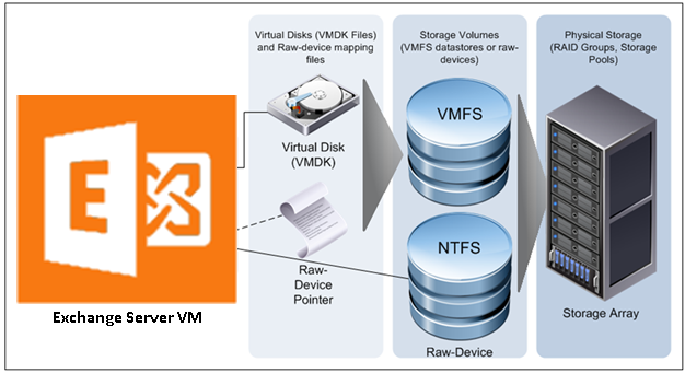
VMware storage virtualization can be categorized into three pillars of storage technology, as illustrated in the following figure. The storage array is the physical storage pillar, comprising physical disks presented as logical storage volumes in the next pillar. Storage volumes, presented from physical storage, are formatted as VMFS datastores or with native file systems when mounted as raw device mappings. VMs consist of virtual disks or raw device mappings that are presented to the guest operating system as SCSI disks that can be partitioned and formatted using any supported file system.
Figure 5. VMware Storage Virtualization
Exchange Server has improved significantly in recent releases and Exchange Server 2019 continues those improvements, making Exchange Server less storage I/O intensive than before. This reality informs Microsoft’s preference for commodity-class direct-attached storage (DAS) for Exchange Server. While the case for DAS and JBOD storage for Exchange appears reasonable from an I/O perspective, the associated operational and administrative overhead for an enterprise-level production Exchange Server infrastructure do not justify this guidance.
To overcome the increased failure rate and shorter lifespan of commodity storage, Microsoft routinely recommends maintaining multiple copies of Exchange data across larger sets of storage and Exchange Servers than operationally necessary.
While VMware supports the use of converged storage solutions for virtualizing Exchange Server on vSphere, VMware recommends that customers using such solutions thoroughly benchmark and validate the suitability of such solutions and engage directly with the applicable vendors for configuration, sizing, performance and availability guidance.
Even with the reduced I/O requirements of an Exchange Server instance, without careful planning, storage access, availability and latencies can still manifest in an Exchange server infrastructure.
VMware recommends setting up a minimum of four paths from an ESXi host to a storage array. To accomplish this, the host requires at least two host bus adapter (HBA) ports.
Figure 6. Storage Multi-pathing Requirements for vSphere
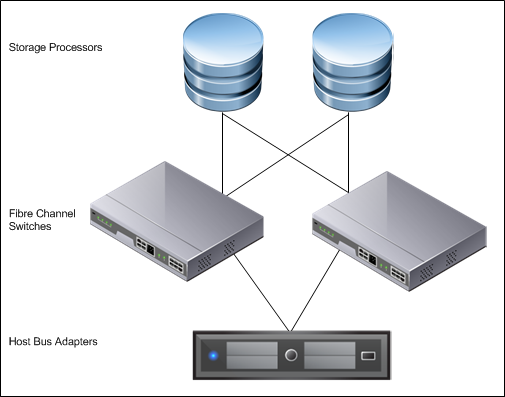
The terms used in the preceding figure are:
- HBA – a device that connects one or more peripheral units to a computer and manages data storage and I/O processing
- Fibre Channel (FC) – a gigabit-speed networking technology used to build storage area networks (SANs) and transmit data
- Storage Processor (SP) – a SAN component that processes HBA requests routed through an FC switch and handles the RAID/volume functionality of the disk array
Raw Device Mapping
VMFS also supports raw device mapping (RDM). RDM allows a VM to directly access a volume on the physical storage subsystem and can be used only with Fiber Channel or iSCSI. RDM provides a symbolic link or mount point from a VMFS volume to a raw volume. The mapping makes volumes appear as files in a VMFS volume. The mapping file, rather than the raw volume, is referenced in the VM configuration. Connectivity from the VM to the raw volume is direct and all data is stored using the native file system, NTFS. In the case of a failure of the VMFS datastore holding the RDM mapping file, a new mapping file can be created. Access to the raw volume and its data is restored, and no data loss occurs.
There is no performance difference between a VMFS datastore and an RDM. The following are the only conditions that impose a requirement for RDM disks for VMs in current versions of vSphere:
- If the backup solution performs hardware-based VSS snapshots of VMs (or otherwise requires direct storage access)
- When the VM will be participating in a Windows Server Failover Clustering configuration that requires the clustered VMs to share the same disks
Because the Exchange Server clustering option does not require sharing disks among the nodes, the only scenario for RDM disks for a virtualized Exchange Server on vSphere is one for which the backup solution vendor requires such configuration.
The decision to use VMFS or RDM for Exchange data should be based on technical requirements. The following table summarizes the considerations when making a decision between the two.
Table 2. VMFS and Raw Disk Mapping Considerations for Exchange Server 2019
| RDM | |
|
|
In-Guest iSCSI and Network-Attached Storage
Similar to RDM, in-guest iSCSI initiator-attached LUNs provide dedicated storage to a VM. Storage presented using in-guest iSCSI is formatted natively using NTFS within the Windows guest operating system and bypasses the storage management of the ESXi host. Presenting storage in this way requires that additional attention be provided to the networking infrastructure and configuration at the vSphere level and the physical level.
Although VMware testing has shown that NAS-attached virtual disks perform well for Exchange workloads, Microsoft does not currently support accessing Exchange data (mailbox databases, transport queue, and logs) stored on network-attached storage. This includes accessing Exchange data using a UNC path from within the guest operating system, as well as VMs with VMDK files located on NFS-attached storage.
When using in-guest iSCSI to present storage to an Exchange Server VM, confirm that the iSCSI NIC is exempted from Windows Server failover clustering, or any other non-storage-related processes or components. Similarly, VMware recommends that customers use jumbo frames and10GB networks to support such a storage configuration option.
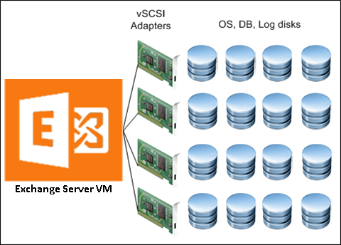
Virtual SCSI Adapters
VMware provides two commonly used virtual SCSI adapters for Windows Server 2019: LSI Logic SAS and VMware Paravirtual SCSI (PVSCSI). The default adapter when creating new VMs running Windows on vSphere is LSI Logic SAS, and this adapter can satisfy the requirements of most workloads with no additional drivers. A VM can be configured with up to four virtual SCSI adapters.
The LSI Logic SAS type adapter can accommodate up to 15 storage devices (volumes) per controller, for a total of 60 volumes per VM. The LSI Logic SAS controller is recommended for the operating system volumes and for workloads which do not require a lot of IOPS for their operations.
Exchange Server 2019 continues to reduce the amount of I/O generated to access mailbox data. In addition, Exchange Server 2019 now supports the use of larger volumes to accommodate multiple Exchange Server databases per volumes. This improvement enables customers to fully leverage VMware’s increased datastore size (62TB) and to locate multiple Exchange Server mailbox database volumes (VMDKs) in large datastores, instead of creating multiple smaller datastores to satisfy the constrained volume size limits in previous versions of Exchange Server.
The Paravirtual SCSI adapter is a high-performance vSCSI adapter developed by VMware to provide optimal performance for virtualized business-critical applications. The advantage of the PVSCSI adapter is that the added performance is delivered while minimizing the use of hypervisor CPU resources. This leads to lower hypervisor overhead required to run storage I/O-intensive applications.
PVSCSI also supports a larger number of volumes-per-controller (64), enabling customers to create up to 256 volumes per VM. VMware recommends that customers limit the number of PVSCSI controllers attached to a single VM to three if they intend to take advantage of this increased volumes-per-controller feature. Based on this recommendation, customers should expect to be able to able to allocate a maximum of 192 PVSCSI-connected volumes per VM.
In environments supporting thousands of users per mailbox server, VMware recommends that customers use the PVSCSI controllers for all Exchange Server mailbox database and transaction logs volumes. To ensure optimal utilization, VMware recommends that customers allocate as many PVSCSI controllers as possible in these environments and ensure that all volumes attached to VM are evenly distributed across all allocated PVSCI controllers.
Figure 7. Storage Distribution with Multiple vSCSI Adapters
Virtual SCSI Queue Depth
Queue depth denotes the number of I/Os that can pass through a storage path at one time. All other I/Os beyond this number are queued until the path has more room to accommodate them. Because there are multiple points through which an I/O will pass from within a guest operating system before it reaches the physical storage device, customers should pay special attention to their storage configuration to avoid unnecessary and undesirable I/O queuing for their Exchange Server VMs.
When presenting storage to a VM, the virtual disk is connected to one virtual SCSI controller. Each SCSI controller has a finite (and configurable) queue depth, which varies among the virtual SCSI controller types available in vSphere.
The PVSCSI controller is the optimal SCSI controller for an I/O-intensive application on vSphere. This controller has a queue depth of 64 (per device) and 254 (per controller) by default (double the size of an LSI Logic SAS controller). The PVSCSI controller’s per-device and per-controller queue depths can also be increased to 254 and 1024 respectively, providing even more increased I/O bandwidth for the virtualized workload.
Because of these increased performance and throughput benefits, VMware recommends that customers choose PVSCSI as the virtual SCSI controllers for their Exchange Server data, databases and logs volumes.
Note the following:
- Using PVSCSI for Exchange Server and Exchange DAG is officially supported on vSphere 7.0, although such configurations have been in common use since vSphere 5.1
- The PVSCSI driver is not native to the Windows operating system. Therefore, customers using PVSCSI controllers must keep the VMware Tools instances on their VMs updated on a regular basis. VMware Tools is the vehicle for delivering the PVSCSI drivers to the OS.
Figure 8. Common Points of Storage IO Queues
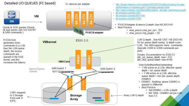
While increasing the default queue depth of a virtual SCSI controller can be beneficial to an Exchange Server VM, the configuration can also introduce unintended adverse effects in overall performance, if not done properly. VMware highly recommends that customers consult and work with the appropriate storage vendor’s support personnel to evaluate the impact of such changes and obtain recommendations for other adjustments that may be required to support the increase in queue depth of a virtual SCSI controller. See Large-scale workloads with intensive I/O patterns might require queue depths significantly greater than Paravirtual SCSI default values and Changing the queue depth for QLogic, Emulex, and Brocade HBAs for further information.
A Word on MetaCacheDatabase (MCDB)
One of the new features introduced in Microsoft Exchange Server 2019 is the MetaCacheDatabase (MCDB). MCDB is intended to allow DAG operations in Exchange Server 2019 to be accelerated by caching a portion of the data on SSD/Flash-based storage volumes.
Although this feature is currently recommended only for Microsoft Exchange Mailbox Servers running on physical hardware and configured to specifications prescribed in the Microsoft Preferred Architecture prescriptive guidance, customers looking to extend this feature to their virtualized Exchange Server 2019 DAG configuration in VMware vSphere environment can do so by presenting VMDKs created in SSDs/Flash disks to the VM and marking such disks as MediaType SSD within the guest operating system.
Exchange Server 2019 on All-Flash Storage Array
As all-flash storage is gaining increasing popularity in corporate data centers, many are examining the value of deploying Exchange Server on all-flash storage arrays. Exchange Server is generally perceived as a demanding workload in terms of capacity but is relatively less demanding from a performance perspective as compared to other database workloads. All-flash storage arrays are viewed as more expensive than traditional storage arrays when it comes to physical capacity cost-per-GB. Why would customers be interested in an all-flash storage option for Exchange Server 2019?
While many are well aware of the performance benefits of all-flash storage, the latest generation of all-flash storage also offers:
- Built-in data services, such as, always-on thin provisioning, inline data deduplication, and inline data compression that provide compelling data reduction ratio
- Flash-optimized data protection that replaces traditional RAID methodologies and simplifies Exchange Server sizing and capacity planning efforts while minimizing protection overhead and performance penalty
- Instant space efficient copies via Volume Shadow Service (VSS) integration that significantly increases efficiency and operational agility for DAGs and can be used for local data protection and potentially replace lagged copies
Exchange Server administrators are constantly facing a number of challenges when upgrading:
- The architecture for Exchange Server is rigid by nature; the design is intended to be built once and maintained with minor changes until decommission. Exchange Server admins are tasked with predicting projected mailbox growth and usage patterns for the upcoming four to five-year period. Storage is over-provisioned to avoid the potentially costlier mistake of under-sizing. The nature of SSD allows modern all-flash vendors to support 100% storage-on-demand with always-on thin provisioning and no performance impact. The initial acquisition cost of storage is significantly driven down.
- Exchange Server has long ago moved away from single instance storage. Exchange Server DAGs consume between 2x and 6x the capacity required to store a production copy of databases. Most companies report that capacity requirements have multiplied by a factor of 6x after migrating from Exchange Server 2003/2007 to version 2010/2013. Exchange Server data that used to consume 12TB of space in an Exchange Server 2003 single-copy cluster, now consumes 72TB in a three-copy DAG. With the right all-flash storage, initial database copies can be reduced in capacity. Passive DAG copies can be created in seconds via VSS integrated copy technology and consume no additional space.
- Distribution Groups (DLs) is a de facto method for transmitting messages within organizations. Coupled with the fact that nearly 70% of all email messages contain attachments and every attachment is stored repeatedly in every DL member's inbox, mailboxes and mailbox databases are larger than ever before. Massive opportunities exist to increase storage efficiency with all-flash storage solutions that offer inline data deduplication and compression.
- Many organizations are forced to run their Exchange Server in online mode for several reasons, including virtual desktop infrastructure (VDI), security and governance (cannot use OSTs), workflow applications (cannot tolerate cached versions of mailbox items), and HIPPA regulations. Online mode increases the I/O requirements compared to cached mode by 270%. Performance can still be a critical consideration for Exchange Server deployment in many cases.
During a study of Exchange Server on EMC XtremIO, EMC found incredible efficiencies resulting in a reduction of the total disk required to manage an Exchange Server environment. These efficiencies led to significant cost-reduction opportunities over a five-year period. Further to the point, the total cost of ownership (TCO) of XtremIO mirrored that of alternative solutions including VNX and Microsoft preferred architecture, while offering tangibly improved performance and simpler storage management.
Figure 9. Cost of Ownership Comparison
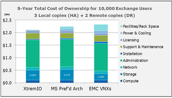
The TCO study above is based on a straw man configuration of 10,000 seats and 2GB average mailbox size, with 150 messages sent and received per user, per day. For the purposes of the study, TCO includes all aspects of installing, managing, cooling, supporting, and paying for facilities costs typically found in most TCO models. Figure 9 above shows three Exchange 2010 implementations based on three different storage devices. All other aspects of the Exchange implementation are held constant (i.e., number of servers, Ethernet ports, admins, mailboxes, databases and database copies), with the only variations occurring relative to storage and its associated costs (i.e., maintenance, installation, facilities costs, power and cooling).
Reviewing the results, all three storage configurations incurred average mailbox costs within 25 cents of each other, with hardware costs potentially bringing these further in line. Prices used in this TCO study are the typical of those found in the open marketplace and do not include special discounts, list prices, or one-time offers.
The data-reduction ratio for EMC XtremIO, resulting from the combination of thin provisioning, deduplication, compression, and space-efficient copies with XtremIO Virtual Copies, was 7:1. The data reduction ratio increases as more mailboxes and DAG copies are placed onto the array, making XtremIO even more attractive for larger deployments.
Figure 10 - Data Reduction Ratio on XtremIO
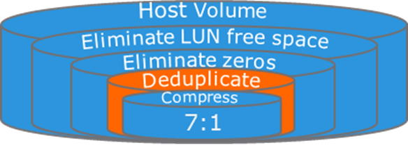
All-flash array is typically more expensive than traditional storage array or DAS. As customers move past the initial hardware acquisition cost and begin to consider the efficiencies and operational agility of all-flash array, they’re more likely to realize its value as a compelling storage platform for Exchange deployments and its efficient TCO.
References:
Using VMware vSAN for Microsoft Exchange Server Workloads
VMware vSAN (vSAN) is the VMware software-defined storage solution for hyperconverged infrastructure (HCI), a software-driven architecture that delivers tightly integrated computing, networking, and highly resilient shared storage from x86 servers. Like vSphere, vSAN provides users the flexibility, and control to choose from a wide range of hardware options; and easily deploy and manage them for a variety of IT workloads and use cases.
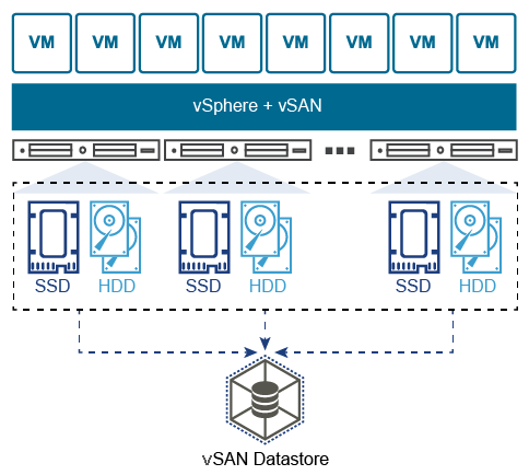
vSAN can be configured as a hybrid or an all-flash storage. In a hybrid disk architecture, vSAN leverages flash-based devices (SAS/SATA SSD or NVMe SSD) for cache, and magnetic disks for capacity. In an all-flash vSAN architecture, vSAN can use flash-based devices for both cache tier, and capacity tier.
vSAN is distributed object-based storage that leverages the Storage Policy Based Management (SPBM) vSphere feature to deliver centrally managed infrastructure, application-centric storage services, and storage capabilities at a granular level. Administrators can specify storage attributes, such as capacity, performance, and availability as a policy on a per-object (such as an individual VMDK) level or can also apply to all objects within a virtual machine.
Hosting virtualized Microsoft Exchange Server workloads on VMware vSAN storage requires the same careful considerations for the underlying storage subsystem, exactly in the same manner as it would be for a physical storage array. Before making design decisions, ensure that the type of workload to be hosted is analyzed, and the performance, availability, and capacity requirements are collected. It is particularly important to ensure that you input the correct storage information when using the “Exchange Calculator” for your sizing exercise.
While the overall disk, partition and volume sizing decisions will be largely driven by a combination of the prescriptions dictated by the “Calculator”, the number of mailbox servers and databases, as well as the volumes and characteristics of the emails sent, received and stored, VMware is providing the following recommendations to help customers select the right vSAN configuration which will best ensure the most optimal performance, resilience and support for the various database and logs read/write/search operations expected in the environment.
Hybrid vs. All-Flash vSAN for Exchange Server
Hybrid vSAN is still a viable option for both cost and performance reasons for Microsoft Exchange. Depending on your Exchange Server Calculator results a Hybrid vSAN might be adequate. However, all considerations posted below should not be applied to any infrastructure where performance is the primary goal.
- Hybrid vSAN might satisfy the requirements for such workloads if the following is considered:
- The use of multiple disk groups is strongly recommended to increase the system throughput
- It is important to have enough space in the caching tier. The general recommendation of the SSD as the caching tier for each host is to be at least 10 percent of the total storage capacity. However, the recommended SSD size should be at least two times that of the working data set.
- Select the appropriate SSD class to support planned IOPS. A SAS SSD device will perform better than a SATA SSD device in most cases, and has a bigger queue depth
- All-flash vSAN might yield satisfactory performance with better space savings that hybrid vSAN, at a lower cost with the following settings:
For the Mailbox database disks, using RAID 5/6 erasure coding to reduce space usage might be a choice, if space/cost savings are desired. The virtual disks for the logs should still be placed on the VMDK configured with RAID 1 policy. It is important to note that this recommendation applies to workloads that do not require high performance, and space savings are desired.
General vSAN for Exchange Server Recommendations
The following set of recommendations are applicable to all versions of Microsoft Exchange Server when hosted on vSAN:
- A minimum of 4 hosts is recommended.
- A minimum of 10Gb networking is required, both host networking and physical switch. The NIC must listed on the HCL. The switch must be a non-blocking high buffer count switch.
- A minimum of 2 disk groups per host is recommended.
- vSAN Services to Enable for a virtualized Microsoft Exchange Server infrastructure:
- vSAN Encryption – if required.
- Configure and set SPBM for Exchange Server data.
- Failures to tolerate: Use the vSAN Default Storage Policy’s “Failures to Tolerate” of 1 for Transaction Logs and Database VMDKs.
- Number of disk stripes per object: The default policy of stripe width (1) is sufficient and optimal for most Exchange Server infrastructure.
- If you are trying to increase performance consider spreading the data between multiple VMDKs attached to multiple PVSCSI controllers. Check the recommended virtual disk design in the previous section of this document.
- Use separate VMDKSs for Logs and Databases
For exceptional cases where even more performance and availability are highly important, consider the following:
- Use an All-flash vSAN deployment.
- Consider using at least SAS SSD devices. A SAS SSD device has a larger queue depth and will perform better than a SATA SSD device in most cases.
- RAID 1 mirroring and at least 1 failure to tolerate (FTT) for both database and logs VMDKs.
- While additional availability requirements might tempt Exchange Server Administrators and Architects to want to increase the FTT, Vmware recommends that customers consider increasing the number of DAG copies on the Exchange Server side instead.
- NOTE: More DAG copies require more storage
- If a multi-site availability is required, the “vSAN Stretched Cluster” configuration may be used to increase the data availability across datacentres
- Consider using high performance networking devices for the vSAN backend network. Use at least 10 Gbit switches with enough buffers to sustain high throughput.
Networking Configuration Guidelines
This section covers design guidelines for the virtual networking environment and provides configuration examples at the ESXi host level for Exchange Server 2019 installations.
Note The examples do not reflect design requirements and do not cover all possible Exchange network design scenarios.
Virtual Networking Concepts
The virtual networking layer comprises the virtual network devices through which VMs and the ESXi host interface with the rest of the network and users. In addition, ESXi hosts use the virtual networking layer to communicate with iSCSI SANs and NAS storage.
The virtual networking layer includes virtual network adapters and the virtual switches. Virtual switches are the key networking components in vSphere. The following figure provides an overview of virtual networking in vSphere.
Figure 12. vSphere Virtual Networking Overview
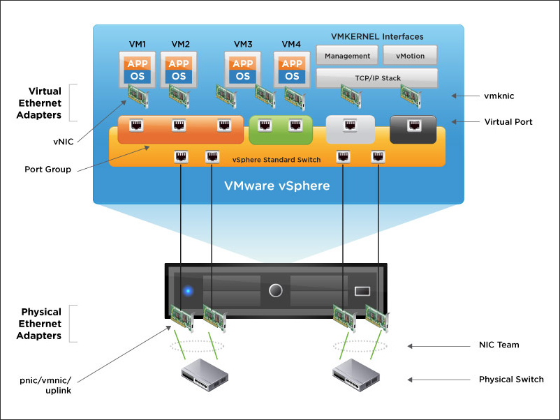
As shown in the preceding figure, the following components make up the virtual network:
- Physical switch – vSphere host-facing edge of the physical local area network
- NIC team – group of physical NICs connected to the same physical/logical networks to provide redundancy
- Physical network interface (pnic/vmnic/uplink) – provides connectivity between the ESXi host and the local area network
- vSphere switch (standard and distributed) – the virtual switch is created in software and provides connectivity between VMs. Virtual switches must uplink to a physical NIC (also known as vmnic) to provide VMs with connectivity to the LAN, otherwise VM traffic is contained within the virtual switch.
- Port group – used to create a logical boundary within a virtual switch. This boundary can provide VLAN segmentation when 802.1q trunking is passed from the physical switch, or it can create a boundary for policy settings.
- Virtual NIC (vNIC) – provides connectivity between the VM and the virtual switch
- VMkernel (vmknic) – interface for hypervisor functions, such as connectivity for NFS, iSCSI, vSphere vMotion, and VMware vSphere Fault Tolerance logging
- Virtual port – provides connectivity between a vmknic and a virtual switch
Virtual Networking Best Practices
The standard VMware networking best practices apply to running Exchange on vSphere:
- The choice between standard and distributed switches should be made outside of the Exchange design. Standard switches provide a straightforward configuration on a per-host level. For reduced management overhead and increased functionality, the distributed virtual switch should be considered. Both virtual switch types provide the functionality needed by Exchange Server 2019.
- Traffic types should be separated to keep like traffic contained to designated networks. vSphere can use separate interfaces for management, vSphere vMotion, and network-based storage traffic. Additional interfaces can be used for VM traffic. Within VMs, different interfaces can be used to keep certain traffic separated. Use 802.1q VLAN tagging and virtual switch port groups to logically separate traffic. Use separate physical interfaces and dedicated port groups or virtual switches to physically separate traffic. This is shown in Figure 13.
- Leverage network interface-teaming capabilities to provide redundant uplinks for virtual switches. To use this capability, assign at least two physical network interfaces per virtual switch.
- Use the VMXNET3 network adapter – a paravirtualized network device that provides better throughput with reduced hypervisor CPU utilization. It is imperative that customers regularly update VMware Tools on VMs using VMXNet3 virtual adapters.
- Previous Microsoft clustering configuration guidance recommends that, for Exchange Server 2019 VMs participating in a DAG, customers should configure at least two virtual network interfaces, connected to different VLANs or networks. These interfaces provide access for client access and replication traffic. This guidance is no longer operative in recent versions of Windows clustering. Consequently, VMware recommends that customers adhere to the latest guidance from Microsoft regarding whether or not to separate client-access traffic and replication traffic onto different network adapters.
- Where possible, consider enabling jumbo frames on the virtual switches where vSphere vMotion traffic is enabled. This is to improve vSphere vMotion operations, especially for Exchange Server VMs participating in a DAG configuration. Jumbo frames must also be enabled on physical network infrastructure before making this configuration on the virtual switches.
- Follow the guidelines on guest operating system networking considerations and hardware networking consideration in Performance Best Practices for VMware vSphere 7.0.
Sample Exchange Virtual Network Configuration
Because of the flexibility of virtual networking, the topology can take many different forms. There is no single recommended practice because each provides its own sets of benefits. The following figure shows two examples of a host-level configuration based on the most common configurations, which are single and multiple virtual switches.
Figure 13. Sample Virtual Network Configuration
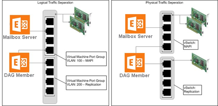
It’s not required to separate client access and DAG replication traffic onto different network adapters. However, this configuration is still a general practice among many customers. Although VMware encourages customers to validate this configuration with their Microsoft support representatives, the diagram depicts a configuration for completeness.
In the vSphere environment, traffic separation can be established using virtual or physical networks. The figure above provides examples of the following two scenarios:
- The scenario on the left depicts an ESXi host with two network interfaces, teamed for redundancy and using virtual networks and port groups to provide traffic separation for client access and DAG replication traffic. This scenario can also utilize VMware vSphere Network I/O Control for dynamic traffic prioritization.
- The scenario on the right depicts an ESXi host with multiple network interfaces. Physical traffic separation is accomplished by allocating two vmnics on one network to a virtual switch. These vmnics are teamed and dedicated to client access network traffic. DAG replication traffic uses a third vmnic on a separate virtual switch.
In both scenarios, the DAG member VM is connected to both networks, according to best practice.
Power Management
The vSphere ESXi hypervisor provides a high-performance, competitive platform that effectively runs many tier one application workloads in VMs. By default, ESXi has been heavily tuned for driving high I/O throughput efficiently by utilizing fewer CPU cycles and conserving power, as required by a wide range of workloads. However, many applications require I/O latency to be minimized, even at the expense of higher CPU utilization and greater power consumption.
VMware defines latency-sensitive applications as workloads that require optimizing for a few microseconds to a few tens of microseconds end-to-end latencies. This does not apply to applications or workloads in the hundreds of microseconds to tens of milliseconds end-to-end-latencies. Microsoft Exchange Server is not considered a latency sensitive application. However, given the adverse impact of incorrect power settings in a Windows operating system, customers should pay special attention to power management on an Exchange Server VM on the vSphere platform. See Best Practices for Performance Tuning of Latency-Sensitive Workloads in vSphere VMs and the Running Network Latency Sensitive Workloads section of Performance Best Practices for VMware vSphere 7.0.
NOTE: Keep in mind that many of the prescriptions provided in these documents do not apply to Exchange Server workloads and might induce suboptimal performance if applied to Exchange Server VMs. VMware recommends that customers ensure they thoroughly test implementations of these recommendations in non-production environments.
Server hardware and operating systems are engineered to minimize power consumption. Both the Windows operating system and vSphere ESXi hypervisor favor minimized power consumption over performance. Modern vSphere versions (including vSphere 7.0) default to a balanced power scheme. For critical applications such as Exchange Server, the default power scheme in vSphere 7.0 is not recommended.
Figure 14. Default ESXi 6.x Power-Management Setting
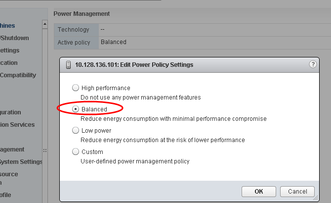
There are three distinct areas of power management in a vSphere hypervisor virtual environment: server hardware, hypervisor and guest OS. The following section provides power management and power setting recommendations for each of these areas.
Server Hardware BIOS Settings
Most servers with new Intel and AMD processors provide power-savings features that use several techniques to dynamically detect the load on a system and put various components of the server, including the CPU, chipsets and peripheral devices, into low-power states when the system is mostly idle. Hardware-level power management adds latency to the path where an idle system (in one of several power-savings modes) responds to an external event. Consequently, VMware recommends the following BIOS-level power-management settings for Exchange Server 2019 on vSphere:
- Set Power Management (or its vendor-specific equivalent label) to OS controlled. This will enable the ESXi hypervisor to make the most judicious power management decision based on actual utilization and the condition of the running VMs.
- Disable all processor C-states (including the C1E halt State). These enhanced power-management schemes can introduce memory latency and suboptimal CPU state changes (Halt-to-Full), resulting in reduced performance for the VM.
- Enable Turbo Boost, if available.
ESXi Host Power Settings
ESXi can take advantage of several power management features that the host hardware provides to adjust the trade-off between performance and power use. It’s possible to control the way in which ESXi uses these features by selecting a power-management policy.
In general, selecting a high-performance policy provides more absolute performance, but at lower efficiency (performance-per-watt). Lower-power policies provide lower absolute performance, but at higher efficiency. ESXi provides five power-management policies. If the host does not support power management, or if the BIOS settings specify that the host operating system is not allowed to manage power, only the Not Supported policy is available.
Table 3. CPU Power Management Policies
| Power Management Policy | Description |
| High Performance | The VMkernel detects certain power-management features but will not use them unless the BIOS requests them for power-capping or thermal events. This is the recommended power policy for an Exchange Server running on ESXi. |
| Balanced (Default) | The VMkernel uses the available power-management features conservatively to reduce host energy consumption with minimal compromise to performance. |
| Low Power | The VMkernel aggressively uses available power-management features to reduce host energy consumption at the risk of lower performance. |
| Custom | The VMkernel bases its power-management policy on the values of several advanced configuration parameters. These parameters can be set in the vSphere Web Client Advanced Settings dialog box. |
| Not supported | The host does not support any power-management features or power management is not enabled in the BIOS. |
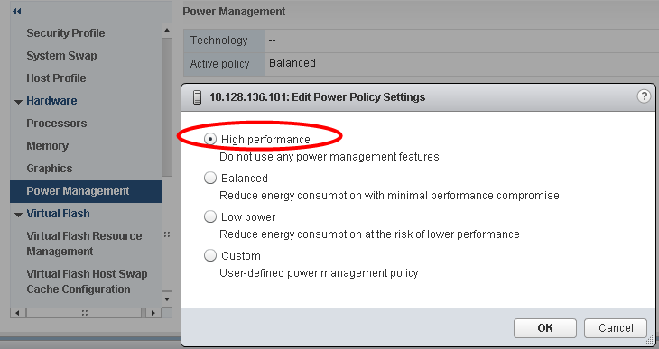
VMware recommends setting the high-performance power policy for ESXi hosts in an infrastructure hosting Microsoft Exchange Server VMs. It’s possible to select a policy for a host using the vSphere Web Client. If a policy is not selected, ESXi uses balanced by default.
Figure 15. Recommended ESXi Host Power-Management Setting
When a CPU runs at lower frequency, it can also run at lower voltage, which saves power. This type of power management is called dynamic voltage and frequency scaling (DVFS). ESXi attempts to adjust CPU frequencies so that VM performance is not affected.
When a CPU is idle, ESXi can take advantage of deep halt states (known as C-states). The deeper the C-state, the less power the CPU uses, but the longer it takes for the CPU to resume running. When a CPU becomes idle, ESXi applies an algorithm to predict how long it will be in an idle state and chooses an appropriate C-state to enter. In power-management policies that do not use deep C-states, ESXi uses only the shallowest halt state (C1) for idle CPUs.
Windows Guest Power Settings
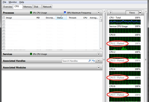
The default power-policy option in modern Windows operating systems is balanced. This configuration allows the Windows OS to save power consumption by periodically throttling power to the CPU and turning off devices such as the network cards in the guest when Windows determines that they are idle or unused. This capability is inefficient for an Exchange Server workload due to the latency and disruption introduced by the act of powering off and powering on CPUs and devices. Allowing Windows to throttle CPUs can result in what Microsoft describes as core-parking. See the Power Management section of Troubleshooting High CPU Utilization Issues in Exchange 2013 for more information.
Figure 16. Windows CPU Core Parking
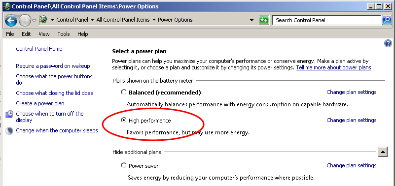
Microsoft recommends the high-performance power-management policy for applications requiring stability and performance. VMware supports this recommendation and encourages customers to incorporate it into their server tuning and administration practices for virtualized Exchange Server VMs.
Figure 17. Recommended Windows Guest Power Scheme
Using vSphere Technologies with Exchange Server 2019
This rest of this section explores the technologies and features available in a VMware vSphere infrastructure, which complement and enhance Microsoft Exchange Server’s native high availability, recovery and resilience options – namely vSphere HA, vSphere Distributed Resource Scheduler, vSphere vMotion and the VMware Site Recovery Manager. This also includes proven best practices for using these technologies with critical applications such as Exchange Server 2019.
Although all Exchange Server roles have been capable of taking advantage of these advanced vSphere features, official support by Microsoft for their use with DAG members was not available until Exchange 2010 SP1. Exchange Server 2019 was released with the same support for these features, validating the continued effort by both VMware and Microsoft to provide support for the features that customers believe are valuable for virtualized Exchange Server environments.
Overview of vSphere Technologies
VMware vSphere includes a number of features and technologies which considerably complement and enhance the native resilience, availability, portability, mobility and recoverability features of virtualized guest operating systems and the workloads they host.
The following section discusses these features and their usage and suitability for Microsoft Exchange Server workloads.
vSphere HA
With vSphere HA, Exchange Server VMs on a failed ESXi host can be restarted on another ESXi host. This feature provides a cost-effective failover alternative to third-party clustering and replication solutions.
When using vSphere HA, users should be aware of the following:
- vSphere HA handles ESXi host hardware failure and does not monitor the status of the Exchange services. These must be monitored separately.
- A vSphere HA heartbeat is sent using the vSphere VMkernel network, so optimal uplink bandwidth and redundancy in this network are strongly recommended.
- Allowing two nodes from the same DAG to run on the same ESXi host for an extended period is not recommended when using symmetrical mailbox database distribution. This condition will create a single-point-of-failure scenario if the two nodes have the only copies of one or more mailbox databases. DRS anti-affinity or guest-to-host affinity rules should be used to mitigate the risk of running active and passive mailbox databases on the same ESXi host.
vSphere vMotion
vSphere vMotion technology enables the migration of VMs from one ESXi host to another without service interruption. This migration allows movement of Exchange Server VMs from a heavily loaded ESXi host to one that is lightly loaded or to offload them to allow for hardware maintenance without any downtime.
Support for using vSphere vMotion with Exchange VMs with Exchange DAG members has existed since early 2011, when Exchange 2010 SP1 was released. Although a well-designed and purpose-built vSphere infrastructure can provide seamless migration of a running Microsoft Exchange Server VM without interfering with Exchange Server operations (e.g. client connectivity and service availability), VMware encourages customers to pay special attention to specific configuration options which, if left unattended, could impede successful vMotion operation on Exchange Server workloads in the vSphere environment.
One of the most common challenges when performing a vMotion operation on clustered Exchange Mailbox Server (using DAG) is the potential to trigger unintended database failover during the vMotion operation. This can occur under the following conditions:
- Resource constraints within the vSphere cluster, which makes it difficult for the vMotion operation to complete on time, as vSphere tries to find enough compute resources to accommodate the migrated VM on the target host
- Network congestion or constraints – a vMotion operation copies the state of a VM over the network. If there is no adequate network throughput, the copy operation will take longer to complete. The operation could also be abandoned midway if it is determined that the operation cannot be completed within a reasonable time.
Even under ideal conditions, the heavy load of Exchange workloads and memory usage can cause a vSphere vMotion operation to trigger a database failover. Database failovers are not necessarily a problem if the environment is designed to properly distribute the load and can help to validate the cluster health by activating databases that might normally go for weeks or months without accepting a user load. However, many administrators prefer that database activations be a planned activity, or only done in the case of a failure. For this reason, VMware has studied the effect of vSphere vMotion on Exchange DAG members and provided the following best practice recommendations:
Cluster Heartbeat Settings
Exchange Server’s DAG relies on the Windows Server Failover Clustering (WSFC) Service. In previous versions of WSFC, each clustered Exchange Server node exchanges heartbeat packets with its partners every second. If the node does not receive a response from any partner after five consecutive probes, the probing node considers the partner to be non-responsive (unavailable). The WSFC service on the probing node then initiates corrective actions, including taking ownership of clustered resources previously owned by the non-responsive partner.
A clustered node considers its partner unavailable if it is unable to exchange heartbeat packets with that partner after five attempts (five seconds), which triggers actions necessary to provide continued availability of the resources located on that partner. This happens when there is an unintended and unplanned cluster resource failover.
An aggressive cluster failover threshold can be problematic and disruptive. For example, a failover might not have been required because the non-responsiveness was a transient issue that went away after six seconds.
During a vSphere vMotion operation, a VMs memory pages are gradually copied from its current parent host to its target parent host and the VM is subsequently switched over to the target host. During this copy and transition procedure, the VM is quiesced (VMware refers to this as stunning). Under normal operating conditions, the stun period is very brief and not noticeable. However, the quiescing period might last longer than the five-second threshold under some operating conditions, including the following:
- Size of the VM (CPU and RAM)
- Current outstanding operations, threads, and processes on the VM
- Total CPU subscription ratio in the vSphere cluster
- Network bandwidth or congestion state
The net effect of a stun operation is that the stunned VM is unable to exchange heartbeat for the duration of the stun operation. If this lasts longer than five seconds and the VM is in a cluster relationship, then its cluster partners consider it unavailable.
This behavior is not peculiar to vSphere vMotion or even virtualization in general. If a backup solution takes VSS-based snapshots of the server, it is also likely quiescing the server.
This is a known behavior. See Tuning Failover Cluster Network Thresholds for a detailed discussion that includes avoiding an unintended cluster failover incident (and its associated disruptive effects) when performing a vSphere vMotion operation on a DAG node. There are several configuration options described in the following sections that can be used to overcome these disruptive effects.
Changes in Windows Server 2019 WSFC Thresholds
The phenomenon described in the preceding section informed VMware’s previous recommendations that customer should actively adjust the threshold at which WSFC triggers a resource failover during a period of fleeting network outage.
Windows Server 2019 defaults conform with VMware’s historical recommendations, as seen in the image below:
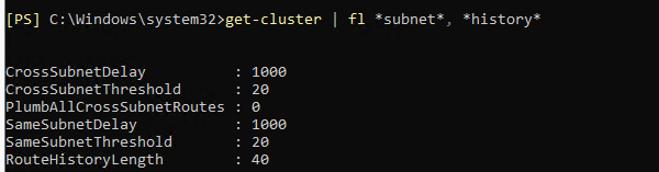
It is, therefore, no longer necessary for customers to adjust these settings as VMware finds the default values in Windows Server 2019 to be adequate and sufficient.
Multiple vSphere vMotion Interfaces
Database failover due to vSphere vMotion operations can be mitigated by using multiple dedicated vSphere vMotion network interfaces. In most cases, the interfaces that are used for vSphere vMotion are also used for management traffic. Because management traffic is relatively light, this does not add significant overhead.
vSphere provides the ability to use multiple vmnic interfaces for vSphere vMotion traffic to effectively load-balance the vSphere vMotion traffic. Testing has shown up to a 25% increase in throughput achieved when multiple vSphere vMotion interfaces are used. In the test case with two 2GBps interfaces configured for vSphere vMotion and no cluster heartbeat modifications, vSphere vMotion operations succeeded with no database failover.
Enabling multiple interfaces for vSphere vMotion requires configuring multiple VMkernel ports on different port groups. Each port group is assigned multiple vmnic interfaces as either active or standby. See Multiple-NIC vMotion in vSphere for detailed configuration procedures.
Before deciding to use this configuration option, see vMotion migrations fail when using multiple VMkernel ports for vMotion in different IP subnets.
Enable Jumbo Frames for vSphere vMotion Interfaces
Standard Ethernet frames are limited to a length of approximately 1500 bytes. Jumbo frames can contain a payload of up to 9000 bytes. Support for jumbo frames on VMkernel ports was added to vSphere 4.0 for both ESX and ESXi. This added feature means that large frames can be used for all VMkernel traffic, including vSphere vMotion.
Using jumbo frames reduces the processing overhead to provide the best possible performance by reducing the number of frames that must be generated and transmitted by the system. During testing, VMware tested vSphere vMotion migration of DAG nodes with and without jumbo frames enabled. Results showed that, with jumbo frames enabled for all VMkernel ports and on the VMware vNetwork Distributed Switch, vSphere vMotion migrations of DAG member VMs were completed successfully. During these migrations, no database failovers occurred, and there was no need to modify the cluster heartbeat setting.
The use of jumbo frames requires that all network hops between the vSphere hosts support the larger frame size. This includes the systems and all network equipment in between. Switches that do not support (or are not configured to accept) large frames will drop them. Routers and Layer 3 switches might fragment the large frames into smaller frames that must then be reassembled, which can cause both performance degradation and a pronounced incidence of unintended database failovers during a vSphere vMotion operation. Do not enable jumbo frames within a vSphere infrastructure unless the underlying physical network devices are configured to support this setting.
A quick way to verify this is by running the following command from one ESXi host to another and examining the returned output for errors or reports of fragmentation:
vmkping -s 8972 -d Target-Host-IP-address
vSphere Distributed Resource Scheduler
Distributed resource-scheduling provides active load-balancing of VM workloads within a vSphere cluster. Aside from the active monitoring and load-balancing functions, DRS provides the following features:
- VM placement during power-on, based on resource requirements and availability
- VM evacuation during ESXi host maintenance mode
- VM and host groups for grouping like objects
- Rules to keep VMs together or apart and on or off of a set of hosts
DRS helps make a virtualized Exchange Server 2019 environment more agile. The following sections provide recommendations for using DRS with Exchange Server 2019.
vMotion and DRS Together
DRS takes vSphere vMotion a step further by adding an intelligent scheduler. DRS allows you to set resource assignment policies that reflect business needs. DRS does the calculations and automatically handles the details of physical resource assignments. It dynamically monitors the workload of the running VMs and the resource utilization of the physical servers within a vSphere cluster.
vSphere vMotion and DRS perform best under the following conditions:
- The source and target ESXi hosts must be connected to the same network and the same shared storage
- A dedicated 10-gigabit (or higher) network for vSphere vMotion is recommended
- The vSphere vMotion or DRS target host must have enough resources to accommodate the VM that will be migrated
- The VM must not have physical devices such as a CD-ROM or floppy disk attached during the vSphere vMotion operation
- The source and destination hosts must have compatible CPU models, otherwise migration with vSphere vMotion fails. If the vSphere cluster contains hosts with different CPU generations, then Enhanced vSphere vMotion Compatibility (EVC) must be enabled in the cluster to allow vSphere vMotion operations to succeed. See EVC and CPU Compatibility FAQ for more information on EVC.
- VMs with smaller memory sizes are better candidates for migration than larger ones
- Persistent resource over-commitment in a vSphere cluster can impede the efficiency of vSphere vMotion operations
Enable DRS in Fully Automated Mode
DRS provides the following levels of automation:
- Manual – migration recommendations are provided by DRS. No migrations are performed by DRS.
- Partially automated – VMs are automatically placed on hosts during power-on, migration recommendations are provided by DRS, and no migrations are performed by DRS
- Fully automated – VMs are automatically placed on hosts during power-on and are automatically migrated between hosts to optimize resource usage
When designed according to VMware recommendations, vSphere clusters that have been purpose-built for Exchange Server 2019 possess sufficient resources and do not experience many DRS migrations. However, when an ESXi host is placed in maintenance mode, DRS makes recommendations on placement of VMs running on that host. To leverage automatic host-evacuation, the DRS automation level must be set to Fully Automated.
If the vSphere cluster hosting Exchange Server 2019 is a shared environment, DRS in fully automated mode helps to maintain resource optimization among the multiple workloads.
Use Anti-Affinity Rules for Exchange Virtual Machines
DRS provides rules for keeping VMs apart or together on the same ESXi host or group of hosts. In an Exchange environment, the common use case for anti-affinity rules is to keep Exchange VMs with the same roles installed separated from each other.
Microsoft recommends symmetrically distributing mailbox databases among DAG members. Unlike traditional active/passive configurations, this design allows all DAG members to support active users as well as reserve a portion of compute power for failover capacity. In the case of failure of a single DAG member, all remaining members may take part in supporting the failed databases. It’s therefore recommended that no two members of the same DAG run on the same ESXi host for an extended period.
Figure 18. vSphere Distributed Resource Scheduler Anti-Affinity Rule
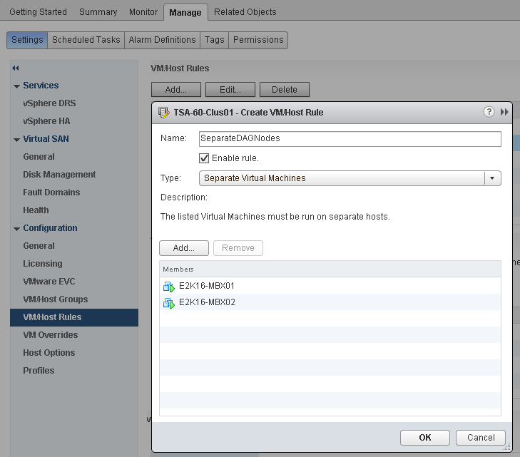
Anti-affinity rules enforce VM separation during power-on operations and vSphere vMotion migrations due to a DRS recommendation, including a host entering maintenance mode. Prior to vSphere 5.5, if a VM is enabled for vSphere HA and a host experiences a failure, vSphere HA may power-on a VM and violate a DRS anti-affinity rule, as vSphere HA does not inspect DRS rules during a recovery task. However, during the next DRS evaluation (every 5 minutes), the VM is migrated to fix the violation.
To avoid this condition when utilizing DRS with vSphere 5.5, VMware encourages customers to apply the following vSphere HA Advanced Configuration option to their vSphere Clusters:
das.respectVmVmAntiAffinityRules = TRUE
This setting instructs vSphere HA to inspect and respect vm-vm anti-affinity rules when restarting VMs after a host failure. The Exchange Server VMs separated by an anti-affinity will not be co-located on the same ESXi host.
Figure 19. HA Advanced Configuration Option for DRS Anti-Affinity Rules
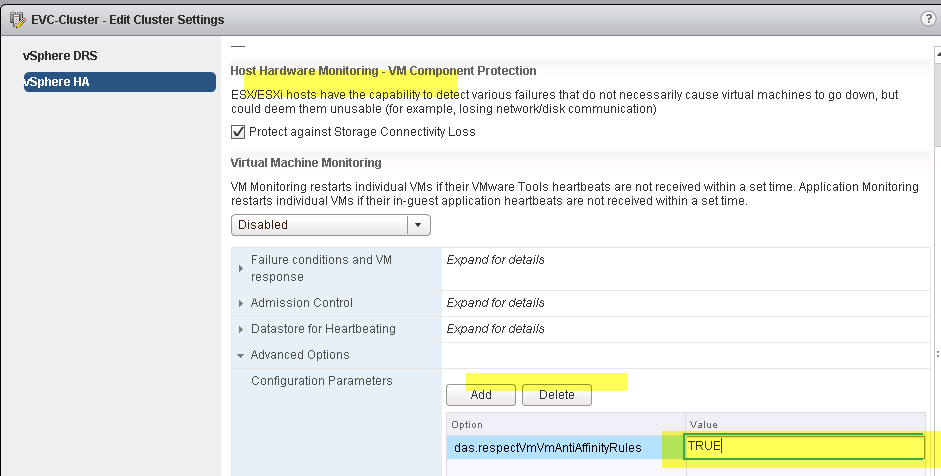
As shown in the following figure, vSphere 7.0 includes an improved, GUI-based configuration option to control the way in which vSphere HA responds to all DRS rules in a cluster. It is no longer required to configure the Advanced Configuration parameter manually.
Figure 20. Improved vSphere HA and DRS Interoperability in vSphere 7.0
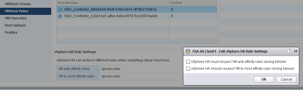
DRS Groups and Group-Based Rules
Defining DRS groups helps enforce VM placement in a way that is not possible with affinity and anti-affinity rules only. Host groups can contain hosts licensed to run an application or hosts in a blade chassis or rack. VM groups can contain VMs with a similar purpose. With groups defined, the virtual machines to hosts-type rule is available for use. VMs to hosts rules can be created with four variations:
- VM group must run on hosts in group
- VM group should run on hosts in group
- VM group must not run on hosts in group
- VM group should not run on hosts in group
Must run on rules provide hard enforcement of VM placement. If a rule stipulates that a group of VM must run on a group of ESXi hosts, both DRS and vSphere HA obey these rules. If all hosts in the group are down, the VMs are unable to run on any other host in the vSphere cluster.
In the following figure, two VM groups and two host groups are defined. Two must run on rules, shown in the solid black ovals, keep the VMs in each group running on their respective host group. The VM in the middle is not tied to a group or a rule and might roam. In the case of a failure of all hosts in the group, all VMs bound to those hosts by a must run on rule stay offline until a host from that group is brought back online.
Figure 21. Must Run on Rule Example
![]()
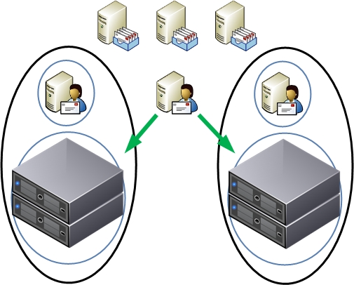
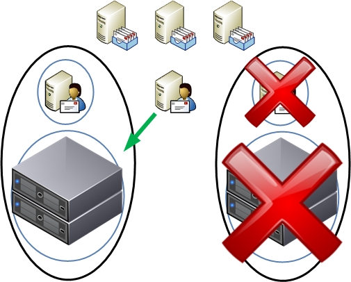
Should run on rules provide soft enforcement of VM placement. If a rule stipulates that a group of VMs should run on a group of ESXi hosts, those VMs will always be preferentially placed on hosts in the host group. They can still run on other hosts in the vSphere cluster outside of the host group, if needed (e.g., if all the hosts in the host group are unavailable or otherwise unsuitable for the VM).
In the following figure, two VM groups and two host groups are defined. Two should run on rules, shown in the broken green ovals, keep the VMs in each group running on their respective host group. The VM in the middle is not tied to a group or a rule and might roam. In the case of a failure of all hosts in the group, VMs bound to those hosts by a should run on rule can be brought back online by vSphere HA.
Figure 22. Should Run on Rule Example
![]()
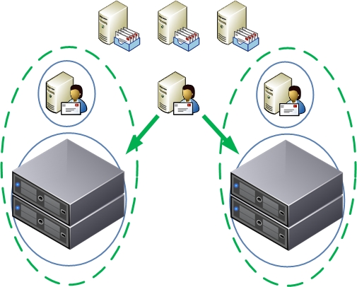
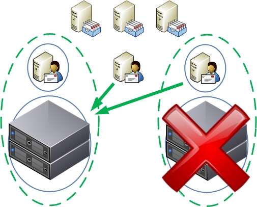
In an Exchange Server 2019 environment, VM-to-host rules can be used to provide soft or hard enforcement of VM placement. As an example, consider creating groups of ESXi hosts based on a failure domain, such as a blade chassis or server rack. Create two VM groups with each containing half of the Exchange Server VMs and create rules to link each VM group to a host group. In the case of a complete chassis or rack failure, any VMs that have failed can be powered back on by vSphere HA.
vSphere High Availability
By providing a higher level of availability than is possible out-of-the-box for most applications, vSphere HA has become the default HA solution for vSphere VMs. Regardless of operating system or application, vSphere HA can provide protection from ESXi host failures, guest operating system failures, and, with the help of third-party add-ons, application failures.
Exchange Server 2019 environments are built for high availability. Mailbox servers are deployed in DAGs for mailbox database high availability. Theoretically, this provides all of the availability required by an Exchange Server. However, in the case of a hardware failure, utilization of the remaining Exchange servers rises as new connections are established, and DAG protection is compromised as passive databases are activated. In a physical deployment, an administrator needs to address the problem quickly to restore availability levels and mitigate any further outages. This condition informs Microsoft’s recommendation of at least four DAG copies in a production Exchange Server infrastructure, increasing cost of ownership (e.g., storage, licensing) as well as administrative and management overhead. With a vSphere infrastructure, a hardware failure results in VMs being powered back on by vSphere HA, restoring availability levels quickly, and keeping utilization balanced. With increased availability, customers are able to reduce the number of DAG copies required to efficiently run their Exchange Server infrastructure. The following sections provide recommendations for using vSphere HA with Exchange Server 2019.
Admission Control
The amount of failover capacity provided by hosts in a vSphere cluster determines how many host failures can be tolerated. For example, in a four-host cluster, each host needs to reserve at least 25% of its resources to accommodate the workloads of one host in the event of a failure. Reserving this capacity is a manual task without admission control.
vSphere Admission Control allows administrators to define policies that are used by vCenter to manage failover capacity. How vCenter failover capacity is calculated and reserved is determined by the following policies:
- The number of host failures a cluster can tolerate
- A percentage of the cluster resources that are reserved as failover spare capacity
- Dedicated failover hosts
- Sizes of the VMs in the cluster
Surviving a physical host failure without compromising performance or availability is a major driver for virtualizing business-critical applications. By configuring admission control, VMware vCenter Server™ monitors utilization and manages failover capacity. To provide sufficient resources in the case of a hardware failure, or even during maintenance, enable and configure admission control.
For more information on admission control and the policies see vSphere HA Admission Control in the vSphere Availability Guide.
Along with ESXi host monitoring, vSphere HA can also provide monitoring at the VM level. VM monitoring can detect guest operating system failures and, with the help of third-party software, application failures. vSphere HA establishes a heartbeat with VMware Tools, installed within the guest operating system, and monitors this heartbeat. If heartbeat communication fails between VMware Tools and vSphere HA, a secondary check is made against network and storage I/O activity. If both network and storage I/O activity has halted, vSphere HA triggers a VM restart.
Users should enable VM monitoring if there is a desire to reduce downtime due to guest operating system failures that would otherwise require manual intervention. This monitoring feature cannot detect Exchange processes, database health or failures, however. It is, therefore, not a replacement for Exchange DAG.
Using vSphere HA with Database Availability Groups
In a physical environment, DAGs are often deployed with three or more database copies to protect from hardware and disk failures. In these environments, when a physical server or storage component fails, the DAG is still protected due to the multiple database copies. This comes at the expense of managing multiple database copies and other administrative overhead. Exchange environments built on vSphere are typically designed with two database copies and utilize vSphere HA and RAID to protect from hardware and storage failures. vSphere HA restarts a DAG member if the host on which it was running experiences a hardware failure or becomes otherwise unavailable. RAID protects databases from storage failure at the array level.
When enabling a vSphere cluster for HA with the intention of protecting DAG members, consider the following:
- Members of the same DAG should not reside on the same vSphere host for an extended period of time when databases are symmetrically distributed between members. Allowing two members to run on the same host for a short period of time (e.g., after a vSphere HA event), even if doing so may violate resource availability constraints and DRS rule, allows the Exchange server VM to become operational and for database replication and protection to resume quicker. DAG members should be separated as soon as operationally feasible (e.g., as soon as the ESXi host becomes available or additional capacity has been added to the vSphere cluster).
- To adequately protect from an extended server outage, vSphere clusters should be designed in an N+1 configuration, where N is the number of DAG members. If a hardware failure occurs causing vSphere HA to power on a failed DAG member, Exchange servers and DAG maintain the same levels of performance and protection as during normal runtime.
- Use anti-affinity rules to keep DAG members separated. vSphere HA might violate this rule during a power-on operation (one caused by a host failure), but DRS fixes the violation during the next interval. To eliminate the possibility of DAG members running on the same host (even for a short period), must not run on virtual machine to host anti-affinity rules must be used.
Exchange Performance on vSphere
Since 2006, VMware and its partners have used testing to successfully demonstrate the viability of running Exchange on the VMware infrastructure platform. This testing has been confirmed by organizations who have been deploying Exchange Server workloads since version 2003 in virtualized production environments and who now benefit from the considerable operational advantages and cost savings of deployment. The ease of virtualizing an Exchange Server infrastructure, and the demonstrable parity in performance, reliability, availability and recoverability of a virtualized Exchange Server workload, over the years have combined to dispel the fear that many organizations may have had about virtualizing Exchange Server.
As previously mentioned, improvements in Exchange Server 2019, and the unambiguous support statement by Microsoft, make the decision about virtualizing Exchange Server a less onerous one. Even customers who have not adopted the new normal Virtualize First policy can expect the same optimal performance and reliability they’ve experienced on their physical-hardware Exchange Server instances when making the decision to virtualize.
Server hardware compute resources continue to expand on a regular basis. It is now quite uncommon to purchase a modern server that has fewer than 48 CPUs and 512GB of RAM. These modern-class servers are unsuitable for directly running Exchange Server 2019, due to the technical limitations in compute resources addressable by Exchange Server. Since an Exchange Server has an upper limit of 256GB RAM and 2-socket, 48-core CPUs, directly installing Exchange Server not only becomes cost-ineffective, it can also induce performance degradation.
This makes virtualization the most optimal and cost-effective configuration option for Exchange Server 2019. Virtualization helps customers overcome these limitations by efficiently partitioning and maximizing compute resources and allocating them to the Exchange Server VMs as required, without inducing performance bottleneck.
Many enterprises have adopted virtualization as their default design choice for new workloads. This choice is logical for an Exchange Server infrastructure for the following reasons:
- The Exchange information store (the Managed Store) has been rewritten to further optimize resource consumption. This update to the managed Store has also led to further reduction in storage I/O requirements.
- Advances in server hardware such as multicore processors, higher memory density, and advances in storage technology are far outpacing the performance requirements for applications, including Exchange Server 2019. Virtualization becomes an effective way to leverage the full power of these systems.
- The advances in Exchange Server 2019 and server hardware technology have coincided with advances in vSphere. On vSphere 7.0, VMs support up to 24TB RAM and 768 vCPUs, both of which are significantly higher than the maximum recommended compute resources for a single Exchange Server. The question of whether or not virtualization can support the performance requirements of an Exchange server is, therefore, moot.
VMware conducts baseline performance testing of every release of Exchange Server in order to be able to understand compute requirements and provide the applicable guidance to VMware customers. Because of the continued improvements carried over into Exchange Server 2019 storage I/O requirements, our validation tests (using the Microsoft Jetstress tool) revealed that, even under the most strenuous conditions, storage is not a significant cause of performance bottleneck for Exchange Server 2019 if the storage architecture adheres to VMware’s recommended configuration practices.
With concerns over relative storage I/Os and performance eliminated, many more Exchange administrators are finding the flexibility, enhanced availability, and lower costs associated with virtualization very attractive in supporting an Exchange infrastructure.
Key Performance Considerations
A variety of factors can affect Exchange Server 2019 performance on vSphere, including processor and memory allocation to the guest VM, storage layout and design, VM placement, and high availability methods. The following are tips for achieving the best possible performance:
- Fully understand your organization’s business and technical requirements for implementing Exchange Server 2019.
- Fully understand the Exchange workload requirements.
- Although I/O is reduced in Exchange Server 2019 compared with prior versions of Exchange Server and Exchange 2010, there is still a requirement to provide adequate throughput and low latency. Dedicate physical storage for Exchange to avoid compromising I/O by having other workloads running on the same physical disks.
- Although Microsoft has not updated the Exchanger Server Roles Requirements Calculator tools for Exchange Server 2019, VMware strongly encourages customers to ensure that they use the correct version of the tool (when it becomes available) to obtain the appropriate configuration guidelines for their Exchange Server 2019 VMs. The two primary tools for sizing an Exchange Server implementation are as follows:
- Exchange Server Role Requirements Calculator – obtain the correct version of this tool for a sizing exercise. For example, using the Exchange Server 2016 version of the tool to size an Exchange Server 2019 implementation will result in sizing recommendations that induce a noticeable performance bottleneck.
- Some of the input parameters required by the Role Calculator can result in under or over-sizing if the supplied information is inaccurate. One of the most important of these parameters is what Microsoft describes as the megacycle. The megacycle is a computed value derived from the publicly published SPECInt Ratings Values of the processor architecture of a given physical server. Manually calculating the correct megacycle value to use in your sizing exercise is not trivial. To help overcome this challenge, Microsoft has provided the Exchange Processor Query Tool, which automates retrieval of the appropriate rating value for a specified hardware and enables a less cumbersome derivation of the correct megacycle value.
VMware strongly encourages customers to utilize these tools when sizing their Exchange Server 2019 workloads.
- Follow the best practices in Section 2, ESXi Host Best Practices for Exchange, to optimize the ESXi host environment for enterprise applications such as Exchange Server.
Performance Testing
Every Exchange Server environment is different, with varying business and technical requirements, many server and storage options, and requirements for integrating with third-party software solutions such as antivirus, anti-spam, and smartphones. Due to these many variables, VMware strongly recommends that organizations test performance on their particular mix of server, storage, and software to determine the best design for their Exchange environment. In addition, several VMware server and storage partners have performed testing to validate Exchange performance on vSphere. Both of these options are discussed in this section.
Internal Performance Testing
The Microsoft Exchange Server Load Generator (LoadGen) simulates client access to an Exchange infrastructure for the purpose of measuring and analyzing Exchange Server performance under heavy client activities. At the time of this writing, Microsoft does not plan to update LoadGen specifically for Exchange Server 2019.
Note The reduction in storage I/O in Exchange Server 2019 may lead to an oversized proposed configuration when using Exchange Server 2013 or 2016 sizing tools.
It is important to address a concern with the collection of performance metrics from within VMs. Early in the virtualization of high-performance applications, the validity of in-guest performance metrics came into question because of a time skew that can be possible in highly overcommitted environments. With the advancements in hypervisor technology and server hardware, this issue has mostly been addressed, especially when testing is performed on under-committed hardware. This is validated by Microsoft support for running Jetstress within VMs. More information on VM support for Jetstress is available in the Jetstress 2013 Field Guide.
Partner Performance Testing
VMware and its OEM partners have been working together for years to characterize Exchange performance. This testing helps to understand the performance of Exchange in a virtualized environment, qualify best practice recommendations, and better understand any virtualization overhead impact on Exchange Server. At this time, Exchange Server 2019 is still a new product, and it is unclear whether Microsoft will be releasing an updated version of LoadGen for Exchange Server 2019. As a result, there are currently no published LoadGen-based benchmarking studies or references for Exchange Server 2019 from our partners.
Ongoing Performance Monitoring and Tuning
Traditional Exchange Server performance-monitoring leverages the Microsoft Windows performance monitor tool (Perfmon) to collect statistics. Exchange integrates with Perfmon to provide familiar counters that indicate system performance. Exchange administrators should continue to use familiar tools to monitor performance, especially for Exchange-specific counters such as remote procedure call (RPC) averaged latency. In addition to the standard counters familiar to an Exchange administrator, VMware Tools adds two additional Perfmon counters that can be monitored—VM Memory and VM Processor. These counters provide ESXi host-level insight into the resource allocation and usage of the VM.
Figure 23. Virtual Machine Perfmon Counters
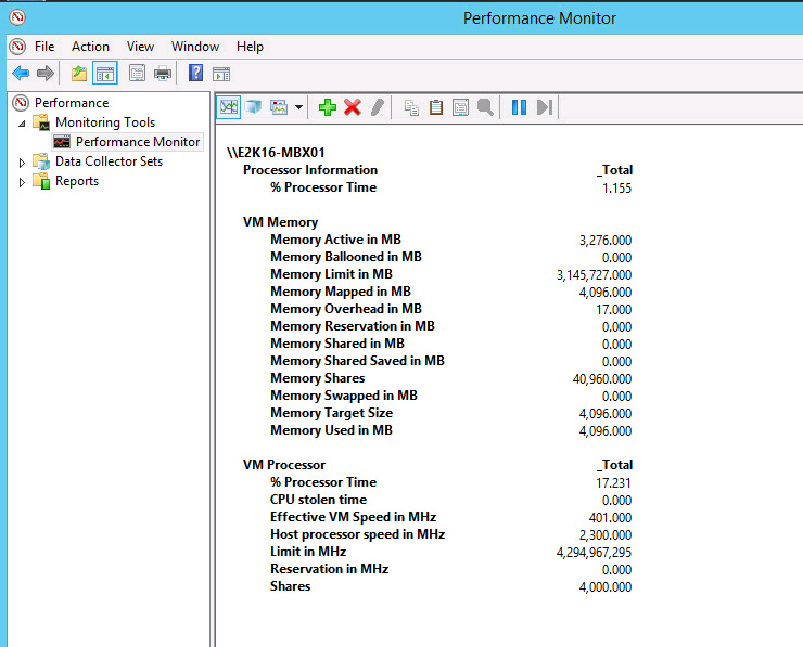
Many of the counters available can be used to help confirm allocations have been set properly when vCenter Server access is not available or for configuration monitoring. The following table lists counters that can be actively monitored.
Table 4. Virtual Machine Perfmon Counters of Interest
| Object | Counter | Description |
| VM Processor | % Processor Time | Processor usage across all vCPUs |
| VM Memory | Memory Ballooned Memory Swapped Memory Used | Amount of memory in MB reclaimed by balloon driver Amount of memory in MB forcibly swapped to ESXi host swap Physical memory in use by the VM |
vSphere and Exchange administrators can also use the counters listed in the following table to monitor performance at the ESXi host level. Those metrics can then be correlated with metrics from Exchange VMs. See the section on performance-monitoring utilities in vSphere Monitoring and Performance for a comprehensive list of performance counters and metrics in vSphere and for information on using vSphere-native tools to monitor an ESXi host and VM performance.
Table 5. VMware Performance Counters of Interest to Exchange Administrators
| Subsystem | esxtop Counters | vCenter Counter |
| CPU | %RDY %USED | Ready – milliseconds in a 20,000ms window Usage |
| Memory | %ACTV SWW/s SWR/s | Active Swapin Rate Swapout Rate |
| Storage | ACTV DAVG/cmd KAVG/cmd | Commands Device Latency Kernel Latency |
| Network | MbRX/s MbTX/s | packetsRx packetsTx |
The preceding table indicates a few key counters that should be added to the list of inspection points for Exchange administrators. Of the CPU counters, the total used time indicates system load. Ready time indicates overloaded CPU resources. A significant swap rate in the memory counters is a clear indication of a shortage of memory, and high device latencies in the storage section point to an overloaded or misconfigured array. Network traffic is not frequently the cause of most Exchange performance problems, except when large amounts of iSCSI storage traffic are using a single network line. Check total throughput on the NICs to see whether the network is saturated.
VMware Enhancements for Deployment and Operations
VMware vSphere provides core virtualization functionality. The extensive software portfolio offered by VMware is designed to help customers to achieve the ultimate goal of 100% virtualization and a software-defined data center (SDDC). This section reviews some of the VMware products that can be used in an Exchange Server 2019 environment virtualized on vSphere.
VMware NSX for vSphere
Although virtualization has allowed organizations to optimize their compute and storage investments, the network has mostly remained physical. VMware NSX® for vSphere solves datacenter challenges found in physical network environments by delivering software-defined networking and security. Using existing vSphere compute resources, network services can be delivered quickly to respond to business challenges. VMware NSX is the network virtualization platform for the SDDC. By bringing the operational model of a VM to a data center network, the economics of network and security operations can be transformed. NSX enables treatment of a physical network as a pool of transport capacity, with network and security services attached to VMs with a policy-driven approach.
VMware NSX Edge
Although the Client Access Servers (CAS) role has been coupled with the Mailbox Server role in Exchange Server 2019, client access to the Exchange infrastructure still requires efficient load-balancing to provide a highly available and well-performing experience for end users. To provide this functionality, hardware load-balancers are deployed in front of the Mailbox servers. If the load-balancer solution must be highly available, this can double the hardware investment required. In multisite deployments, this can mean up to four hardware load-balancers are required to provide a highly available load-balancing solution.
VMware NSX Edge™ provides load-balancing for VMs through a virtual appliance. NSX Edge can be deployed in a high-availability pair, providing better protection than hardware load-balancing solutions without the additional hardware or management overhead. The NSX Edge load-balancer enables application or service requests to be distributed across multiple back-end servers in a pool. NSX Edge Load Balancer includes the following functions:
- Virtual IP (VIP) Address – an IP address and service port number used by the user to access the service
- Server Pool – the pool of back-end servers that need to be load balanced. A VIP address is associated with the server pool.
- Service Monitor – defines the health-check parameters for a particular type of network traffic. A service monitor is associated with the server pool to monitor the pool members.
- Application Profile – defines the behaviour of a particular type of network traffic (e.g., the session persistence parameter and SSL parameters)
NSX Edge supports both Layer 7 (the recommended load-balancing option without session affinity requirements in Exchange Server 2019) and Layer 4 load-balancing of HTTP and HTTPS protocols. It supports multiple load-balancing methods, such as round-robin and least-connection. Layer 7 HTTP/HTTPS VIP addresses are processed after the NSX Edge firewall. NSX Edge uses the faster Layer 4 load-balancer engine. The Layer 4 VIP address is processed before NSX Edge firewall.
The NSX Edge services gateway supports the following deployment models for load-balancer functionality:
- One-arm load-balancer
- Inline load-balancer
One-Arm Load Balancer
The advantage of the one-arm load-balancer model is that it is simpler to deploy and is flexible. It allows deployment of load-balancer services (i.e., VMware NSX Edge appliances) directly on the logical segments where they are needed without requiring any modification on the centralized VMware NSX Edge that provides routing communication to the physical network. On the downside, this option requires provisioning of more VMware NSX Edge instances and mandates the deployment of source network address translation (NAT) that does not allow the servers in the data center to have visibility into the original client IP address.
The load-balancer can insert the original IP address of the client into the HTTP header before performing source NAT (i.e., a function named Insert X-Forwarded-For HTTP header). This provides the servers visibility into the client IP address, but it is limited to HTTP traffic.
Inline Load Balancer
The inline load-balancer model is also simple and allows the servers to have full visibility into the original client IP address. It is less flexible from a design perspective, as it usually forces using the load-balancer as a default gateway for the logical segments where the server farms are deployed, which implies that only centralized (and not distributed) routing must be adopted for those segments. The load-balancer is another logical service added to NSX Edge that is already providing routing services between the logical and the physical networks. Therefore, VMware recommends increasing the form factor of NSX Edge to X-Large before enabling load-balancing services.
Figure 24 - Load-Balancing Exchange Server 2019 with NSX Edge
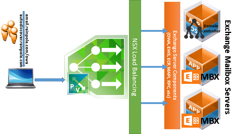
VMware NSX Distributed Firewall
Exchange 2019 can leverage VMware NSX for vSphere to provide application-layer isolation against unauthorized access. Isolation at this level typically requires hardware firewalls and multiple VLANs in a physical networking environment. With NSX Distributed Firewall, this capability is delivered in software through a kernel module.
The distributed firewall provides security-filtering and service-chaining functions on every host prepared for VMware NSX. The throughput scales as hypervisors are added.
The distributed firewall kernel module is embedded in the VMkernel. It is deployed as a VMware infrastructure bundle (VIB) during the host-preparation process.
The firewall rules are configured by the administrator using the vSphere Web Client or REST APIs. The NSX Manager stores the rules in its database and pushes the policies to the ESXi hosts through the message bus agent.
Different types of firewall rules can be created with VMware NSX.
Application-aware policies can use dynamic tagging and user identity. Infrastructure-aware policies can use vCenter inventory objects as the basis for rules. Network-based policies are the most common (and traditional) types of policies that use Layer 2 and Layer 3 data for the rules.
After upgrading the firewall to NSX, move the grouping objects used by firewall rules to global scope. To do this, use NSX APIs to create new grouping objects with the same members and then update the relevant firewall rules with the new IDs.
Figure 25. NSX Distributed Firewall Capability
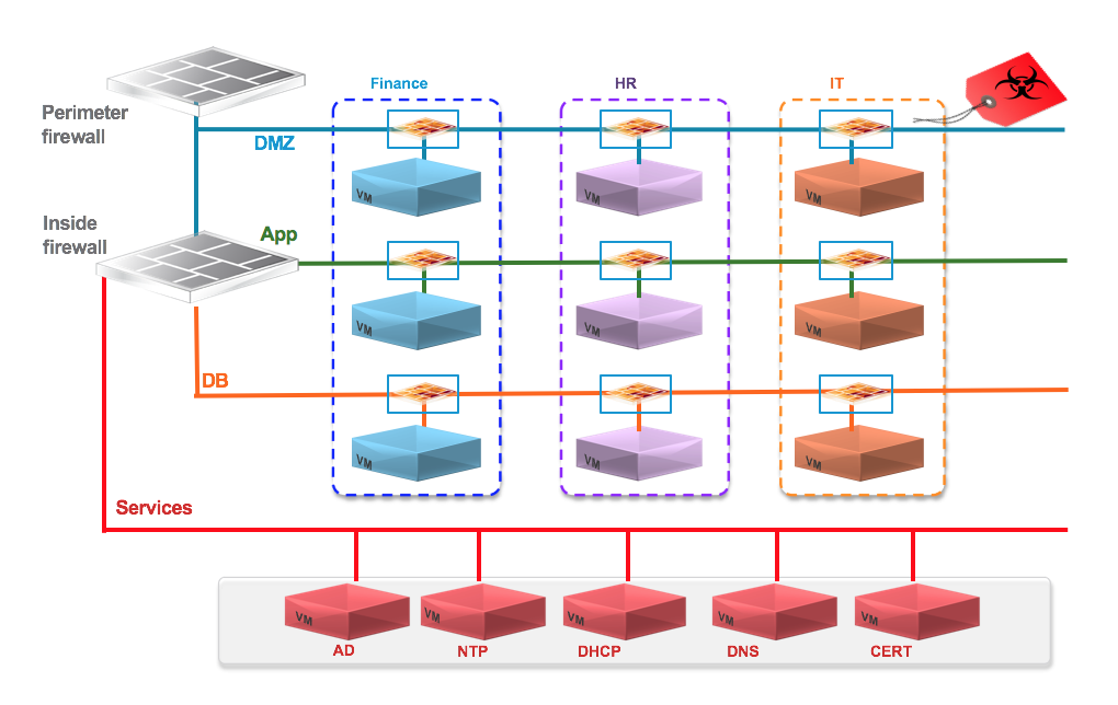
VMware vRealize Operations Manager
VMware vRealize® Operations Manager™ can provide a holistic approach to managing performance and capacity. By using patented analytics, service levels can be proactively monitored and maintained. When performance or capacity problems arise in an Exchange environment, vRealize Operations Manager is analyzes metrics from the application all the way through to the infrastructure, providing insight into problematic components, whether they are compute (physical or virtual), storage, networking, OS, or application-related. By establishing trends over time, vRealize Operations Manager can minimize false alerts and proactively identify potential root causes of performance problems before end users are impacted.
In an Exchange environment, constant monitoring is required to maintain acceptable service levels, not only for end users, but also for Exchange components. vRealize Operations Manager includes patented capacity analytics that can eliminate the need for spreadsheets, scripts, or rules of thumb. Administrators can quickly run through what if capacity scenarios to understand growth trends and identify upcoming compute power shortages or over-provisioned resources. As an application comprised of multiple components, Exchange performance and functionality can be affected by changes made at many levels. vRealize Operations Manager monitors configurations across VMs and detects unwanted changes to help maintain continuous compliance with operational best practices. Monitoring Exchange-specific performance metrics requires the deployment of Exchange-specific vRealize Operations agent on the Exchanged Server.
Figure 26. vRealize Operations
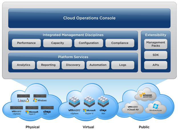
Site Recovery Manager
Site Recovery Manager takes advantage of VM-encapsulation to make testing, validating and initiating disaster recovery (DR) failover a straightforward, integrated vCenter process. Site Recovery Manager runs alongside vCenter Server to provide planning, testing, and automated recovery in the case of a disaster. By using VMware vSphere Replication or storage-based replication technology, Site Recovery Manager eliminates the manual steps required during a failover scenario to provide consistent and predictable results.
The following is a high-level overview of steps that can be performed with Site Recovery Manager during a test or actual failover.
- Shut down production VMs, if the production site is still reachable (actual failover)
- Promote recovery storage to primary (actual failover)
- Take and mount a snapshot of recovery storage in read/write mode (test failover)
- Rescan recovery site ESXi hosts to make storage visible
- Register recovery VMs, using placeholder (VMX) files representing protect VMs at DR site
- Power on registered VMs at the recovery site, in the exact order specified in the recovery plan
- Using information contained in recovery plan, reconfigure VM IP addresses, if required
- If configured, recovery step pauses for external administrator’s tasks
- Continue with recovery steps upon completion of administrator’s actions
- Verify that VMware Tools starts successfully on recovered VMs
- Execute any in-guest (or SRM server-hosted) scripts and commands specified in the recovery plan
- Notify administrators about completion
- Power off recovered VMs (test failover)
- Unregister VMs (test failover)
- Remove storage snapshot from the recovery side (test failover)
- Provide option to configure protection for recovered VMs, as soon as failed site becomes operational, or to another surviving site
Exchange Server’s native high-availability feature (DAGs) can provide high availability by implementing database-level intra- and inter-site database replication for some (or all) Exchange Server databases. Although DAG is an excellent choice for data center high availability, the application-centric nature of a DAG might not be in line with a company’s DR plans. In addition, configuring DAG for the purposes of timely and optimal recovery of Exchange services in the event of a catastrophic data center failure is complex, costly, and less reliable than leveraging the features and capabilities of the VMware Site Recovery Manager.
Site Recovery Manager is not a replacement for application-aware clustering solutions (such as DAG) that may be deployed within the guest operating system. Site Recovery Manager provides integration of the replication solution, vSphere, and optionally customer-developed scripts to provide a simple, repeatable, and reportable process for DR of the entire virtual environment, regardless of the application. Site Recovery Manager complements and enhances Exchange DAG capabilities by streamlining, automating and optimizing recovery operations in the event of a site-level disaster.
Figure 27. VMware Site Recovery Manager – Logical Components
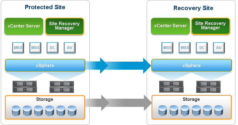
The Exchange 2019 Preferred Architecture prescribes a minimum of four DAG copies and three geographically-dispersed data centers to achieve a semblance of site-resilience and DR with DAG. Even with these requirements, the following impediments still make Site Recovery Manager a superior DR solution over DAG:
- No testing capability. Numerous changes happen over the life of a given IT infrastructure. Some of these changes invalidate previous configurations, scripts and processes, requiring iterative updates and testing. A DR plan requires reliability and assurance because an actual disaster event is a poor time to discover that a previously-configured recovery plan has been invalidated by evolving infrastructure changes. Site Recovery Manager enables continuous, periodic testing and reconfiguration of recovery plans without inducing interruption or service outage in the Exchange Server infrastructure. Simulating recovery from a site disaster event with Exchange DAG requires service-interruption for the duration of the simulation exercise. Post-simulation, returning the Exchange infrastructure to its prior state – a one-click operation with Site Recovery Manager – is also a complex undertaking, requiring multiple steps and a lengthy database reseeding operation.
- Cost efficiency. Site Recovery Manager is more cost-efficient, both in terms of administrative efforts and financial costs. Each of the four Exchange Servers is required to satisfy the preferred architecture design requirements of its own server hardware, OS, Exchange, antivirus and other application licenses, in addition to having the storage required to support the configuration. Even when configured with DAG as prescribed, the associated administrative, management and maintenance efforts required to support the design can become quickly overwhelming and prohibitive. With Site Recovery Manager, it’s possible to achieve a better DR solution with just a two-member DAG configuration, providing a better and less costly alternative to the preferred architecture design.
- Unified DR Solution. Exchange DAG is a high-availability solution for Exchange Servers and only Exchange Servers. An Exchange Server instance has multiple dependencies (e.g., active directory, backup and other messaging hygiene and security components), which are required to be available before Exchange Server services can be successfully recovered in the event of a site disaster. Recovering Exchange Servers alone in this configuration does not add much value unless the dependencies themselves are recovered as well. Site Recovery Manager is application-agnostic and suitable for protecting and recovering any server, including the dependencies that DAG cannot protect. The unification of a DR solution improves efficiency and reduces costs. In this case, administrators do not have to manage multiple DR solutions, removing confusion, complexity, and stress in an otherwise challenging DR event.
As stated by Microsoft:
“The specific prescriptive nature of the PA means of course that not every customer will be able to deploy it (for example, customers without multiple data centers). And some of our customers have different business requirements or other needs which necessitate a different architecture. If you fall into those categories, and you want to deploy Exchange on-premises, there are still advantages to adhering as closely as possible to the PA, and deviate only where your requirements widely differ”.
DR for a production, enterprise-level Exchange Server infrastructure is a critical design consideration that requires deviation from Microsoft’s prescriptive guidance.
The following is a high-level overview of Site Recovery Manager as a DR solution for an Exchange Server infrastructure. See the Microsoft Exchange 2013 on VMware Availability and Recovery Options Guide for a detailed discussion of this topic.
Figure 28. Challenges with Exchange Server DAG as a DR Solution
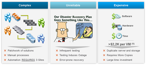
Using Site Recovery Manager to protect Exchange Server components (including DAG) and infrastructure is a fully supported configuration. Because Site Recovery Manager is application-agnostic, it does not interfere with, modify or otherwise affect Exchange Servers. Site Recovery Manager is not involved in the replication of VM files and data from a protected site to a recovery site. This function is performed by the applicable storage-replication components of the customer’s choosing. Site Recovery Manager provides the necessary storage API (i.e., storage replication adapter) required to interact with the underlying storage infrastructure. Site Recovery Manager does not need to install any agent or components on the VM.
Site Recovery Manager adds automation and orchestration capabilities to a virtual infrastructure, affording customers the ability to configure a comprehensive recovery plan that includes every facet of the recovery steps and actions required to restore services to an Exchange infrastructure in a DR scenario. Site Recovery Manager includes the capability to pause a recovery operation to allow for manual administrative intervention where required (for example, reconfigure DNS records or load-balancer configuration in a non-stretched network) as well as script callouts.
Figure 29. Faster Exchange Service Recovery with Site Recovery Manager Automated DR Workflows
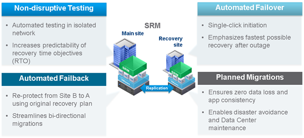
Site Recovery Manager supports all features of a vSphere infrastructure, including, DRS, vSphere HA, fault-tolerance, and virtual SAN (vSAN). vMotion support includes storage and cross-data center vSphere vMotion operations. While Site Recovery Manager supports configuring an isolated test network for testing DR plan, it does not require such configuration – a test failover operation auto-generates the fenced network that is required to isolate the recovered Exchange infrastructure from the production environment.
Site Recovery Manager provides multiple topologies and recovery options for protecting an organization’s Exchange Server infrastructure:
- Active-Passive. Site Recovery Manager supports the traditional active-passive DR scenario, where a production site running applications is recovered at a second site that is idle until failover is required. Although the most common configuration, this scenario also means costs are significant for a DR site that is idle most of the time.
- Active-Active. To make better use of the recovery site, Site Recovery Manager also enables leveraging the recovery site for other workloads when not in use for DR. Site Recovery Manager can be configured to automatically shut down or suspend VMs at the recovery site as part of the failover process so that it’s possible to more easily free up compute capacity for the workloads being recovered.
- Bi-directional. Site Recovery Manager can also provide bi-directional failover protection so that active production workloads can be run at both sites and failover to the other site in either direction. The spare capacity at the other site will be used to run the VMs that are failed over.
- Shared Recovery Sites. Although less common, some customers may need to be able to failover within a given site or campus, for example, when a storage array failure occurs or when building maintenance forces movement of workloads to a different campus building.
- Active-Active Datacentres. This is a new topology supported with metro-distance stretched storage solutions. Production apps run at both sites, and the stretched storage provides synchronous reads-and-writes on storage when sites are within a metro distance (less than 100 km). Site Recovery Manager is used to orchestrate recovery, or even live migration, of VMs between sites.
Figure 30. Failover Scenarios with Site Recovery Manager