
Protecting and Recovering Mission-Critical Applications in a VMware Hybrid Cloud with Site Recovery Manager
Overview
This Guide provides a comprehensive documentation of the considerations and configuration steps required for using VMware Site Recovery Manager™ (SRM) to protect and recover a reference multi-tiered set of Business-Critical Applications from a source datacenter (on-premises or cloud-based) to a target VMware hybrid cloud-based datacenter, with the least cost (time, financial, and administrative intervention) possible.
This guide is intended to be used by technical architects, administrators or operators as the basis for building similar solutions for their own enterprise infrastructure. Because it assumes that the reader is familiar with the general concepts of business continuity and recovery, this guide does not attempt to define or explain such concepts in any detail. This guide also does not seek to discuss or explain the setup, configuration, operation or administration of Site Recovery Manager, virtualization, VMware Hybrid Cloud or the applications and services hosted on or provided by the protected workloads.
The referenced mission-critical application stack used in this guide (described in the next paragraph) has not been chosen based on any specific technical or technological imposition or requirements of Site Recovery Manager, VMware vSphere® or VMware Hybrid Cloud. VMware's Site Recovery Manager protects a Virtual machine (VM) as an entity, without considerations for the Application hosted in the VM. It is application-agnostic. We have chosen the following set of applications as the use case for this guide solely based on the need to be comprehensive in demonstrating the capabilities of automation and orchestration as well as the simplification of infrastructure recovery tasks possible with Site Recovery Manager.
Terminologies and Applications used in this Guide
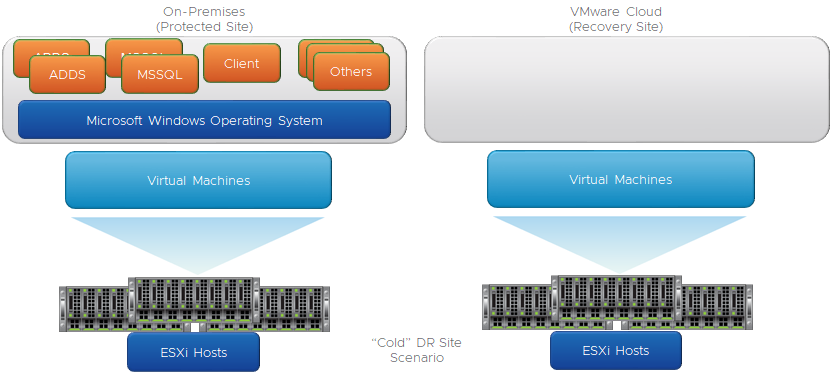
"Cold" Recovery Site Topology
Although distributing Servers and Services over multiple Datacenters is a common BCDR strategy, the associated costs of maintaining a dedicated DR site (staffing, cooling, heat, duplicate hardware) have made Cloud-based options more attractive than physical datacenter option for this purpose. An additional benefit of using the cloud-based options is that Enterprises can further reduce the associated costs by minimizing actual utilization of the cloud-located resources until it is necessary to do so - when an actual disaster event has happened, or during a simulation/testing/validation exercise. This type of "use only when needed" utilization is commonly described as having a "Cold Site" for BCDR purposes. In this configuration, no "live" (or "hot) device, server or service is hosted in the target DR site, saving Enterprises lots of money and resources in their BCDR plans. We will demonstrate how SRM achieves this cost-saving objective while at the same time providing the simplified, flexible, automated, and repeatable BCDR solution for enterprises.
Windows Active Directory Domain Controllers
Since Domain Controllers are ubiquitous in most enterprise network infrastructures because a large number of applications depend on the services they provide, most BCDR plans tend to include considerations and provisions for them. In the "Cold DR Site" scenario described in this guide, recovering modern versions of Windows Domain Controllers (anything newer than Windows Server 2008 R2) in the event of a Disaster is a little bit tricky and complicated, chiefly due to the security features Microsoft introduced into virtualized Domain Controllers beginning from Windows Server 2012. This Guide will cover this consideration and show how Site Recovery Manager helps minimize these challenges.
Microsoft SQL Server
Because of its integration with so many front-end applications, services, and solutions, Microsoft SQL Server is arguably one of the most prevalent Business Critical Applications one can find in any Microsoft-based corporate IT infrastructure. This close integration creates both upstream and downstream dependencies which can result in significant cascading negative impacts when Microsoft SQL Server instances experience unexpected or prolonged outages in production. Microsoft SQL Server has native, built-in resilience to maximize its availability, enabling Enterprises to minimize the possibility of service disruption in the event of an outage. Combining Windows Failover Clustering Service (WSFC) with the Microsoft SQL Server Always On feature is a high availability option that helps ensure that, in the event of a failure of a member of the node, the services (databases especially) become available faster than otherwise possible in the absence of these features. Even then, this resilience is more useful and intended for high availability (which protects against component or service failures) rather than for disaster recovery events. We shall now attempt to make a high-level distinction between an "HA" event and a "DR" event, for clarity.
Windows Client Machine
The third tier in our 3-tier workloads scenario is more for illustration than for technical purposes. We could have chosen, say, a Web Server providing front-end services and dependent on the SQL Server services. We have chosen an ordinary Windows client machine, from which we would test connectivity and access to the servers and services we will recover in our failure scenarios. Come to think of it, what is the value of a disaster recovery exercise if it does not include facilitating clients’ and administrative access to the recovered resources?
“High Availability” vs “Disaster Recovery”
Application High Availability is more focused on an application’s ability to continue to operate and provide services even when the application's component(s) or the application itself has failed. This application's ability to survive (and recover from) failures is largely dependent on the resilience built into the application (either natively or through the use of third-party solutions or add-ons). In the scenario documented in this guide, the application-level resilience is provided through the combination of Windows Server Failover Clustering (WSFC) and the Microsoft SQL Server Always On features. These features enable the Services provided by Microsoft SQL Server to continue to be available (after a brief interruption) even after the original Server providing that Service has become unavailable for any reason. When the original Server fails, WSFC brings up its resources on a surviving node, usually without any administrative intervention. This, in a nutshell, is Microsoft SQL Server's "High Availability".
A Disaster Recovery event, in contrast with what we just described above, is a catastrophic failure impacting more than just a component or a Server. Without regard to its severity or duration, a disaster event can be described as a superset of multiple HA events which cannot be easily overcome by the resilience of a specific application, component or service. Because it is hardly ever transient in nature, the effects of a Disaster event are more impactful, disruptive and destructive on an Enterprise. Also, because, in a disaster event, multiple layers of the infrastructure are negatively impacted, recovering from such event is considerably more difficult, expensive, and slower compared to recovering from an HA event. Consequently, preparing and planning for recovering from a disaster event is materially and financially more expensive.
Assumptions
Because this guide is strictly focused on demonstrating how to use SRM to protect virtualized Business Critical Applications to any VMware vSphere-based Hybrid Cloud, a detailed description of the following topics is out of focus:
- Installation, setup, configuration and/or administration of VMware vSphere infrastructure
- Installation, setup, configuration and/or administration of specific VMware vSphere-based Cloud infrastructure
- Installation, setup, configuration and/or administration of VMware Site Recovery Manager
- Installation, setup, configuration and/or administration of Microsoft Active Directory Domain Services or Domain Controllers
- Installation, setup, configuration and/or administration of Microsoft SQL Server, Windows Failover Cluster or Always On
We assume that the infrastructure to perform these tasks has been configured as recommended in the applicable references.
Requirements
The following are expected to have been completed before undertaking the configuration and other tasks demonstrated in this guide:
- Network connectivity between (or among) the source infrastructure. We will henceforth refer to this as the "protected site".
- Network connectivity between (or among) the target infrastructure, which could be any of the publicly available brand of the VMware Cloud infrastructure options (VMware Cloud on AWS, Azure VMware Solution, Google Cloud VMware Engine). We will henceforth refer to this as the "Recovery Site".
- The "Network Connectivity" type required for VMware SRM is dictated by the VMware Cloud brand and version - consult the Cloud Provider's reference materials for more information.
- Successful installation of VMware SRM on both the protected and recovery sites.
- Successful installation of VMware vSphere Replication appliances in the same vCenter Server in which the SRM instance is registered on each of the sites.
- Environment configuration information (VM IP addresses, DNS Server IP addresses, Network segment, datastore) is required to complete the protection and recovery plans.
- All the VMs which are to be protected and recovered by VMware Site Recovery Manager have an up-to-date version of the VMware Tools installed (Note: This is a standard recommendation, but it is especially relevant if the VMs will be reconfigured or customized as part of the Recovery process)
Setting up BCDR Environment and Workflow in VMware vSphere Site Recovery Manager
Now, let's get technical.
The process of configuring VMware SRM to protect and recover workloads begins with the pairing of the Protected and Recovery Sites. SRM administrative interface is integrated into the VMware vSphere Client interface. The exercises presented in this guide will be conducted entirely through these Web interfaces, with the exception of a few review tasks conducted inside the recovered workloads (Windows Operating System, Active Directory Domain Services (ADDS) and Microsoft SQL Server) to confirm functionalities after recovery.
Here is the SRM interface on the Protected Site.

Here is the SRM interface on the Recovery Site.

We will be completing most of the tasks in this exercise from the Protected Site, so let's get started
- Click on "OPEN Site Recovery"
We are now going to connect the vCenter and SRM instances on each site to one another. This is called "Pairing the Sites".
- Click on “New Site Pair”.

We are prompted for the vCenter Server Credentials.
Because we are doing this from the Recovery Site's vCenter instance (our VMware-based Cloud BCDR environment), the credentials we provide here will be for the Protected Site's vCenter instance. 
Note: If you are using default self-signed certificates in your environment, you will need to click "Connect" to ignore the vCenter's self-signed certificate security warning and proceed.

We are using VMware vSAN for the Storage subsystem in our environments. vSAN is the default Storage option for all VMware vSphere-based Cloud infrastructure. In this configuration, we see that the SRM and the VMware vSphere replication appliance are both registered on our vCenter Server
- Click "Next" to continue
Note: If you are using default self-signed certificates in your environment, you will need to click "Connect" to ignore the vCenter's self-signed certificate security warnings and proceed.
Click "Finish" to complete the Site Pairing process.

Now we are done with the Site Pairing exercise.

- Click "View Details"

- Provide the admin credentials for the Protected Site's vCenter Server, then click "Login" to complete the initial pairing.

Factors Influencing our Design and Configuration Choices
Before we begin putting all the pieces in place, let's describe our objectives in more detail.
VMware SRM allows you to configure an orchestrated workflow of all the actions and steps required to recover a VM including the guest operating system, applications, processes, etc. SRM does this by using the features and capabilities of the VMware vSphere infrastructure and the storage subsystem to create a point-in-time copy of the VM at the Source (Protected Site) to the Target (Recovery Site). SRM can utilize either array-based replication or vSphere Replication to replicate VM data from a source site to a target site. For this paper, only vSphere Replication was used.
Because vSphere Replication is host-based replication, it is independent of the underlying storage and it works with a variety of storage types including vSAN, traditional SAN, NAS, and direct-attached storage (DAS). Unlike many array replication solutions, vSphere Replication enables virtual machine replication between heterogeneous storage types. For example, vSAN to DAS, SAN to NAS, and SAN to vSAN. vSphere Replication can, of course, replicate virtual machines between the same types of storage, such as vSAN to vSAN.
When a (real or simulated) failure occurs at the Protected Site, administrators are enabled to initiate the pre-configured recovery steps and actions (recovery plan).
These steps include (among others) the order in which SRM recovers the protected VMs; the network to which the recovered VMs are connected to; whether to customize or change the IP addresses for the recovered VM (or let them obtain such addresses from an available/accessible DHCP Server; in-Guest configuration scripts to run on the recovered VMs, etc.
When an administrator initiates this recovery plan, SRM uses the copy of the VMs data created by vSphere Replication to prepare the VMs for recovery. The VMs are added to inventory, connected to the appropriate resources (networks, folders, resource pools, and storage policies, powered on in the order specified and customized as required. If the workflow includes running scripts inside the VMs as part of the process, the guest operating system is instructed to call and run the scripts (of course, the scripts must exist on the VMs and be accessible during the recovery process).
Here is a high-level description of the protection and recovery workflow we will configure for our exercise.
- The SQL Server instances in our use case run on VMs running the Windows Operating System and are joined to the Active Directory Domain Services (ADDS) infrastructure. For this reason, we need the Domain Controllers to be available and functional before the SQL Server VMs are brought up.
- Our SQL Server instances are clustered in a 2-node always-on availability group configuration. Clustering SQL Servers requires the use of a Windows Server Failover Cluster. We are using a file share witness (a folder located on one of the domain controllers) as the quorum option for this configuration.
- We specifically use Availability Groups in this Guide and demonstration because (as of the time of this writing):
- The default storage option for VMware Clouds is vSAN
- The default replication option for vSAN is vSphere Replication
- vSphere Replication does not currently have the capabilities to replicate disks used for shared-disk Windows clustering
- Although the scripts and all other required steps are similar, the factors mentioned above preclude the use of the steps documented in this guide for protecting and recovering Microsoft SQL Servers configured in shared-disk mode – Always On Failover Clustering Instance (FCI).
- In steady state operation, applications, scripts, and processes access the SQL Server instance and the database through a common name (called "Listener"). The Listener is (simply) a host name that resolves to a specific IP address. This resolution is handled by the DNS Service provided by our Domain Controllers. This IP Listener is a resource that must be available for the services provided by our SQL Servers to be accessible.
- Usually, the IP address segments in our Protected Site are different from the ones used in our Recovery Site.
- It is possible to extend our network segments from the Protected Site to the Recovery Site. Because the mechanism for achieving this configuration differs among the various brands of VMware Cloud, it is impractical for us to include this consideration in this guide. For simplicity, our exercise will include the workflow to change the IP addresses of the recovered VMs to match what is available at the Recovery Site.
- This choice of IP address change means that, we will not only need to change the VM's IP (a trivial task in SRM), but we will have to also change the IP address of the Listener described in the previous paragraph.
- Because SRM orchestrates and automates the protection and recovery of VMs without any insight into the Applications hosted therein, it is impossible for SRM itself to make Application-level configuration changes as part of its automation process. For this purpose, we will be using the script-triggering feature of SRM to instruct the guest operating system to run a script, which will change the IP address of the Listener and update the record in DNS after the recovery.
- Around 2012, with compute resources getting larger and virtualization maturing and becoming well-accepted in the enterprise, dedicating a Physical Server to running a domain controller became impractical and inefficient from a cost and ROI perspective. Security and stability concerns with virtualized Domain Controllers prompted Microsoft to introduce some measures to make virtualized Domain Controllers safer and more stable. One of the concerns addressed by these measures is the ease with which an insider or attacker with elevated privileges in the virtual infrastructure can make a copy of a virtualized domain controller (either by cloning it or just making a copy of the VMDK). These measures are implemented mainly through what is known as VM-generation ID.
- What does VM-Generation ID do? It makes virtualizing domain controllers a much safer proposition.
- Because, at a high level, a domain controller has a full copy of the Domain's users, passwords and other secrets, the effect of such an attack cannot be easily minimized or mitigated. Among other capabilities, VM-Generation ID helps prevent the type of attack described earlier by:
- Storing and tracking a unique counter for every copy of a virtualized domain controller - the Hypervisor assigns a counter to the VM (in vSphere, this is the "VM Gen-IDx" value you see in a Windows VM's vmx file).
- When the Domain Controller boots up, it reads this counter from its configuration file and then stores it internally.
- This counter persists over the lifetime of the VM - unless a specific type of operation (listed here) is performed on that VM. These actions alter the state and identity of the virtual machine, so whenever any of them is performed, the hypervisor changes the counter.
- The next time the Domain Controller is powered-on, Windows will read its generation ID, compare it to what was previously stored and discover that there is a mismatch.
- When this happens, Windows immediately takes a number of steps in response to the disparity and triggers the safety measures provided by the VM-Generation ID feature. Please refer to the following link for a more detailed discussion of "Virtualization-based Safeguards”.
- SRM recovery workflow includes bringing up A REPLICATED COPY of a Protected VM at the Recovery Site when (in a real Disaster event) the real Domain Controller is unavailable) or in a simulated DR exercise (when the VM is recovered to a fenced-off "Test" network). Recovering a domain controller requires us to instantiate a replicated copy of a real Domain Controller. Such a "Copy" operation automatically changes the VM-generation ID of the domain controller, which then automatically triggers the domain controller safety responses from Windows.
- One of the responses is an instruction to the domain controller to (among other things) reset its InvocationID and discard its RID Pool. For all practical purposes, the domain controller is no longer a domain controller at this point, due to the change in its VM-generation ID. Windows then updates the VM-generation ID it had stored previously to match the new one provided by the hypervisor. The VM then obtains a new set of RID Pool from the RID Master, and life is good. Well, we have abbreviated the complete narrative for our purposes, but what is of relevance to us for this Guide is that, in spite of the fact that recovering a domain controller with SRM triggers Windows to invoke the Virtualized Domain Controller Safety feature, doing so is a supported, repeatable, more efficient, reliable, and faster option than anything else available as of the time of this writing.
Putting it all Together
Now that we know our desired outcome and the considerations governing our ability to achieve it, we are ready to proceed.
Here is an approximate representation of the logical topology of our SRM Infrastructure

This is what our paired SRM initial configuration looks like.

vSphere Replication Server will be responsible for replicating our protected VMs from the Protected Site to the Target Site (and vice versa). No special configuration is required for this part at this point.
We will ignore the "Array Based Replication" part because it does not apply to vSAN, which is the default storage option for VMware Cloud.

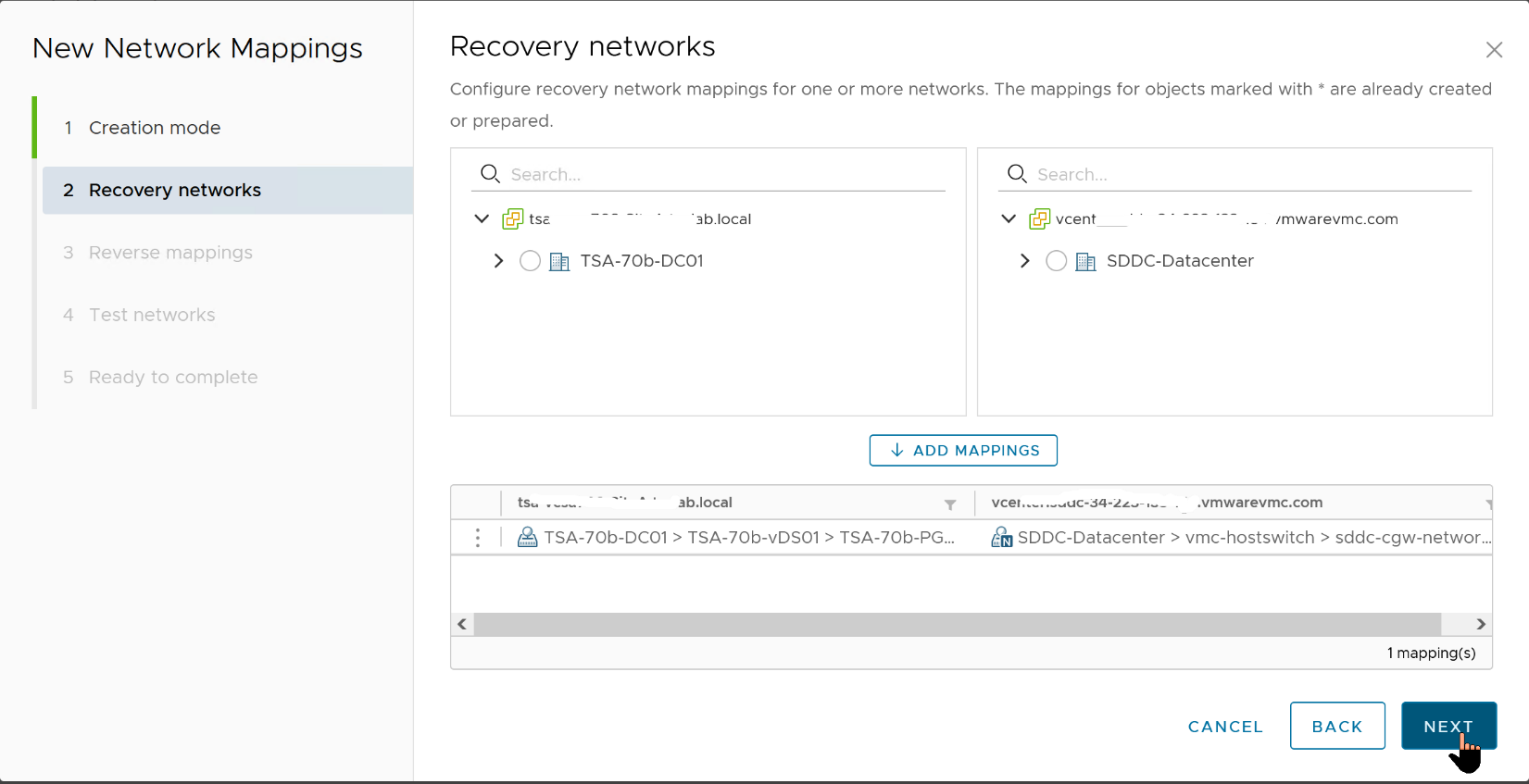
Network pairing allows us to map the network segments on one side to a corresponding segment on the other.
- Click "New" to begin creating our mapping

Select "Prepare mappings manually" because we would like to be able to select the specific mappings we desire.
Click "Next".

We will choose to map at the virtual Distributed Switch (vDS) level, instead of selecting an individual Port group to map. This is just for simplicity.
- Select the radio button near the vDS on each site and click "Add Mappings".
- Click "Next" to proceed.
- Click the option to automatically create a reverse mapping, just so we do not have to do it manually.
- Click "Next".

One of the most compelling features in SRM, and, consequently, why it is much preferred over competing for BDCR orchestration Solutions (or manual option) is being able to conduct simulated (Test) Disaster Recovery exercises without impacting the production environment. Administrators can demonstrate and prove their infrastructure Disaster Recovery readiness by conducting a recovery of the Protected workloads into the Recovery Site while the Protected workloads continue to provide uninterrupted services at the Protected Site. SRM does this by bringing up a copy of the Protected workload in an isolated network segment at the Recovery Site. SRM creates this isolated network by default, but Administrators can choose to specify their own Recovery Test (aka "Bubble") network. The default isolated network is inaccessible to anything outside of the bubble, but what if an Administrator wants to demonstrate functionalities and accessibility of recovered workloads to their auditors? They can do this by recovering the workloads into a specific network of their choices (assuming they have such controlled network in place).
- For this guide, we will accept the default "Isolated network (auto created)" option.
- Click "Next" to continue.

Click "Finish" to proceed.

If we decide later that we would like to use a dedicated, fenced-off network segment for our Test Recovery Plans, we can always go back to "Network Mappings", select the configuration we want to edit (or create a new one), click the "..." on the right-hand side, and click on "Edit Test Network Mapping" from the menu.

- Click "Select a specific network" and pick the dedicated and isolated recovery network you have prepared for this purpose.
- Click "Next" when done.

“Folder Mappings” helps us organize our protected and recovered VMs in a logical and intuitive fashion, so let us create one:
- Click "New" to begin.

- Click "Next".

- Select the VM Folders to match up, then click "Next".

- Select the checkboxes to accept the option to automatically create a matching Folder Map in the opposite direction.
- Click "Next".

- Click "Finish".

- For "Resource Mappings", we will (again) just map our resources at the highest level possible (Cluster level, in this case).
- Click "New" to begin.

- Select the Cluster containing your protected workloads and map it to the cluster you would like for them to be placed in at the Recovery Site.
- Click "Add Mappings", then click "Next"

- Accept the option to auto-configure a reverse mapping, then click "Next".

- Click "Finish" to complete the process.

When SRM uses vSphere Replication to replicate a Protected VM to the Recovery Site, it also creates a representation of the VM in the vCenter at the Recovery Site. This representation is somewhat similar to the vmx file that describes the running VM at the Protected Site. The major difference is that this representation is just a placeholder (aka "Stub"), which cannot be powered on. This placeholder file is stored in a designated datastore, which is not the same datastore that has the full replicated copy of the protected VM. The "Placeholder" Datastore needs to exist on both sides, to enable SRM to protect workloads in either direction.
Here is our Placeholder Datastore at the Recovery Site:

Here is our Placeholder Datastore at the Protected Site:

For SRM to protect and recover a VM, a copy of that VM must make its way from the Protected Site to the Recovery Site. Let us set up the replication part of the exercise now.
In this Guide, the Source (Protected) Site is our on-Premises VMware vSphere infrastructure, so let's switch to that and create our "Outgoing" Replication.
- Click "New".

The Target (Recovery) Site is our VMware Hybrid Cloud infrastructure, which the process auto-identifies (because they are already paired).
- Leave the option to auto-assign vSphere Replication Server at default and click "Next".

Here is where the previous "Mapping" exercises we completed in previous steps begin to pay dividends. Because we mapped only a specific VM Folder, we can focus our attention on only the specific workloads we would like to replicate as part of our Disaster Recovery operation.
- For our purpose, all the VMs in this folder are in-scope, so we will select all of them and click "Next".

- We select the target datastore.
- NOTE: The option to "Auto-include new disks in replication" is one of the amazing things about vSphere Replication. It anticipates situations where a Protected VM's configuration could change at a later date after we have set up our DR plans. With this option, vSphere Replication automatically incorporates the changes into the replication tasks
- Select this option, then click "Next".

RPO/RTO, Run Book, Protection Group and Recovery Plan Defined
"RPO" and "RTO" are probably two of the most over-used acronyms when discussing Disaster Recovery of Mission Critical Applications in the Enterprise. We have consciously avoided mentioning them until now because (as technical topics) they deserve whole book-length attention which we cannot accommodate in this guide. So, simply put:
- RTO (Recovery Time Objective) is the term used for measuring how long it would take an enterprise to recover from a disaster event and begin to operate at tolerable capacity. The "Objective" is to make this window as short as technologically and humanly possible.
- Because an RTO is influenced by several external, environmental, and infrastructural factors, we will not be demonstrating this consideration in this guide.
- RPO (Recovery Point Objective) is the term used for measuring the tolerable loss of services or data in a disaster event. It measures the up-to-dateness of the Enterprise's data after such an event. While every administrator, operator and business owner/stakeholder desires an RPO of 0, financial, human and technological constraints make such desire difficult to attain at this time.
vSphere Replication provides a 5-minute RPO at best. This means that, all things being equal, vSphere Replication attempts to synchronize and replicate every state change in the Protected VM as frequently as every 5 minutes. This means that, at any point in time, the copy of the VM at the Recovery Site is identical to the original Protected VM as of no more than 5 minutes ago. On the extreme end of the spectrum, vSphere Replication can also be configured to maintain a 24-hour RPO.

'%3E%3Cpath id='Rectangle_1' data-name='Rectangle 1' d='M0,0H800V300H0Z' transform='translate(2297 1132)' fill='%23E2F0D9'/%3E%3Cg id='Group_5' data-name='Group 5' transform='translate(-6 -3)'%3E%3Ctext transform='translate(2534 1280)' font-size='50' font-family='Roboto-Regular, Roboto'%3E%3Ctspan x='0' y='0'%3ECurated Assets%3C/tspan%3E%3C/text%3E%3Ctext transform='translate(2611 1333)' font-size='20' font-family='Roboto-Regular, Roboto'%3E%3Ctspan x='0' y='0'%3ETile View (with image and controls)%3C/tspan%3E%3C/text%3E%3C/g%3E%3C/g%3E%3C/svg%3E)
We will skip discussion of the other capabilities and features on this screen because they are well documented in the vSphere Replication Admin Guide and they are unimportant for this guide.
- Let's set our RPO to 5 minutes and click "Next".

- Review the choices, then click "Finish".

We are done with setting up the replication.

We spent some time discussing upstream and downstream dependencies earlier in this guide. Enterprise-scale Business Critical Applications generally do not exist or operate in a vacuum.
They depend on other services and workloads, and they are similarly dependent upon by others. When designing a BCDR plan, these dependencies influence configuration and workflow choices and options. SRM provides a mechanism for grouping protected workloads together in a way that helps us control their recovery in an orderly fashion to achieve our recovery objectives. A Protection Group in SRM is one such grouping.
A Protection Group contains VMs that we intend to recover together as a unit for any number of reasons. Many factors (the type of storage and the unit of replication are common examples) influence the decision-making processes involved in creating and using Protection Groups.
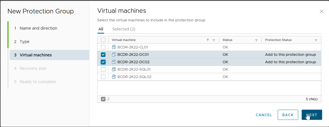
For our purpose, we will create Protection Groups based on the services and characteristics of the VMs we are protecting and recovering. We have three distinct categories (Domain Controllers, SQL Server and a Windows Client), so this is the primary influence on our configuration choice.
Click on the "Protection Groups" tab and select "New".

- Give the Group a descriptive name.
- Description is optional.
- The Direction is from our Protected Site to our Recovery Site.
- Click "Next".

Because we are using vSphere Replication here, we select “Individual VMs…” and click "Next"

- This is for the Domain Controllers, so we will select the applicable VMs and click "Next".
A Recovery Plan is where we define and configure the recovery steps, plans and actions guiding our entire BCDR Plan. You can imagine it as the "Run Book" to which an administrator would typically refer to and follow if they were to perform a Disaster Recovery operation manually.
The SRM Recovery Plan contains all the logic and flow of getting the copy of the Protected VM up and running in the Recovery Site when a disaster is declared, and the recovery is initiated. Recovery Plans contain at least one Protection Group which, as we have seen, is a grouping of the VMs we are protecting.
A Protection Group must be added to at least one Recovery Plan. We do not have a Recovery Plan yet, so we will create one here:
- Choose "Add to a new recovery plan"
- Give it an intuitive and descriptive name, then click "Next"

- Review the result, then click "Finish".

One of the most common tasks you would like to perform on a recovery plan is to configure the specific Test ("Bubble") network you would like to recover VMs into during a "Test Recovery" exercise:
- To do this, select the Recovery Plan, then click on "Edit".

From this menu, you can select the "Test Network" you prefer for this Recovery Plan.

We will repeat the process to create an additional recovery plan for each of the other types of workloads in our use case.

For each of these Protection Groups, we create a corresponding Recovery Plan. We do this because, based on our need to ensure that one group of protected workloads (the Domain Controllers) becomes completely available before the others are brought online, we want to be able to initiate the recovery of each workload type separately.
Here are our Recovery Plans

We have previously mentioned that Recovery Plans are essentially the Run Book for BCDR Projects in SRM. We shall now proceed to define the elements of our Run Book in each of the Recovery Plans.
We are going to configure the "BCDR-DC-RP01" Plan, which is the Recovery Plan covering our Run Book for recovering the Domain Controllers.
- We click on the name to select it.

- Select the "Virtual Machines" tab to display the VMs covered by the Plan.

Select the checkbox next to the VM we want to configure, then click "Configure Recovery".

SRM Recovery Plan gives us many configuration options and flexibility for controlling the desired outcomes for our Disaster Recovery Run Book. As you will see shortly, among other configuration options, here is where we can configure SRM to change the IP address (and other necessary IP configurations) to the recovered VM.
Virtualized Domain Controller Safety Feature
One of the challenges we want to overcome in recovering Domain Controllers is the order in which we want them to come up to account for the "Virtualized Domain Controller Safety" feature we discussed earlier. Since restoring a Domain Controller from a backup copy forces the Domain Controller to discard its RID Pool, you are likely wondering "where then does it get a new pool of RIDs if the RID Master is unavailable?"
This is a legitimate question in a Disaster event where we assume that everything in the Protected Site (including the RID Master itself) is unavailable. Luckily for us, the "DC Safety" feature accounts for this scenario by allowing the restored/recovered Domain Controller to regain services after multiple reboots (or by manually forcing the DC's NTDS to start "restart-service NTDS -force")), if it can communicate with another Domain Controller).
We will start by ensuring that we are recovering the DC holding the FSMO Roles first and then recover all other DCs only after this one has been fully recovered. The mechanism for doing this in SRM is the "VM Dependencies" option.
Here is how we do this for DC02, which depends on DC01 (the FSMO Roles holder):
- We select the VM (DC02) we want to make dependent and click "Configure Recovery"
- Expand "VM Dependencies" and select "View all". This will show us all the VMs in the Recovery Plan
- Select the VM we want this VM to depend (or wait) on, then click "OK"

Next, we will add a "Post Power On Step" task to DC01 which calls a Script within Windows to reboot the VM after it has been fully recovered. This is a very simple "Shutdown -r -t 0" command, nothing fancy. This reboot allows DC01 to be able to self-heal and start its relevant services, which allows it to be available to heal DC02 that depends on it.
Here is how we do that.
- We select DC01 and click "Configure Recovery".
- Expand "Post Power On Steps", then click "New".
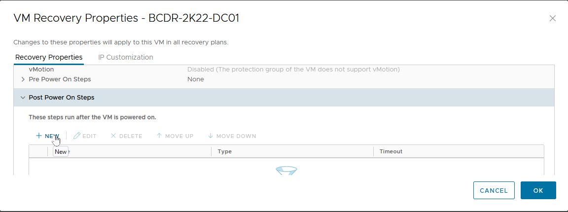
- Select "Command on Recovered VM".
- Give it a descriptive name.
- Type in the Command to run (in our case, we are calling a PowerShell Script named "Run-Post-Script.ps1", located in the "C:\Install-Files" folder.
- Click “Add”.

This brings us back to the "VM Recovery Properties" menu.

Here is the content of our "Run-Post-Script.ps1" script.

Changing Recovered VM’s IP Settings in SRM
Now, we are going to configure the TCP/IP Settings for our Protected VMs:
- Let's go back to the "VM Recovery Properties" menu, and click on the "IP Customization" tab.
- Select the drop-down button in "Select IP Customization Mode".
- Select "Manual IP Customization".

Click on "IP Settings - NIC 1", then on "Configure" next to "Protected Site".

- Click on "Use the following IPv4 address", then click "Retrieve".
- This auto-populates the fields with the current IP address of the VM.

- Let's repeat the process for the DNS information (we will skip IPV6 and WINS sections for this exercise).
- Click "OK" to complete the configuration.

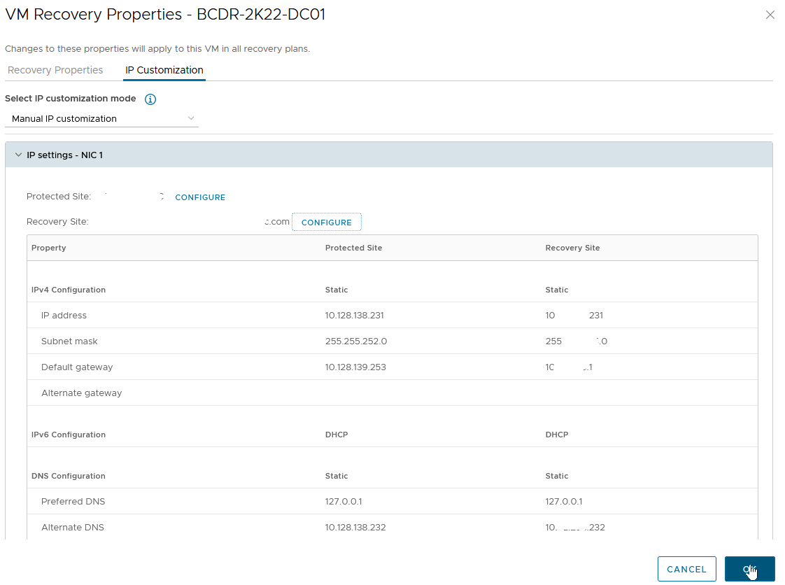
- This brings us back to the "VM Recovery Properties" -> "IP Customization" screen.
- We will click on "Configure" next to "Recovery Site" to specify the IP Address information we would like to apply to the VM upon recovery.
- You will notice that the "Retrieve" option is not available on this screen because the values do not currently exist on the VM.
- We go through the same steps we did for the "Protected Site" values, then click “OK” to complete the configuration.
We will complete this process for all the VMs in all recovery groups unless we:
- Want them to get their IP Address configuration information from a DHCP Server/IPAM available at the Recovery Site, or
- Want them to keep the same IP address because we have stretched the Protected Site's network segment(s) to the Recovery Site

In our use case, we have two SQL Servers in a Protection Group and created a Recovery Group for them. We have created a dependency between the two of them such that SQL02 would not be recovered and powered on before SQL01 has been fully recovered.

Considering that there are only two of them, and that the File Share Witness (FSW) is stored on a Domain Controller which we have already recovered before recovering the protected Microsoft SQL Server VMs, and any of the Microsoft SQL Server VMs that come up first will be able to form a majority node quorum by adding its vote to the FSW's vote to bring up the Cluster resources, why then are we creating a dependency?
We are doing it for the Listener and Cluster Virtual IP configurations. The parameters for these two Windows/SQL Server clustering configuration settings must be correct and available for the Cluster and its resources to become available after recovery.
As you have seen, the recovery process changes the IP address of the recovered VMs and connects them to a different network segment in the Recovery Site. Consequently, the Listener's and Cluster VIP's IP Addresses also need to change. This is something that SRM cannot do natively (because it is Applications-agnostic).
We will use the in-Guest Script initiation capability of SRM to make the changes (just like we did for the Operations Master domain controller). Because we only need to do this once for the Cluster, we have placed the Script inside only one of the SQL Server VMs, and that VM is SQL01. We, therefore, want the SQL01 VM to be recovered first and for the configuration changes to be completed before SQL02 is recovered.
Here is what that configuration looks like on SQL01.

Here is the SRM Guest-side Command which calls our in-Guest PowerShell Script (Change-Cluster-AG-VIP.ps1), located in the E:\Install-Files folder on the SQL01 VM.
NOTE: Follow your internal Corporate Security practices for storing and running in-Guest Scripts when deciding where to place these sample scripts.

Here is a screenshot of the Script (this Script itself will be included as an appendix to this guide).

SRM and Test Disaster Recovery
We now have all the configuration pieces, and we are ready to test our DR Plan. Of what use is a BCDR Plan if you cannot test it periodically? An actual DR event is not the best time to discover that your DR Plan is missing one or more steps or that the expectations were based on configuration assumptions that have changed so much that they no longer match current steady state realities.
- From the "Recovery Plans" tab, click on "Test".
- Notice that the "Plan Status" shows "Ready". This is an indication that the Recovery Plan is in a state where it can be successfully initiated.

- Confirm that "Replicate recent changes to recovery site" is checked, then click "Next".
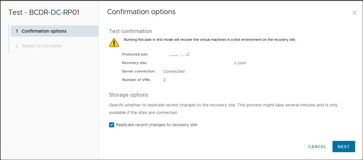
- Click "Finish" to begin the Test Recovery process.

The "Recovery Steps" shows detailed information about actions taken during the recovery process.
If we take a close look at what happened when we initiated our DC Recovery Plan, we will notice that DC02 was powered on only AFTER DC01 has fully recovered AND the in-Guest Script that we configured had been run. This is the "Dependency" we configured in the Recovery Plan.

We can see the recovered VMs powered on and run in the Recovery Site vCenter.

The same Domain Controller VMs are still running uninterrupted at the Protected Site.

Let's verify that both protected and recovered VMs are accessible by logging into them.

Safe Active Directory Domain Controllers Recovery with VMware Site Recovery Manager in Action
Let's take a look at what happened to our protected Active Directory infrastructure after a (simulated) Disaster Recovery event was completed using Site Recovery Manager.
- The first time the recovered Domain Controllers boot up, Windows automatically detects the change in their VM-Generation ID.

- Windows' DC Safety feature immediately kicks in and the recovered DC are taken through the remediation process. Among other effects we have discussed in previous sections, the Netlogon, DNS, and other services are unable to start during this remediation process.

- The FSMO Role holder (DC01) does not even consider itself a DC anymore (at least not an authoritative one).

- After rebooting the FSMO Role Holder (DC01) the second time (with our in-guest Script), things begin to look better.

- At this point, the DCs have discarded their RID Pool, obtained a new set, have a new Invocational and can begin to use a new batch of USNs.


- Windows has also accepted the new VM-Generation ID generated for the VM by our SRM Recovery exercise. The window will now store this for subsequent comparison next time the VM is rebooted

- DC02 has also been successfully remediated. Because it is not the FSMO Role holder, part of its healing process (for example, obtaining a new RID Pool) had to be supported by the availability of the Role holder.

Recovering Microsoft SQL Server (AG) with VMware Site Recovery Manager
Now that the Domain Controllers have been recovered at the Recovery Site, we are ready to recover our Microsoft SQL Server Availability Group cluster. Remember that our objective here is to ensure that we do not just recover the individual VMs, we also want to recover the services they provide. This means that, upon recovery, the cluster service and resources (databases, jobs, scripts) also have to be available, accessible and operational.
Let's start our Microsoft SQL Server Recovery Plan, following the same process as we did for the DC Recovery Plan above.
Take note of the startup sequence of the two VMs in our Recovery Plan. SRM does not begin to power on SQL02 until SQL01 has completed bootup and the in-Guest Script has been called - this is Dependency at work.

Recovery done

How is our Microsoft SQL Server Cluster doing? Let’s log into Windows and check.
- Windows Server Failover Clustering supporting SQL Server Availability Group is fully functional


- The Microsoft SQL Server Listener resource is also up and available.

Since this is a TEST Recovery exercise, let’s confirm that our Production Microsoft SQL Server Cluster is still up and functional at the Protected Site.
- Here is the Production Microsoft SQL Server instance and its Test Copy side-by-side.

In a TEST Recovery exercise, the recovered workloads are not supposed to be able to communicate with the Production environment. This is because they are recovered into the SRM "Test Network" we specified in the previous steps. All workloads recovered into this "Test Network" can communicate with each other, though. This gives the administrators/operators the ability to more robustly test and verify the integrity of the recovery process and ascertain the availability and accessibility of the services they provide.
We are now going to recover our Client VM and use it to confirm that our test recovery works as intended.

We have now successfully performed a Test Recovery of our Recovery Plan. If there were any failures, misconfiguration, or unexpected behaviors, we would be able to correct them by editing the plan and re-testing the changes without any disruption of services in Production.

Cleaning up after Test Recovery
Now that we are done with our Test Recovery exercise, we need to clean up the test environment.
- To do this, select the Recovery Plan and click "Cleanup".

- Click "Next" to confirm that this is exactly what we want to do.

- Click "Finish" to commit the changes.

The Recovery Plans are now returned to a "Ready" status, for us to use for another Test or invoke in an actual disaster event.

The Recovered VMs are now restored to their previous "Placeholder" states.

Performing a Real Disaster Recovery
Being able to perform mocked-up or simulated Disaster Recovery exercises is one of the best features of VMware Site Recovery Manager. It gives administrators a piece of mind to know that they are adequately prepared to recover their infrastructure in real disaster events, and it also helps organizations satisfy compliance, regulatory and other legal requirements. A simulated failure and recovery is not usually the desired outcome for investment in a robust BCDR Solution like SRM, though. What the Solution can do for us in a real disaster event is always the end goal. We will now demonstrate SRM's capabilities in a real disaster event.
A Disaster Event can be defined as a catastrophic event that impacts IT services in a given production environment. It implies that all servers and services located in that specific environment are unavailable and need to be re-instantiated or reinstated in another environment for business continuity.
Except for a few considerations and cosmetic differences, the process of performing real disaster recovery exercises is not much different from the process we used in the Test Disaster Recovery that we conducted above. We will highlight those differences in the following section.
- To initiate an actual Disaster Recovery exercise, select the Recovery Plan, then click "Run".

SRM provides two types of Disaster Recovery operations:
- Planned Recovery: This is good for proactively relocating Business Critical Workloads from one datacenter to another for any business reasons. For example, if a natural disaster event is predicted for the area where the workloads are currently located, organizations can invoke their recovery plans to move them to another Site in a controlled fashion. In this mode, the Recovery operation will (among other things) perform an up-to-date synchronization between the two sites to ensure that changes in-flight are committed to the replicated copies of the workloads at the Recovery Site. The process will also attempt to power off the workloads at the Protected Site to avoid service collision. If these attempts fail, recovery will be aborted.
- Disaster Recovery: This is for situations where the Workloads at the Protected Sites are no longer available. When this option is invoked, SRM makes a best-effort attempt to perform a last-minute replication and a controlled power-off of the workloads at the Protected Site. The Recovery continues even if SRM is unable to successfully perform these steps. It is assumed that when a "Disaster Recovery" is declared, there is an actual disaster event that makes the Protected Site unreachable, and the Services or Servers located there unavailable.
- Click the checkbox to acknowledge that you understand that the action you are about to perform is disruptive.
- Select "Disaster Recovery".
- Click "Next".

SRM does not allow the invocation of a Real Disaster Recovery operation without a manual acknowledgement. This is to minimize the possibility of operators/administrators accidentally causing disruption in their environments.

- Click "Finish" to begin the disaster recovery.

Here, we see SRM powering off the Protected VMs at the Protected Site before it starts to recover them at the Recovery Site. The Power-off and Synchronization attempts succeeded in our case because our Protected Site is not really offline. If it had been, these tasks would not have succeeded, but the Recovery process would have continued regardless.

Our Recovery was completed successfully

The Domain Controllers in our Recovery Plan are now running and providing services in the Recovery Site. Business Continuity is restored - with just a few mouse clicks.

We shall go ahead and invoke the rest of our Recovery Plans.
All the Workloads are now powered on at the Recovery Site and powered off at the Protected Site.

Re-protecting Business Critical Applications with SRM after a Disaster Event
Wait... what is this "Reprotect Needed" thing?

Disasters are disruptive, destructive, and sometimes catastrophic. Whatever their degree of severity, though, we all desire to return to normalcy once the disaster is over. For Business Continuity and Disaster Recovery, SRM provides a simplified process for organizations to achieve their return to normalcy by making it easy to quickly configure protection for the Protected workloads after a Disaster Recovery operation.
In the immediate aftermath of a real disaster event, the recovered Workloads do not have any protection (because the original Site is deemed unavailable). Once the disaster is over and the Business is ready to resume operations at that Site, a "Reprotect" operation at the "Recovery Plan" level is the way to do so in SRM.
- Select the Recovery Plan containing the Workloads you want to protect.
- Click on "Reprotect".

You will notice that the Source-Target direction has now been automatically reversed. Our original Recovery Site is now our Protected Site (and vice versa) because the Workloads are now running at the original Recovery Site.
- Click the "I understand that this operation cannot be undone" checkbox to signal that you understand the effects and implications of the action we are about to perform.
- Click "Next" and then "Finish" on the next screen.

One of the things that happen during a "Reprotect" operation is that the VMs at the original "Protected Site" (which is now the "Recovery Site") will be converted into "Placeholders".

Considerations for in-Guest Scripts in SRM after a Disaster Recovery Operation
When we configured our original Recovery Plans, we configured a "Run Command on Recovered VM" Task in the "Post Power on Steps" section for the Domain Controller and Microsoft SQL Server Recovery Plans.
For the DC Recovery Plan, we were just calling a script to reboot the Domain Controller. When we reprotect this Recovery Plan, no modification is necessary for this step. The Microsoft SQL Server Recovery Plan deserves some attention because the Script needs to make site/subnet-specific configuration changes to both Windows Cluster and Microsoft SQL Server Always On. We, therefore, need to modify the original Script so that it will have the correct information if (and when) we need to initiate the DC Recovery Plan in the future. We can do this in one of two ways:
- Now that the VM is running in the Recovery Site, we can log in and just edit the Script itself.
- We can edit the Recovery Plan and specify a different Script to be used in the "Post Power on Steps" as we did previously. The next image shows what this looks like:
- Select the Recovery Plan, click the "Virtual Machines" tab, then select the VM whose Recovery Steps we want to modify.
- Click "Configure Recovery".

Select the Step to modify, then click "Edit".

- Type in the Command to run. In our case, we are calling another Script ("Change-Cluster-AG-VIP-Reverse.ps1") which is also located in the VM.
- Click "Save".

Click "OK" to commit the changes.

For completeness, here is the script we used for this exercise. This will also be posted as an appendix to this Guide.

Conclusions
We have reached the end of our demonstration of how to prepare and configure a set of virtualized Business Critical Applications workloads in a vSphere-based infrastructure to be protected against a disaster event and to be recovered with VMware Site Recovery Manager to survive the event and restore business continuity.
We showcased a multi-tiered Applications stack which requires special considerations. We covered how to use in-Guest scripting to complement the automated workflow and capabilities provided by SRM.
We demonstrated how to use SRM to conduct Test Recovery operations for compliance purposes and to verify the reliability of our BCDR plans on-demand.
We demonstrated how to use SRM to conduct a real disaster recovery operation and reconfigure the recovered workloads to be protected again after we have achieved stability.
We are providing the in-Guest Scripts used in these exercises as appendices to this Guide.
We hope that you have found this comprehensive documentation useful for your own purposes. Please use the Feedback option in this Guide to contact us if you have questions about any part of this Guide. Thank you.
References
- Installation, setup, configuration and/or administration of VMware vSphere infrastructure
- Installation, setup, configuration and/or administration of specific VMware vSphere-based Cloud infrastructure
- Installation, setup, configuration and/or administration of VMware Site Recovery Manager
- Installation, setup, configuration and/or administration of Microsoft Active Directory Domain Services or Domain Controllers
- Installation, setup, configuration and/or administration of Microsoft SQL Server, Windows Failover Cluster or Always On
- VMware vSphere Client
Sample Scripts
The following sample scripts are provided for illustration purposes only. There is no assurance, warranty or guarantee of their suitability for your purposes and usage. VMware does not provide support for these scripts. VMware disclaims any responsibility for any adverse effect that may result from your use of these sample scripts.
Run-Post-Script.ps1 (This is for simply rebooting the first DC recovered by SRM)
Write-Output "Rebooting VM to complete recovery..." $(Get-Date) > c:\install-files\recovery.txt
shutdown -r -t 60
Change-Cluster-AG-VIP.ps1 (For reconfiguring recovered MS SQL Server cluster properties)
Import-Module FailoverClusters
# Let's Force-Start our Cluster first
# Immediately post-recovery, the whole Cluster is down
Start-ClusterNode -FQ
# Let's set the new values for the IP Address (and Subnetmask) of the Cluster resource
$GetClusRes = Get-ClusterResource "BCDR-Clus"
$NewClusIP = New-Object Microsoft.FailoverClusters.PowerShell.ClusterParameter $GetClusRes,Address,10.72.255.236
$NewClusSub = New-Object Microsoft.FailoverClusters.PowerShell.ClusterParameter $GetClusRes,SubnetMask,255.255.255.0
$NewClusVal = $NewClusIP,$NewClusSub
# Let's set the new values for the IP Address (and Subnetmask) of the AG resource
$GetAGRes = Get-ClusterResource "SQL-2K22-AG-IP"
$NewAGIP = New-Object Microsoft.FailoverClusters.PowerShell.ClusterParameter $GetAGRes,Address,10.72.255.237
$NewAGSub = New-Object Microsoft.FailoverClusters.PowerShell.ClusterParameter $GetAGRes,SubnetMask,255.255.255.0
$NewAGVal = $NewAGIP,$NewAGSub
# Let's ensure that all the resources are offline
Stop-ClusterResource "BCDR-Clus"
Stop-ClusterResource "Cluster Name"
Stop-ClusterResource "SQL-2K22-AG-IP" # This is usually already down
Stop-ClusterResource "SQL-2K22-AG" # This is usually already down
# Now, commit the change
$NewClusVal | Set-ClusterParameter
$NewAGVal | Set-ClusterParameter
# Now, we start everything back up
Start-ClusterResource "BCDR-Clus"
Start-ClusterResource "Cluster Name"
Start-ClusterResource "SQL-2K22-AG-IP"
Start-ClusterResource "SQL-2K22-AG"
Change-Cluster-AG-VIP-Reversed.ps1 (For when the recovered MS SQL Server VM is re-protected)
Import-Module FailoverClusters
# Let's Force-Start our Cluster first
# Immediately post-recovery, the whole Cluster is down
Start-ClusterNode -FQ
# Let's set the new values for the IP Address (and Subnetmask) of the Cluster resource
$GetClusRes = Get-ClusterResource "BCDR-Clus"
$NewClusIP = New-Object Microsoft.FailoverClusters.PowerShell.ClusterParameter $GetClusRes,Address,10.128.138.236
$NewClusSub = New-Object Microsoft.FailoverClusters.PowerShell.ClusterParameter $GetClusRes,SubnetMask,255.255.252.0
$NewClusVal = $NewClusIP,$NewClusSub
# Let's set the new values for the IP Address (and Subnetmask) of the AG resource
$GetAGRes = Get-ClusterResource "SQL-2K22-AG-IP"
$NewAGIP = New-Object Microsoft.FailoverClusters.PowerShell.ClusterParameter $GetAGRes,Address,10.128.138.237
$NewAGSub = New-Object Microsoft.FailoverClusters.PowerShell.ClusterParameter $GetAGRes,SubnetMask,255.255.252.0
$NewAGVal = $NewAGIP,$NewAGSub
# Let's ensure that all the resources are offline
Stop-ClusterResource "BCDR-Clus"
Stop-ClusterResource "Cluster Name"
Stop-ClusterResource "SQL-2K22-AG-IP" # This is usually already down
Stop-ClusterResource "SQL-2K22-AG" # This is usually already down
# Now, commit the change
$NewClusVal | Set-ClusterParameter
$NewAGVal | Set-ClusterParameter
# Now, we start everything back up
Start-ClusterResource "BCDR-Clus"
Start-ClusterResource "Cluster Name"
Start-ClusterResource "SQL-2K22-AG-IP"
Start-ClusterResource "SQL-2K22-AG"
About the Author
Deji Akomolafe, Staff Solutions Architect in Cloud Infrastructure Business Group in VMware, wrote the original content. The following members also contributed to the doc review:
- Oleg Ulyanov, Staff Cloud Solutions Architect in VMware
- Cato Grace, Senior Technical Marketing Architect in VMware
- Christian Rauber, Staff Technical Marketing Manager in VMware
- Mark Xu, Senior Technical Marketing Manager in VMware
- Catherine Xu, Manager in the Workload Technical Marketing team in VMware