
Red Hat OpenShift Container Platform 4.10 on VMware Cloud Foundation 4.5
Executive Summary
Business Case
Red Hat® OpenShift® Container Platform offers automated installation, upgrades, and lifecycle management throughout the container stack—the operating system, Kubernetes and cluster services, and applications on any cloud. OpenShift helps teams build with speed, agility, confidence, and choice. OpenShift is focused on security at every level of the container stack and throughout the application lifecycle. It includes long-term and enterprise support from one of the leading Kubernetes contributors and open-source software companies.
The manageability of operating an OpenShift environment with virtualized infrastructure can be improved over the management of traditional IT infrastructure on bare metal, since the demand for resources can fluctuate with business needs, leaving the OpenShift cluster either under-powered or over-provisioned. IT needs a more flexible, scalable, and secure infrastructure to handle the ever-changing demands of OpenShift. With a single architecture that is easy to deploy, VMware Cloud Foundation™ can provision compute, network, and storage on demand. VMware Cloud Foundation protects network and data with micro-segmentation and satisfies compliance requirements with data-at-rest encryption. Policy-based management delivers business-critical performance. VMware Cloud Foundation delivers flexible, consistent, secure infrastructure and operations across private and public clouds and is ideally suited to meet the demands of OpenShift.
In this solution, we provide the generic design and deployment guidelines for running OpenShift on VMware Cloud Foundation.
Why Running OpenShift on VMware Cloud Foundation?
VMware Cloud Foundation combines automation with a standardized and repeatable approach to infrastructure, giving IT Operations the infrastructure agility necessary to support developers by providing developer-ready infrastructure.
The infrastructure automation capabilities of VMware Cloud Foundation enable administrators to quickly deploy, manage, and scale the underlying infrastructure with cloud-like agility and at the speed of business.
By running OpenShift on VMware Cloud Foundation, you get all the benefits of a modern private cloud based on the proven VMware Software-Defined Data Center architecture:
- A consistent and repeatable approach to standardized Infrastructure.
- The advanced automation eliminates human error and fosters admin productivity.
- Cloud scale and agility that enables easy scale at the speed of the business.
- Integrate with the well-proved networking solution from VMware: VMware NSX™.
- Integrate with the well-proved storage solution from VMware: vSAN™.
- Leverage the advantages of VMware vSphere® features, such as VMware vSphere Distributed Resource Scheduler™ (DRS), vSphere vMotion®, vSphere HA, and so on.
OpenShift on vSphere Benefits over OpenShift on Physical Server
vSphere offers efficiencies and security in storage, networking, and memory usage. Meanwhile, virtualization brings operational savings to containerized workloads.
Virtualization Brings Operational Savings to Containerized Workloads
vSphere provides a developer-ready container platform where OpenShift runs natively on the hypervisor. Well-known vCenter tools and processes can now manage both traditional VM-based and containerized workloads across your hybrid cloud. vSphere brings trusted capabilities such as high availability and policy-based management to ensure availability and resiliency for all workloads. vSphere also enhances security of containers by naturally providing isolation of pods inside the VMs. In-addition, vSphere life-cycle management and enterprise resiliency reduces admin time required to manage bare metal updates and failures. All above benefits help improve daily operational efficiency for DevOps.
To learn more about these benefits in detail, check out Why Choose VMware Virtualization for Kubernetes and Containers.
Higher Container Pod Density Results in Lower Capex
The higher pod density translates to lower cost as the number of physical hosts required to run the same number of containers will be lower. By abstracting physical hardware, running OpenShift on vSphere allows for better utilization of resources than OpenShift on bare metal, which is a key advantage that virtualization offers over bare metal.
Audience
This reference architecture paper is intended for the following audiences:
- Corporate CTOs and CIOs who are architecting OpenShift or Kubernetes in a private datacenter.
- vSphere VI administrators who are familiar with VMware virtualized infrastructure and need to deploy and manage OpenShift in a virtualized environment.
- DevOps who are deploying, managing, or using OpenShift on vSphere.
- Any other engineer/operator/end-user who are interested in OpenShift/Kubernetes/vSphere and have the basic knowledges about VMware Cloud Foundation, vSAN, NSX, NSX Container Plug-in (NCP), Cloud Native Storage (CNS), Container Storage Interface (CSI), OpenShift, and Kubernetes.
Technology Overview
Solution technology components are listed below:
- VMware Cloud Foundation
- VMware vSphere
- VMware vSAN
- VMware NSX Data Center
- Kubernetes vSphere CSI
- Red Hat OpenShift Container Platform
- VMware NSX Container Plug-in for OpenShift
VMware Cloud Foundation
VMware Cloud Foundation is an integrated software stack that combines compute virtualization (VMware vSphere), storage virtualization (VMware vSAN), network virtualization (VMware NSX), and cloud management and monitoring (VMware vRealize® Suite) into a single platform that can be deployed on-premises as a private cloud or run as a service within a public cloud. This documentation focuses on the private cloud use case. VMware Cloud Foundation bridges the traditional administrative silos in data centers, merging compute, storage, network provisioning, and cloud management to facilitate end-to-end support for application deployment.
VMware vSphere
VMware vSphere is VMware's virtualization platform, which transforms data centers into aggregated computing infrastructures that include CPU, storage, and networking resources. vSphere manages these infrastructures as a unified operating environment and provides operators with the tools to administer the data centers that participate in that environment. The two core components of vSphere are ESXi™ and vCenter Server®. ESXi is the hypervisor platform used to create and run virtualized workloads. vCenter Server is the management plane for the hosts and workloads running on the ESXi hosts.
VMware vSAN
VMware vSAN is the industry-leading software powering VMware’s software defined storage and Hyperconverged Infrastructure (HCI) solution. vSAN helps customers evolve their data center without risk, control IT costs, and scale to tomorrow’s business needs. vSAN, native to the market-leading hypervisor, delivers flash-optimized, secure storage for all of your critical vSphere workloads, and is built on industry-standard x86 servers and components that help lower TCO in comparison to traditional storage. It delivers the agility to scale IT easily and offers the industry’s first native HCI encryption.
VMware NSX Data Center
VMware NSX Data Center is the network virtualization and security platform that enables the virtual cloud network, a software-defined approach to networking that extends across data centers, clouds, and application frameworks. With NSX Data Center, networking and security are brought closer to the application wherever it’s running, from virtual machines to containers to bare metal. Like the operational model of VMs, networks can be provisioned and managed independently of the underlying hardware. NSX Data Center reproduces the entire network model in software, enabling any network topology—from simple to complex multitier networks—to be created and provisioned in seconds. Users can create multiple virtual networks with diverse requirements, leveraging a combination of the services offered via NSX or from a broad ecosystem of third-party integrations ranging from next-generation firewalls to performance management solutions to build inherently more agile and secure environments. These services can then be extended to a variety of endpoints within and across clouds.
Kubernetes vSphere CSI Driver
Cloud Native Storage (CNS) is a vSphere and Kubernetes (K8s) feature that makes K8s aware of how to provision storage on vSphere on-demand, in a fully automated, scalable fashion as well as providing visibility for the administrator into container volumes through the CNS User Interface within vCenter. Run, monitor, and manage containers and virtual machines on the same platform—in the same way:
- Simplify your infrastructure needs, lifecycle, and operations.
- Lower costs, using a platform you already know for consistent operations across workloads and across clouds.
- Spend less time managing infrastructure and more time building apps that provide business value.
The main goal of CNS is to make vSphere and vSphere storage, including vSAN, a platform to run stateful Kubernetes workloads. vSphere’s data path is highly reliable, highly performant, and mature for enterprise. CNS enables access of this data path to Kubernetes and brings an understanding of Kubernetes volume and pod abstractions to vSphere.
See https://www.vmware.com/products/cloud-native-storage.html for detailed information regarding CNS.
Red Hat OpenShift Container Platform
Red Hat OpenShift Container Platform ships with Red Hat Enterprise Linux® CoreOS for the Kubernetes control plane nodes and supports both Red Hat Enterprise Linux CoreOS and Red Hat Enterprise Linux for worker nodes. OpenShift supports the Open Container Initiative (OCI), which is an open governance structure around container formats and runtimes. OpenShift includes hundreds of fixes to defect, security, and performance issues for upstream Kubernetes in every release. It is tested with dozens of technologies and is a robust tightly integrated platform. OpenShift includes software-defined networking and validates additional common networking solutions. OpenShift also validates numerous storage and third-party plug-ins for every release.
See https://www.openshift.com/products/container-platform for detailed information regarding OpenShift Container Platform.
VMware NSX Container Plug-in for OpenShift
VMware NSX Container Plugin (NCP) provides the integration between NSX Data Center and container orchestrators such as Kubernetes, as well as integration between NSX Data Center and container-based PaaS (platform as a service) software products such as OpenShift.
The main component of NCP runs in a container and communicates with NSX Manager and with the OpenShift control plane. NCP monitors changes to containers and other resources and manages networking resources such as logical ports, switches, routers, and security groups for the containers by calling the NSX Policy API.
The NSX CNI plug-in runs on each OpenShift node. It monitors container life cycle events, connects a container interface to the guest vSwitch, and programs the guest vSwitch to tag and forward container traffic between the container interfaces and the vNIC.
See https://docs.vmware.com/en/VMware-NSX-T-Data-Center/3.2/ncp-kubernetes/GUID-52A92986-0FDF-43A5-A7BB-C037889F7559.html for detailed information regarding NCP.
Solution Configuration
This section introduces the resources and configurations:
- Architecture diagram
- Hardware resources
- Software resources
- VMware Cloud Foundation Installation
- Workload Domain Preparation
- Network configuration
- vSAN configuration
- OpenShift installation
Architecture Diagram
In this solution, the VMware Cloud Foundation test environment was composed of a management domain and a workload domain.
Typically, a VMware Cloud Foundation management domain can simultaneously manage multiple work domains. All of the workload domains’ management VMs, such as vCenters and NSX® Manager™, are placed in the management domain. All the workload domains can share one management domain.
Different workload domains can serve for different business purposes. The one-to-many mapping simplifies the overall management of the whole VMware Cloud Foundation environment.
We deployed the OpenShift Container Platform in one of the workload domains. The workload domain also contains the VMware NSX® Edge™ nodes. All other infrastructure VMs were in the shared management workload domain (figure 1).
This figure only shows the workload domain of OpenShift Container Platform that we focus on this architecture.
Obviously, the management domain can manage multiple work domains, but other work domains are not shown in this figure.
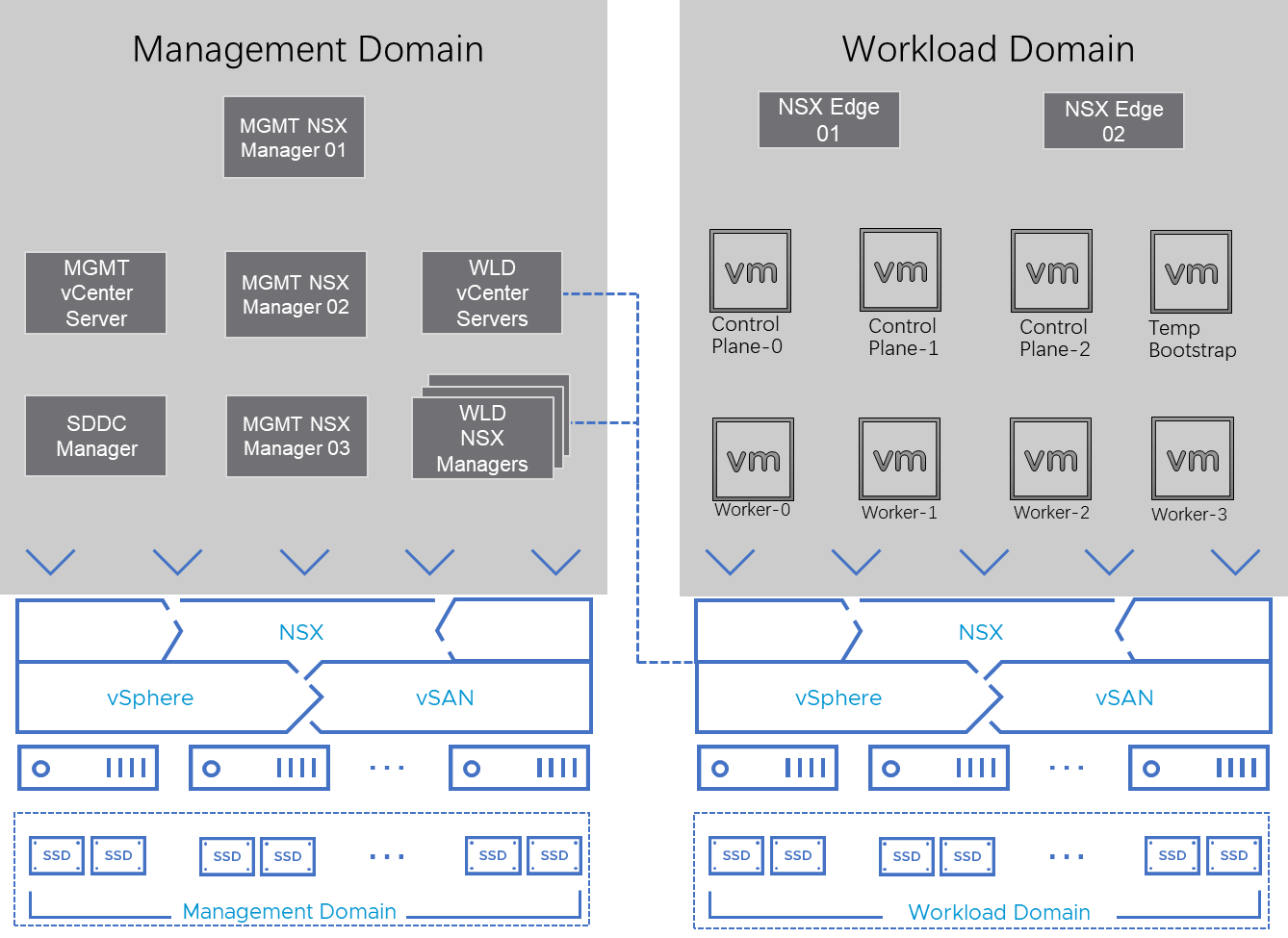
Figure 1. OpenShift on VMware Cloud Foundation Solution Standard Architecture
Notation in Figure 1:
- Temp Bootstrap: This is the temporary bootstrap node. It only exists during the installation process and will be deleted after the OpenShift Container Platform is fully deployed.
- Control plane-0,1,2: These are the control plane nodes of Kubernetes deployed and managed by OpenShift.
- Worker-0,1,2,3: These are the worker nodes of Kubernetes deployed and managed by OpenShift. We deployed 4 worker nodes as the starting point. More worker nodes can be added on demand through the OpenShift control plane.
The above architecture is called a VMware Cloud Foundation’s standard architecture.
Note: Apart from the architecture in figure 1, for a small test environment, the management domain and the workload domain can be consolidated into one domain. This architecture only requires a minimum of 4 ESXi hosts, which is ideal for a small or test environment. See https://docs.vmware.com/en/VMware-Cloud-Foundation/4.4/vcf-getting-started/GUID-C6AF75AE-569C-49F8-A15E-E9A6EF9549DA.html for details about VMware Cloud Foundation Consolidated Architecture Model.
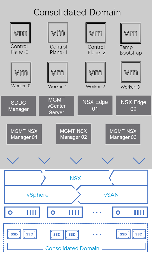
Figure 2. OpenShift on VMware Cloud Foundation Solution Consolidated Architecture
In our solution, we tested both architectures.
Standard Architecture
For the standard architecture, we created a 4-node ESXi cluster for the VMware Cloud Foundation management domain, running management virtual machines and appliances. The management domain can be shared with other workload domains.
Table 1. Management Domain VMs
| VM Role | vCPU | Memory (GB) | VM Count |
| Management Domain vCenter Server | 4 | 16 | 1 |
| SDDC Manager | 4 | 16 | 1 |
| Management Domain NSX Manager | 6 | 24 | 3 |
| Workload Domain NSX Manager | 12 | 48 | 3 |
| Workload Domain vCenter Server | 8 | 28 | 1 |
For the workload domain, we created another 4-node ESXi cluster with a separate NSX Fabric, deployed an NSX Edge Cluster, and deployed the OpenShift VMs in the workload domain.
Table 2 shows the deployment of the workload domain edge nodes and OpenShift VMs. For the workload domain edge node, we recommend that NSX Edge transport nodes are deployed with “Large” form factor.
Table 2. Workload Domain VMs
| VM Role | Minimum vCPU | Minimum Memory (GB) | Storage | Deployment Size | VM Count |
| Workload Domain Edge node | 8 | 32 | 200 GB | Large | 2 |
| OpenShift Control Plane Nodes | 4 | 16 | 120GB for OS | n/a | 3 |
| OpenShift Compute Nodes | 2 | 8 | 120GB for OS | n/a | Minimum of 2 for a standard OpenShift cluster |
| OpenShift Bootstrap Node (Temporary) | 4 | 16 | 120GB for OS | n/a | 1 |
Consolidated Architecture
For consolidated architecture, the virtual machines and their roles are the same. The difference is that in consolidated architecture, there is only one cluster consisting of four ESXi hosts, and all virtual machines are in this cluster.
The above solution architecture as shown in figure 1 and figure 2, either in Standard Architecture Model or Consolidated Architecture Model, is called a building block for a basic installation of OpenShift with VMware Cloud Foundation. Based on the customer demands and database size, we can expand the workload domain to include more physical hosts. A cluster with vSAN enabled supports up to 64 physical hosts for non-stretched cluster. With adding more hosts to the vSAN cluster, not only the capacity of CPU and memory is increased for computing but also the capacity of vSAN storage is increased accordingly. This is one of the benefits of HCI that we can increase the capacity of computing and storage at the same time and proportionally.
Hardware Resources
In this solution, for the workload domain of OpenShift, we used a total of four Dell R630 nodes. Each server was configured with two disk groups, and each disk group consisted of one cache-tier write-intensive SAS SSD and four capacity-tier read-intensive SAS SSDs.
Each ESXi node in the cluster had the following configuration, as shown in table 3.
Table 3. Hardware Configuration for Workload Cluster
| PROPERTY | SPECIFICATION |
|
Server model name |
Dell PowerEdge R630 |
| CPU | 2 x Intel(R) Xeon(R) Gold 6148 CPU @ 2.40GHz, 28 core each |
| RAM | 512GB |
| Network adapter | 2 x Broadcom BCM57414 NetXtreme-E 25Gb RDMA Ethernet Controller |
| Storage adapter | 1 x Dell HBA330 Adapter |
| Disks | Cache - 2 x 800GB Write Intensive SAS SSDs Capacity - 8 x 3.84TB Read Intensive SAS SSDs |
Software Resources
Table 4 shows the software resources used in this solution.
Table 4. Software Resources
| Software | Version | Purpose |
| VMware Cloud Foundation | 4.5 |
A unified SDDC platform that brings together VMware vSphere, vSAN, NSX, and optionally, vRealize Suite components, into a natively integrated stack to deliver enterprise-ready cloud infrastructure for the private and public cloud. See BOM of VMware Cloud Foundation for details. We used VMware Cloud Foundation 4.5 in this solution, later version is also supported. See Preparing to install on vSphere for VMware vSphere infrastructure requirements. |
| VMware vSphere | 7.0.3 | VMware vSphere is a suite of products: vCenter Server and ESXi. |
| VMware vSAN | 7.0.3 | vSAN is the storage component in VMware Cloud Foundation to provide low-cost and high-performance next-generation HCI solutions. |
| NSX Data Center | 3.2 | NSX Data Center is the key network component in VMware Cloud Foundation and is deployed automatically. It is designed for networking management and operation. |
| OpenShift | 4.10 | The version of OpenShift software being tested in this solution. See OpenShift Container Platform for the latest release introduction. |
VMware Cloud Foundation Installation
The key steps for VMware Cloud Foundation installation are as follows:
- Deploy a management domain.
- Add ESXi hosts into the system.
- Create a workload domain with the idle ESXi hosts.
Follow the official document for the detailed information about VMware Cloud Foundation installation steps.
After the installation, just make sure that NSX and vSAN are successfully enabled on this workload domain. NSX and vSAN are integrated in this solution and will be used in successive configuration of OpenShift.
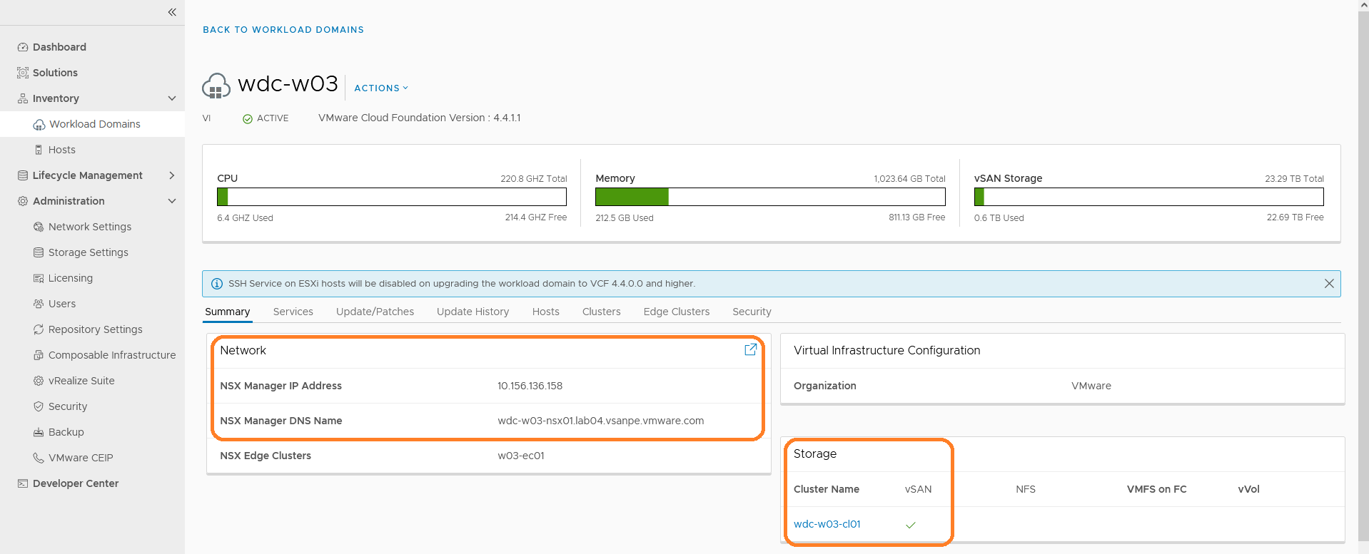
Figure 3. Check the Configuration and State of VMware Cloud Foundation Deployment
Workload Domain Preparation
After the workload domain is created for OpenShift, NSX Managers are deployed in the Management Domain. However, the NSX Edge cluster in not deployed by default.
We must add an edge cluster after the workload domain is created, as shown in Figure 3.
After the edge cluster is deployed, the state should be ‘active’ and the edge nodes’ names are also shown as in Figure 3.
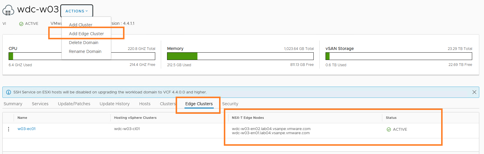
Figure 4. Enable NSX Edge Cluster on the Workload Domain
Network Configuration
Figure 5 shows the VMware vSphere Distributed Switch™ network configuration for OpenShift cluster in the workload domain of the VMware Cloud Foundation. NSX, which underlies the vSphere infrastructure, is used for the OpenShift cluster networking. To enable external access for the OpenShift cluster, an NSX Edge cluster is required to deploy. Also, it is required to configure the BGP peering and route distribution of the upstream network. For more details, refer to VMware’s NSX document.
- The ‘VCF-xxxx-External-1’ and External-2 port groups are created by VMware Cloud Foundation automatically for NSX.
- The ‘xxxx-management’, ‘xxxx-vsan, ‘xxxx-vmotion’ are also created by VMware Cloud Foundation automatically. They are used for management, vSAN and vMotion separately.
- The ‘ocp-v-c2-segment’ is a logical switch manually created in the NSX. It is used for OpenShift VM nodes.
For the management domain, the port groups are similar. For each domain, two 10 GbE vmnics were used and configured with teaming policies. The management domain can be shared among different workloads.
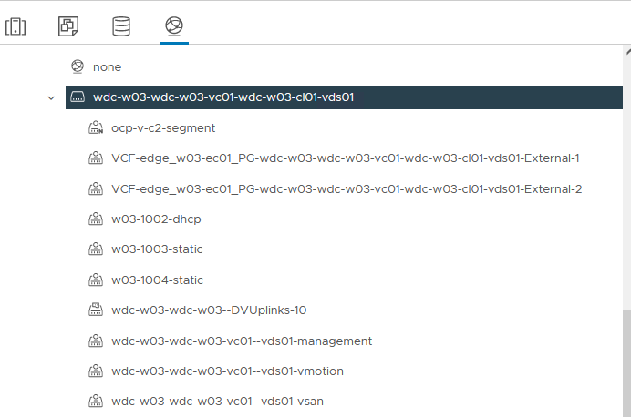
Figure 5. vSphere Distributed Switch Network Configuration
Follow the NSX Container Plugin for OpenShift -Installation and Administration Guide to create necessary NSX components, such as tier-0 and tier-1 routers.
After creation, the overall network topology is shown in Figure 6.
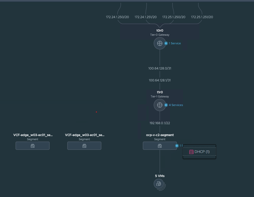
Figure 6. The Overall NSX Networking Architecture
The NSX controllers resided in the management domain. In our case, the OpenShift virtual machines were configured with a VM network called ‘ocp-v-c2-segment’ on an NSX segment. DHCP is enabled on this segment, which is required by OpenShift. VMware vSphere vMotion®, vSAN, and VXLAN VTEP for NSX had another dedicated segment created.
Jumbo Frame (MTU=9000) was enabled on the physical switches, vSAN VMkernel, and all the virtual switches to improve performance.
NSX Managers and Edges have more than one instance to form NSX clusters to achieve HA and better load balancing. Besides, based on workloads, the vCPU and memory may be adjusted to achieve better performance. Table 5 shows the configuration of the NSX managers and edge nodes virtual machines. The NSX managers reside in the management workload domain, so it will not cost the compute resources for OpenShift VMs. However, the NSX edge nodes reside in the OpenShift workload domain, and it will cost some CPU and memory resources. This should be taken into consideration while doing the sizing of the cluster before OpenShift is deployed.
Table 5. NSX Data Center VM Configuration
| nsx data center VM Role | INSTANCE | vCPU | memory (GB) | vm name | Virtual disk size | Operating System |
| NSX Manager | 3 | 12 | 48 | NSX-unified-appliance-<version> | 200GB | Ubuntu |
| NSX Edge Nodes | 2 | 4 | 8 | Edge-<UUID> | 120GB | Ubuntu |
vSAN Configuration
The solution validation was based on a 4-node vSAN cluster as a building block.
The validation tests were conducted using the default vSAN datastore storage policy of RAID 1 FTT=1, checksums enabled. The vSAN cluster has deduplication and compression deactivated, and no encryption. In the below sections, we explained the detailed configurations of the vSAN cluster and some items in the Storage Policy Based Management (SPBM).
Deduplication and Compression
The ‘Deduplication and Compression’ option was configured on the cluster level and it can be enabled or deactivated for the whole vSAN cluster. While in our testing we deactivated it, by enabling it we can reduce the vSAN storage usage but induce higher latencies for the OpenShift application. This is a tradeoff for customers’ choices.
Failures to Tolerance (FTT)
Failures to Tolerance (FTT) is a configuration item in vSAN’s storage policy. For the ‘StorageClass’ in OpenShift and the corresponding vSAN’s storage policy, we recommended setting vSAN’s Failures to Tolerate (FTT) to 1. In our testing, we set FTT to 1 as the baseline. Do not set the FTT to 0 in an OpenShift with vSAN deployment because FTT=0 may possibly cause the data of the replications of the same pod to be stored in the same physical disk. This may cause data loss in case of a physical disk failure.
In the case of using RAID 1 in vSAN policy, there are two copies for each piece of data in vSAN. So, the estimated database capacity requirement should not exceed half of the vSAN’s overall capacity. In the case of RAID 5, vSAN consumes 1.33 times of the raw capacity and you can calculate the storage usage accordingly. If the capacity increase is needed, the additional machines can be added to the cluster and vSAN can increase the data capacity storage for OpenShift online without the service interruption to OpenShift users.
Erasure Coding (RAID 1 vs. RAID 5)
Erasure Coding is a configuration item in vSAN’s storage policy. It is also known as configuring RAID 5 or RAID 6 for vSAN objects. With FTT=1 and RAID 1, the data in vSAN is mirrored and the capacity cost would be 2 times of the raw capacity. With FTT=1 and RAID 5, the data is stored as RAID 5 and the capacity cost would be 1.33 times of the raw capacity.
In our testing, we used FTT=1 without Erasure Coding (RAID 1). By enabling Erasure Coding, we could save some vSAN storage spaces but induce higher latencies for the Kubernetes applications. Again, this is a tradeoff for customers’ choices.
OpenShift Installation
There are two methods to install OpenShift on vSphere: ‘User Provisioned Infrastructure’ (UPI) and Installer-Provisioned Infrastructure (IPI). IPI is an easier way for installation as it has more automation during deployment and follow-up management.
As of OpenShift version 4.10, which is used in this reference architecture, IPI is fully supported for installing OpenShift on VMware Cloud Foundation. IPI is fully compatible with all the software components such as vSphere, Cloud Native Storage (CNS) and VMware NSX Container Plugin (NCP).
During the installation process, we mainly used this OpenShift documentation and NSX Container Plugin for OpenShift - Installation and Administration Guide for reference.
We will demonstrate the major steps and highlights in this reference architecture while the above documents have more detailed information about the explanation of each step.
With IPI installation, OpenShift installer creates virtual machines automatically in the vSphere cluster. There is no need for manually creating virtual machines.
For the network configuration, the sample customized NCP operator installation YAML files are in this Github page for reference.
The major steps are:
- In NSX Data Center, create the corresponding networking resources. With VMware Cloud Foundation, the edge cluster and overlay transport zones are already created. We do not need to manually create them again.
We need to manually create the following resources:
- A Tier-0 router
- A Tier-1 router
- A segment, for example, named ‘ocp-segment’
- An IP Block for Kubernetes Pods
- An External IP Pool
- Create a Linux virtual machine as the client, such as RHEL 8. We recommend connecting this client to the same segment as OpenShift nodes, ‘ocp-segment’ in our example. On this client, prepare the following basic software:
- Obtaining the installation program from the Infrastructure Provider page
- Navigate to the OpenShift Container Platform downloads page on the Red Hat Customer Portal. Then download the OpenShift v4.10 Linux Client entry and save the file.
- Install a text editor such as Vim.
- Install an ssh client such as openssh-client.
- On this Linux Client machine for OpenShift, create the install-config.yaml file.
The command is:
./openshift-install create install-config –dir ./
The required information is very simple as shown in figure 7.

Figure 7. Create the install-config.yaml file for OpenShift
- Pay attention to that in the OpenShift YAML file configuration above. Instead of the default ‘OpenshiftSDN’ networking method, we should specify ‘ncp’ as the networking type like the following:
networking:
networkType: ncp
clusterNetwork:
- cidr: 10.4.0.0/16
hostPrefix: 23
machineCIDR: 10.114.16.0/24
serviceNetwork:
- 172.30.0.0/16
- Run the following command to create manifests’ YAML files from the install-config.yaml file.
```
./openshift-install create manifests --dir ./
```
- The NCP YAML files are included in the NCP download file from download.vmware.com. You can go to https://github.com/vmware/nsx-container-plugin-operator/releases, find the corresponding operator release (for example, v3.1.1) and download openshift4.tar.gz.
- Extract the YAML files package:
$ tar xzvf openshift4.tar.gz
- Modify the YAML file for the NCP operator, as described in the official documentation. We only need to modify the following two files:
- configmap.yaml – Update this file with the NSX information.
- operator.yaml – Specify the NCP image location in this file.
- For configmap.yaml, modify the following parameters according to your environment:
clusternsx_api_managersnsx_api_usernsx_api_passwordexternal_ip_poolstier0_gatewayoverlay_tzedge_clusterapiserver_host_ipapiserver_host_port
- In operator.yaml, you must specify the location of NCP operator image location in the env section and NCP image in the ‘NCP_IMAGE’ environment variable.
- For the NCP Operator image, the default location is from docker hub. We recommend to pull the image and upload it to a private registry.
- For the NCP image, download it from https://downloads.vmware.com -> NSX Data Center Product Page, then find it in the “Drivers & Tools” table. After manually downloading it, also upload it to a private registry.
These locations are in bold in the following example.
kind: Deployment
metadata:
name: nsx-ncp-operator
namespace: nsx-system-operator
spec:
replicas: 1
selector:
matchLabels:
name: nsx-ncp-operator
template:
metadata:
labels:
name: nsx-ncp-operator
spec:
hostNetwork: true
serviceAccountName: nsx-ncp-operator
tolerations:
- effect: NoSchedule
key: node-role.kubernetes.io/master
- effect: NoSchedule
key: node.kubernetes.io/not-ready
containers:
- name: nsx-ncp-operator
# Replace this with the built image name
image: vmware/nsx-container-plugin-operator:latest
command: ["/bin/bash", "-c", "nsx-ncp-operator --zap-time-encoding=iso8601"]
imagePullPolicy: Always
env:
- name: POD_NAME
valueFrom:
fieldRef:
fieldPath: metadata.name
- name: OPERATOR_NAME
value: "nsx-ncp-operator"
- name: NCP_IMAGE
value: "{NCP Image}"
- Copy the NCP operator configuration files to the OpenShift’s manifests’ folder, generated in step 7,8,9 above.
cp openshift4/*.yaml manifests/
- Create the OpenShift cluster.
./openshift-install create cluster --dir ./ --log-level=debug
In this way, we can use NSX and NCP.
Some other configurations during the installation include the following key points:
DHCP
We must use DHCP in the vSphere cluster for the OpenShift cluster. Besides, we must make sure that the allocated IP addresses for virtual machines are persistent across rebooting or maintenance.
Since we used NSX in this reference architecture, turn on ‘DHCP’ service in the NSX segment for OpenShift.
Static IP Addresses
An installer-provisioned vSphere installation requires two static IP addresses:
- The API address is used to access the cluster API.
- The Ingress address is used for cluster ingress traffic.
DNS Server
We must have access to the DNS server and create two DNS records in the server for the API and Ingress IP addresses.
Table 4. DNS Server Components
|
Component |
Record |
Description |
|
API VIP |
api.<cluster_name>.<base_domain>. |
This DNS A/AAAA or CNAME record must point to the load balancer for the control plane machines. This record must be resolvable by both clients external to the cluster and from all the nodes within the cluster. |
|
Ingress VIP |
*.apps.<cluster_name>.<base_domain>. |
A wildcard DNS A/AAAA or CNAME record that points to the load balancer that targets the machines that run the Ingress router pods, which are the worker nodes by default. This record must be resolvable by both clients external to the cluster and from all the nodes within the cluster. |
See Installing a Cluster on vSphere for detailed information.
With VMware Cloud Foundation, Cloud Native Storage (CNS) is already enabled by default. There is no need for manually install CNS or install any third-party CSI driver. The CSI driver is shipped with OCP by default and it is used in this solution.
Solution Validation
Test Tools
We leveraged the following monitoring tools in this solution.
vSAN Monitoring Tools
vSAN Performance Service
vSAN Performance Service is used to monitor the performance of the vSAN environment through the vSphere Client. The performance service collects and analyzes performance statistics and displays the data in a graphical format. You can use the performance charts to manage your workload and determine the root cause of the problems.
vSAN Health Check
vSAN Health Check delivers a simplified troubleshooting and monitoring experience of all things related to vSAN. Through the vSphere client, it offers multiple health checks specifically for vSAN including cluster, hardware compatibility, data, limits, and physical disks. It is used to check the vSAN health before the mixed-workload environment deployment.
Application Validation Tools
Redis
Redis is an in-memory data structure store, used as a distributed, in-memory key–value database, cache and message broker, with optional durability. Redis supports different kinds of abstract data structures, such as strings, lists, maps, sets, sorted sets, HyperLogLogs, bitmaps, streams, and spatial indices.
For data persistent in Redis deployment with Kubernetes, a persistent volume claim needs to be created, Thus, it is a prerequisite to test the Cloud Native Storage usage.
We used Redis as one of the applications for OpenShift’s functional validation.
Functional Testing
Installation Validation
During the cluster bootstrap process, we can try some ‘kubectl’ commands to validate how the pods are created and whether the cluster is completely installed or not.
To monitor the installation status during bootstrap, ssh into the temporary bootstrap virtual machine:
$ ssh core@<bootstrap.ocp-v-c1.xxx.com>
Then, use the root user to monitor:
$ sudo su –
# kubectl --kubeconfig=/opt/openshift/auth/kubeconfig get po --all-namespaces
For example, we can check if all the pods are running without error. Some of the pods are already running and some are still under the creation stage.
Note: Due to version difference, the pods may vary.
The sample pods include the following:
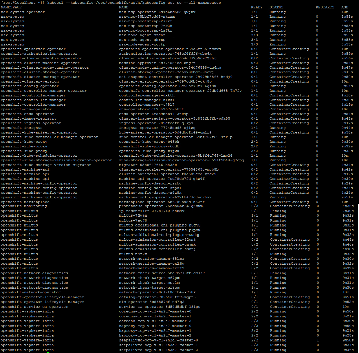
Figure 8. Monitoring the Pods’ Creation Status during Cluster Bootstrap
Then, go back to the installation client virtual machine.
After a while, when the OpenShift Container Platform is successfully installed, the command line tool will automatically show the following information, including how to access the cluster.
INFO Install complete!
INFO To access the cluster as the system:admin user when using 'oc', run 'export KUBECONFIG=/home/vmware/ocp/auth/kubeconfig'
INFO Access the OpenShift web-console here: https://console-openshift-console.apps.ocp-v-c1.xxx.com
INFO Login to the console with user: "kubeadmin", and password: "xxxx"
INFO Time elapsed: 33m14s
After successfully installing OpenShift, we can run some simple ‘oc’ commands to check if OpenShift is running healthily.
For example:
$ oc get nodes
The result is:
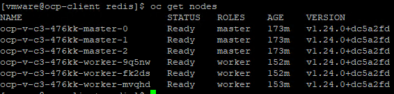
It means there are 3 control plane nodes and 3 worker nodes, and they are ready.
Application Deployment Validation
After the OpenShift Container Platform was installed, we deployed a sample Redis application which has persistent volume claim (PVC). So, we can validate that OpenShift can successfully provision an application and create PVC through CNS backed by vSAN.
There are two ways to deploy the sample Redis application:
- Deploy Redis Operator through OpenShift Web Console.
- Deploy Redis though command line tool with YAML configuration files.
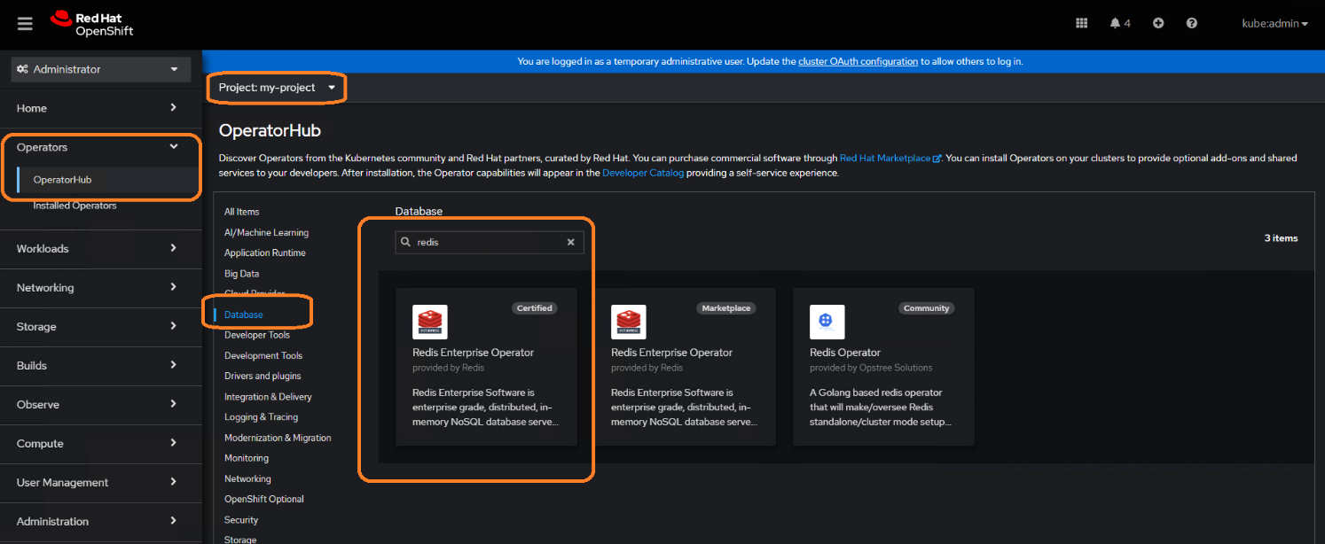
Deploying Redis Operator through the OpenShift Web Console
Key steps are:
Log in with the credentials provided during installation:
INFO Login to the console with user: "kubeadmin", and password: "xxxx"
- Look for the Redis operator:
- After the operator is installed, edit the configuration files.
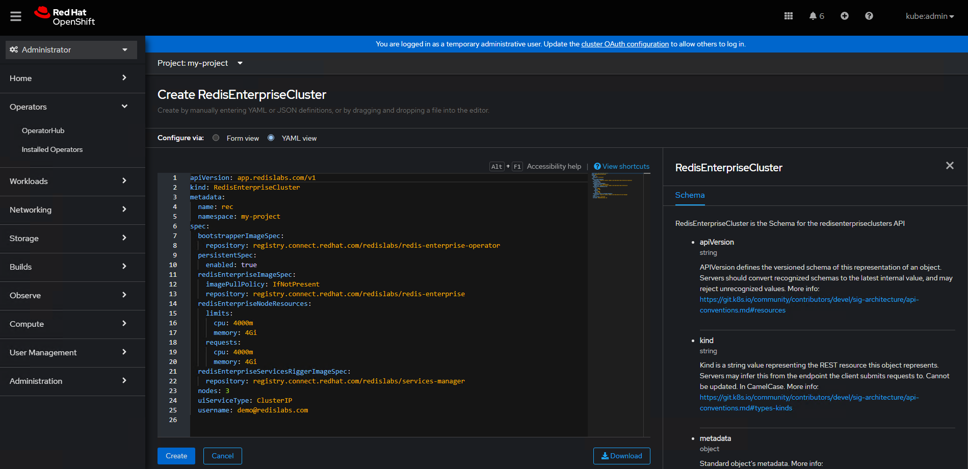
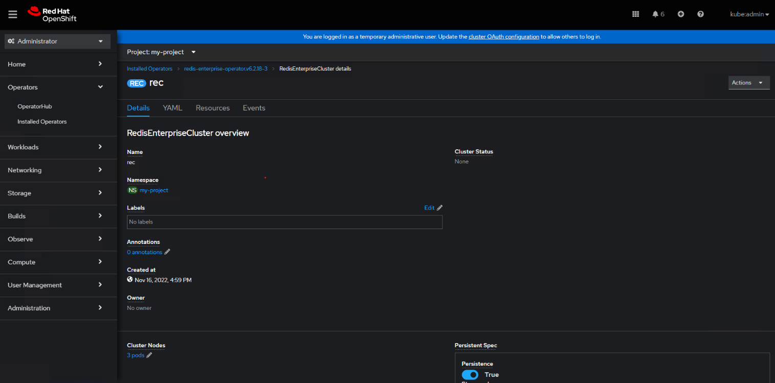
- Validate that Redis is successfully deployed.
Deploy Redis through command line tool with YAML configuration files.
Redis has an approved operator in OpenShift’s OperatorHub. However, for other applications, if there is no available operator, we can also deploy an application through YAML configuration files. We take this sample Redis deployment as an example.
Key steps are:
- Create namespace:
$ kubectl create ns redis
- Create a storage class which uses the vSAN’s RAID5 Storage Policy.
NOTE: The RAID5 Storage Policy is just a showcase to explain how to create a storage class in OCP with vSAN. We can define different policies in vSAN to meet different applications’ requirements. Then, storage classes can be created here which are backed by different storage policies in vSAN.
$ kubectl apply -f vsan-raid5-sc.yaml
A sample vsan-raid5-sc.yaml is
apiVersion: storage.k8s.io/v1
kind: StorageClass
metadata:
name: vsan-raid5-sc
annotations:
storageclass.kubernetes.io/is-default-class: "false"
provisioner: csi.vsphere.vmware.com
parameters:
storagePolicyName: “vSAN-raid5-policy”
datastore: vSANDatastore
diskformat: thin
- Create a persistent volume claim:
$ kubectl apply -f pvc.yaml
A sample pvc.yaml is:
apiVersion: v1
kind: PersistentVolumeClaim
metadata:
name: fileserver-claim
spec:
accessModes:
- ReadWriteOnce
storageClassName: "vsan-raid5-sc"
volumeName: fileserver
resources:
requests:
storage: 1G
- Deploy Redis:
$ kubectl apply -f redis.yaml
A sample Redis Pod configuration YAML file is:
apiVersion: v1
kind: Pod
metadata:
name: redis-leader
labels:
app: redis
spec:
containers:
- name: leader
image: harbor-repo.vmware.com/dockerhub-proxy-cache/redis
env:
- name: LEADER
value: "true"
volumeMounts:
- mountPath: /mnt/fileserver
name: redis-pvc
ports:
- containerPort: 6379
volumes:
- name: redis-pvc
persistentVolumeClaim:
claimName: fileserver-claim
readOnly: false
After the PVC is successfully created, we can find the corresponding PV entry in Cloud Native Storage monitoring page in vSphere client as shown in figure 8.
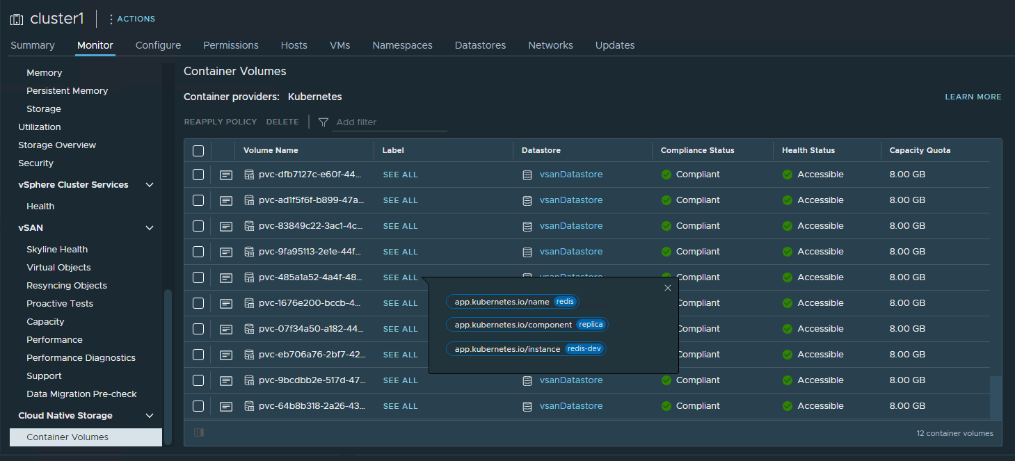
Figure 8. PVC Validation in Cloud Native Storage Monitoring Page in vSphere Client
Failure Testing
This section introduces the failure scenarios and the behavior of failover and failback. This section includes:
- Physical host failure
- Physical cache disk failure
- Physical capacity disk failure
These are related to vSAN storage functional testing under hardware failure scenarios. Under each failure condition, we saw data in vSAN stay intact and no data is lost. For more detailed information, refer to vSAN Operations Guide.
Best Practices
vSAN Best Practices
- Enable Jumbo Frame on the physical switches. Use Jumbo Frames on the vSAN VMKernel and all virtual switches.
- Apply vSAN default storage policy or with higher Failures to Tolerate (FTT) value depending on the business data protection needs.
vSphere Best Practices
- Enable vSphere HA in the cluster.
We recommend enabling vSphere High Availability for the workload domain cluster.
If vSphere HA is enabled, in case of a physical host failure and there are enough remaining resources to satisfy the resource reservation like having a spare host, vSphere can automatically power on the impacted virtual machines on the other surviving hosts.
In case of a physical host failure and if there are not enough remaining resources to satisfy the resource reservation, vSphere HA would not restart the impacted virtual machines, which is by design. Because forcing a virtual machine restart on a surviving host may cause resource contention and imbalanced performance among the OpenShift nodes. We suggest that the resource reservation should at least be set to all the control plane nodes.
- Enable vSphere DRS in the cluster
- “Fully Automated” option is configured in the DRS automation configuration.
- Place the control plane nodes on three different physical hosts to accommodate one host failure. DRS Anti-Affinity rules should be applied to separate the VMs to different physical hosts.
- Leverage DRS to automatically place the compute node virtual machines.
For DRS Anti-Affinity rules, see the DRS documentation.
- Disable vSphere storage DRS in the cluster
- vSphere storage DRS in not supported for OpenShift Container Platform. So, disable vSphere storage DRS in the cluster.
- Use compute-only vMotion and do not use Storage vMotion
- OpenShift Container Platform generally supports compute-only vMotion.
- Storage vMotion of the vSphere volumes used by pods is not supported.
Other Recommendations
- Use the same server model for the physical hosts in the workload domain.
- Follow the guidelines from OpenShift documentation for the detailed deployment and optimization items.
- Follow the NCP documentation for the NCP installation and configuration.
Conclusion
VMware Cloud Foundation delivers flexible, consistent, secure infrastructure and operations across private and public clouds. It is ideally suited to meet the demands of modern applications running on Red Hat OpenShift Container Platform in a virtualized environment.
With VMware Cloud Foundation, we can easily manage the lifecycle of the hybrid cloud environment. Besides, we have a unified management plane for all applications including OpenShift. With VMware Cloud Foundation, we can leverage the leading virtualization technologies including vSphere, NSX, and vSAN.
In this solution paper, we demonstrated the architecture of running Red Hat OpenShift Container Platform with VMware Cloud Foundation. We showed the configuration details, the hardware resources, and the software resources used in the solution validation. We showed the various configuration options in addition to the best practices. VMware Cloud Foundation Manager provided the lifecycle management. vSAN provides reliable, high-performance, and flexible storage to OpenShift. NSX Data Center provided the fine-grained, secured, and high-performance virtual networking infrastructure to OpenShift. Also, vSphere DRS and vSphere HA provided efficient resource usage and high availability. All the above lead to a consolidated solution of running Red Hat OpenShift Container Platform with VMware Cloud Foundation.
References
About the Author
Victor (Shi) Chen, Sr. Technical Marketing Manager of the Workload Technical Marketing team, wrote the original version of this paper.
The following reviewers also contributed to the paper contents:
- Chen Wei, Director of the Workload Technical Marketing team in VMware
- Ka Kit Wong, Staff Technical Marketing Architect of the Workload Technical Marketing team in VMware
- Catherine Xu, Senior Manager of the Workload Technical Marketing team in VMware
- Gregory Charot, Senior Principal Product Manager in Red Hat
- Vivien Wang, Ecosystem Partner Manager in Red Hat
- Mike Guerette, Principal Product Marketing Manager in Red Hat
- Ju Lim, Senior Manager, Product Management in Red Hat
- Hemant Kumar, Principal Software Engineer in Red Hat
- Ramon Acedo Rodriguzez, Senior Principal Product Manager in Red Hat