
Tanzu Proof of Concept Guide_Prev
POC Guide Overview
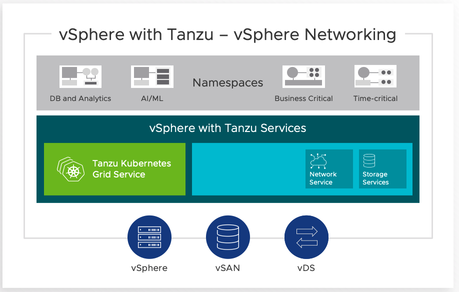
This POC Guide is intended to test use cases on both vSphere with Tanzu as well as VMware Cloud Foundation (VCF) with Tanzu.
The fastest way to get started with Kubernetes workloads is with vSphere with Tanzu. From vSphere 7 Update 1, Tanzu Kubernetes can be enabled without NSX. In contrast, VMware Cloud Foundation (VCF) provides a hybrid cloud platform that allows for an automated deployment of NSX and Tanzu components.
The advantages from the VCF approach include the ability to scale out quickly and efficiently, providing an enterprise-ready infrastructure deployment model. This, together with the proven technologies of NSX, mean that VCF is the go-to solution for many organizations.
However, for smaller environments, or where organizations are not yet ready for a full-scale deployment of a hybrid cloud, the leaner footprint of vSphere with Tanzu may be more appealing. Starting with vSphere 7.0 Update 1, getting a Kubernetes environment within vSphere is now simpler than ever.
vSphere with Tanzu Overview and Setup
Overview
Getting Started
The basic steps and requirements to get started with vSphere with Tanzu are shown below. For more details, please refer to the quick start guide:
https://core.vmware.com/resource/vsphere-tanzu-quick-start-guide
For Kubernetes network services, vSphere with Tanzu allows you to bring your own network solution. Here, we will use the open-source HaProxy solution (for more details visit haproxy.org).
VMware have packaged HaProxy in a convenient OVA format, which can be downloaded and deployed quickly. This is hosted on GitHub: https://github.com/haproxytech/vmware-haproxy
In the simplest configuration, the HA Proxy appliance will need a minimum of two interfaces, one on the ‘Management’ network and the other on a ‘Workload’ network, with a static IP address in each. (An option to deploy with three networks, i.e., with an additional ‘Frontend’ network is also available but is beyond the scope of this guide).
Below we will go through the basic setup of HaProxy and enabling Workload Management to quickly get started.
Network Requirements
In vCenter, configure a DVS with at least two portgroups for ‘Management’ and ‘Workload Network’.
The following IP addresses are required:
Management Network:
5x consecutive routable IP addresses for Workload Management, plus one for HaProxy
Workload Network:
For simplicity, one /24 routable network (which will be split into subnets). In the example below, we will use the network 172.168.161.0/24 with 172.168.161.1 as the gateway.
HaProxy Configuration
Download and configure the latest HaProxy OVA from the GitHub site.
Here, we will use the ‘Default’ configuration, which will deploy the appliance with two network interfaces:

The two portgroups for Management and Workload Network should be populated with the appropriate values. The Frontend network can be ignored:

Use the following parameters as a guide, substituting the workload network for your own.
As per the table below, we subnet the Workload network to a /25 for the load-balancer IP ranges in step 3.1. In addition, the HaProxy will require an IP for itself in the workload network.
|
1.2 |
Permit Root Login |
True |
|
2.1 |
Host Name |
<Set a Host Name> |
|
2.2 |
DNS |
<DNS Server> |
|
2.3 |
Management IP |
<IP in Mgmt range> |
|
2.4 |
Management Gateway |
<Mgmt Gateway> |
|
2.5 |
Workload IP |
172.168.161.3 |
|
2.6 |
Workload Gateway |
172.168.161.1 |
|
3.1 |
Load Balancer IP Ranges (CIDR) |
172.168.161.128/25 |
|
3.2 |
Dataplane API Management Port |
5556 |
|
3.3 |
HaProxy User ID |
admin |
|
3.4 |
HaProxy Password |
<set a password> |
N.B.: Take special care with step 3.1, this must be in CIDR format. Moreover, this must cover the “IP Address Ranges for Virtual Servers” which will be used later to enable Workload Management in vCenter (see below). Note that the vCenter wizard will require the range defined here in a hyphenated format: from the example above, 172.168.161.128/25 covers the range 172.168.161.129-172.168.171.240
TKG Content Library
Before we can start the Workload Management wizard, we need to first setup the TKG Content Library to pull in the TKG VMs from the VMware repository. The vCenter where the TKG content library will be created on should have internet access in order to be able to connect to the repo.
Create a subscribed content library (Menu > Content Libraries > Create New Content Library) pointing to the URL: https://wp-content.vmware.com/v2/latest/lib.json

For the detailed procedure, see the documentation: https://via.vmw.com/tanzu_content_library
Configure Workload Management
After the HaProxy appliance has been configured successfully, log into it using SSH. List the contents of the file /etc/haproxy/ca.crt, which will be used in the steps below.
In vCenter, ensure that DRS and HA are enabled and a storage policy for the control plane VMs exists. In a vSAN environment, the default vSAN policy can be used.
Navigate to Menu > Workload Management to start the wizard. Below we’ll focus on the networking steps (for further details, see the Quick Start guide):
Use the following as a guide, again, replacing values for your own:
5. Load Balancer:
Name*: lb1
Type: HA Proxy
Data plane API Address(s): <HaProxy mgmt IP>:5556
Username: admin
Password: <password from haproxy appliance>
IP Address Ranges for Virtual Servers^: 172.168.161.129–172.168.171.240
Server Certificate Authority: <contents of the file /etc/haproxy/ca.crt>
* Note that this is a Kubernetes construct, not the DNS name of the HaProxy appliance.
^ This must be within the CIDR range defined in step 3.1 of the HaProxy configuration
6. Management Network:
Network: <mgmt port group>
Starting IP: <first IP of consecutive range>
Subnet: <mgmt subnet>
Gateway: <management gateway>
DNS: <dns server>
NTP: <ntp server>
7. Workload Network:
Name: <any you choose>
Port Group: <workload port group>
Gateway: 172.168.161.1
Subnet: 255.255.255.0
IP Address Ranges*: 172.168.161.20–172.168.161.100
* These must not overlap with the load-balancer addresses
For more details, the Quick Start guide will guide you through the detailed setup and configuration of both the HaProxy appliance and the vSphere configuration.
VCF with Tanzu Overview and Setup
Overview
VCF utilizes NSX to provide enterprise-class networking with automated workflows to deploy at scale. NSX provides a container plug-in (NCP) that interfaces with Kubernetes to automatically serve networking requests (such as ingress and load balancer) from NSX Manager. For more details on NCP, visit: https://via.vmw.com/ncp.
For a detailed description on networking in a Tanzu requirements see: https://via.vmw.com/tkc-networking
In addition, VCF with Tanzu provides two further elements: ‘vSphere Pods’ and a built-in vSphere registry based on Harbor. The vSphere Pod service enables services from VMware and partners to run directly on top of ESXi hosts, providing a performant, secure and tightly integrated Kubernetes environment.
For more details on vSphere Pods see https://via.vmw.com/vsphere_pods and https://blogs.vmware.com/vsphere/2020/04/vsphere-7-vsphere-pod-service.html

Once the VCF environment with SDDC manager has been deployed (see https://docs.vmware.com/en/VMware-Cloud-Foundation/index.html for more details), Workload Management can be enabled. Note that both standard and consolidated deployments can be used.
Getting Started
A detailed step-by-step guide can be found in the VCF POC Guide. First, in SDDC Manager, click on Solutions, this should show “Kubernetes – Workload Management”. Click on Deploy and this will show a window with the deployment pre-requisites, i.e.:
- Hosts are licensed correctly
- An NSX-T based Workload Domain has been provisioned
- NSX Edge cluster deployed with a ‘large’ form factor
- The following IP addresses have been reserved for use:
- non-routable /22 subnet for pod networking
- non-routable /24 subnet for Kubernetes services
- two routable /27 subnets for ingress and egress
- 5x consecutive IP addresses in the management range for Supervisor services
Clicking on Begin will start the Kubernetes deployment wizard.


Select the appropriate cluster from the drop-down box. Click on the radio button next to the compatible cluster and click on Next.

The next screen will go through some validation checks
Check that the validation succeeds. After clicking on Next again, check the details in the final Review window:

Click on Complete in vSphere to continue the wizard in vCenter
Ensure the correct cluster has been pre-selected:

After clicking on Next, select the desired control plane size.
Click on Next to show the Workload Management section:

To show the Storage section, click on Next. Select the appropriate storage policies for the control plane, ephemeral disks and image cache:

Click on Next to show the review window. Clicking on Finish will start the supervisor deployment process:

For an interactive guide of the steps above, visit Tech Zone
TKG Content Library
To later setup Tanzu Kubernetes Clusters, we need to first setup the TKG Content Library to pull in the TKG VMs from the VMware repository.
Create a subscribed content library (Menu > Content Libraries > Create New Content Library) pointing to the URL: https://wp-content.vmware.com/v2/latest/lib.json
For the detailed procedure, see the documentation: https://via.vmw.com/tanzu_content_library
Supervisor Cluster Operations
After the process has been completed, navigate to Cluster > Monitor > Namespaces > Overview to ensure the correct details are shown and the health is green. Note that whilst the operations are in progress, there may be ‘errors’ shown on this page, as it is monitoring a desired state model:

Configure Supervisor Cluster Namespace(s) with RBAC
Once the supervisor cluster has been configured, a namespace should be created in order to set permissions, storage policies, and capacity limitations among others. In Kubernetes, a namespace is a collection of resources such as containers, disks, etc.
To create a namespace, navigate to Menu > Workload Management > Click on Namespaces > New Namespace. Fill in the necessary fields and click create.

The new namespace area will be presented. This is where permissions, storage policies and other options can be set.

After clicking “Got It” button, the summary will show a widget where permissions can be set.

Click on Add Permissions and fill in the necessary fields. It is important to note that the user/group to be added to this namespace should have already been created ahead of time. This can be an Active Directory user/group (see https://via.vmw.com/ad_setup) or ‘vsphere.local’:

After adding permission, the summary screen will show who has permissions and what type. Clicking the Manage Permissions link will take you to the Permissions tab for this namespace

From the permissions tab, you can add/remove/edit permissions for a particular namespace. Thus, here we can enable access for a developer to be able to consume the namespace.

Configure Supervisor Cluster Namespace(s) Storage Policy
First, configure any storage policies as needed, either by defining a VM storage policy (as is the case for vSAN) or by tagging an existing datastore. Note that vSAN comes with a default storage policy ‘vSAN Default Storage Policy’ that can be used without any additional configuration.
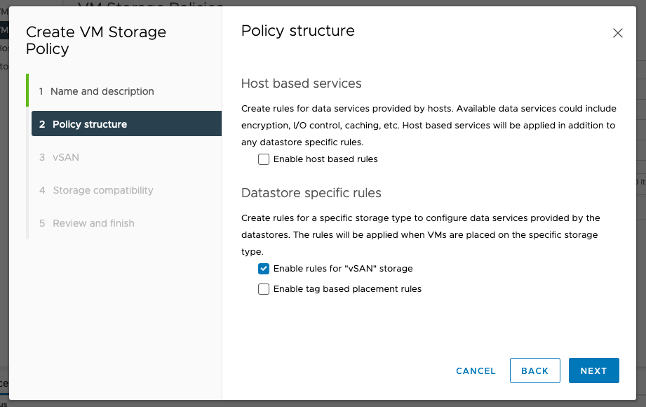
To create a VM storage policy, navigate to Menu > Policies and Profiles > VM Storage Policies and click on ‘Create’. Follow the prompts for either a vSAN storage policy or tag-based policy under “Datastore Specific rules”.
Once a Policy has been created, navigate back to the namespace and click on ‘add storage’

Select the appropriate storage policy to add to the namespace:

Configure Supervisor Cluster Namespace(s) with Resource Limitations
Resource limitations such as CPU, memory, and storage can be tied to a namespace. Under the namespace, click on the Configure tab and select Resource Limits.

By clicking on the edit button, resources can be limited for this specific Namespace. Resource limitations can also be set at the container level.

Note that under the Configure tab, it is also possible to limit objects such as Replica Sets, Persistent Volume Claims (PVC), and network services among others.

Kubernetes Operations
Whilst many of the operations in this guide can be performed on a standard end-user laptop (be it Windows, MacOS or Linux), it is a good idea to deploy a jump host VM, which has the tools and configuration ready to work with. A Linux VM is recommended.
Conveniently, there is a TKG Demo Appliance fling that we can leverage for our purposes. Download and deploy the OVA file from the link below (look for the ‘offline download’ of the TKG Demo Appliance OVA): https://via.vmw.com/tkg_demo
Once a namespace has been created (see steps above), a command-line utility (kubectl-vsphere) needs to be downloaded to be able to login to the namespace. First, navigate to the namespace in vCenter: Menu > Workload Management > Namespace then select ‘Copy link’:

This will provide the VIP address needed to login to the namespace. Make a note of this address. Then on your jump VM, download the zip file ‘vsphere-plugin.zip’, either using a browser or via wget, pointing to https://<VIP>/wcp/plugin/linux-amd64/vsphere-plugin.zip
For example:
# wget https://172.168.61.129/wcp/plugin/linux-amd64/vsphere-plugin.zip --no-check-certificate
Unzip this file and place the contents in the system path (such as /usr/local/bin). The zip file contains two files, namely kubectl and kubectl-vsphere.
To log into a namespace on the supervisor cluster, issue the following command, replacing the VIP IP with your own:
# kubectl vsphere login --server=172.168.61.129 --insecure-skip-tls-verify
Use the credentials of the user added to the namespace to login.
Note that the ‘insecure’ option needs to be specified unless the appropriate TLS certificates have been installed on the jump host. For more details see: https://via.vmw.com/tanzu_tls
Once logged in, perform a quick check to verify the health of the cluster using ‘kubectl cluster-info’:
# kubectl cluster-info
Kubernetes master is running at https://172.168.61.129:6443
KubeDNS is running at https://172.168.61.129:6443/api/v1/namespaces/kube-system/services/kube-dns:dns/proxy
To further debug and diagnose cluster problems, use 'kubectl cluster-info dump'.
Shell Tweaks (optional)
In order to have a better experience (less typing and mistakes) it’s advisable to create an alias to kubectl and setup autocomplete. The details below are for a *nix/bash environment.
For autocomplete:
# source <(kubectl completion bash)
# echo "source <(kubectl completion bash)" >> ~/.bashrc
To set the alias of kubectl to just ‘k’:
# echo "alias k='kubectl'" >> ~/.bashrc
For more details and other settings, see the kubectl cheat sheet: https://kubernetes.io/docs/reference/kubectl/cheatsheet/
Tanzu Kubernetes Cluster (TKC) Deployment
Once the supervisor cluster has been enabled, and a namespace created (as above), we can create an upstream-compliant Tanzu Kubernetes Cluster (TKC). This is done by applying a manifest on the supervisor cluster which will define how the cluster is setup.
First, login to the supervisor namespace using ‘kubectl vsphere login’ as above. If necessary, use the ‘kubectl config use-context’ command to switch to the correct supervisor namespace.
To get the contexts available (the asterisk shows the current context used):
# kubectl config get-contexts
CURRENT NAME CLUSTER AUTHINFO NAMESPACE
* 172.168.61.129 172.168.61.129 dev@vsphere.local
ns01 172.168.61.129 dev@vsphere.local ns01
And to switch between them:
# kubectl config use-context ns01
Switched to context "ns01".
If we have setup our TKC content library correctly, we should be able to see the downloaded VM images:
# kubectl get vmimage
NAME VERSION OSTYPE
vmware.1-tkg.3.60d2ffd v1.16.8+vmware.1-tkg.3.60d2ffd vmwarePhoton64Guest
vmware.1-tkg.1.154236c v1.17.7+vmware.1-tkg.1.154236c vmwarePhoton64Guest
vmware.1-tkg.1.da7afe7 v1.16.12+vmware.1-tkg.1.da7afe7 vmwarePhoton64Guest
vmware.1-tkg.1.5417466 v1.17.8+vmware.1-tkg.1.5417466 vmwarePhoton64Guest
vmware.1-tkg.1.ada4837 v1.16.14+vmware.1-tkg.1.ada4837 vmwarePhoton64Guest
vmware.1-tkg.1.c40d30d v1.18.5+vmware.1-tkg.1.c40d30d vmwarePhoton64Guest
vmware.1-tkg.1.15f1e18 v1.17.11+vmware.1-tkg.1.15f1e18 vmwarePhoton64Guest
vmware.1-tkg.2.ad3d374 v1.17.11+vmware.1-tkg.2.ad3d374 vmwarePhoton64Guest
We can also see the available Kubernetes versions using the ‘kubectl get tanzukubernetesreleases’ command, or using the shorthand ‘tkr’
# kubectl get tkr
NAME VERSION CREATED
v1.16.12---vmware.1-tkg.1.da7afe7 1.16.12+vmware.1-tkg.1.da7afe7 28d
v1.16.14---vmware.1-tkg.1.ada4837 1.16.14+vmware.1-tkg.1.ada4837 28d
v1.16.8---vmware.1-tkg.3.60d2ffd 1.16.8+vmware.1-tkg.3.60d2ffd 28d
v1.17.11---vmware.1-tkg.1.15f1e18 1.17.11+vmware.1-tkg.1.15f1e18 28d
v1.17.11---vmware.1-tkg.2.ad3d374 1.17.11+vmware.1-tkg.2.ad3d374 8d
v1.17.7---vmware.1-tkg.1.154236c 1.17.7+vmware.1-tkg.1.154236c 28d
v1.17.8---vmware.1-tkg.1.5417466 1.17.8+vmware.1-tkg.1.5417466 28d
v1.18.5---vmware.1-tkg.1.c40d30d 1.18.5+vmware.1-tkg.1.c40d30d 22d
Thus, versions from 1.16.8 through to 1.17.11 are available to use.
We then need to create a manifest to deploy the TKC VMs. An example manifest is shown below, this will create a cluster in the ns01 supervisor namespace called ‘tkgcluster1’ consisting of one control-plane and three worker-nodes, with the Kubernetes version 1.17.8:
TKG-deploy.yaml
|
apiVersion: run.tanzu.vmware.com/v1alpha1
kind: TanzuKubernetesCluster
metadata:
name: tkgcluster1
namespace: ns01
spec:
distribution:
version: v1.17.8
topology:
controlPane:
count: 1
class: guaranteed-small
storageClass: vsan-default-storage-policy
workers:
count: 3
class: guaranteed-small
storageClass: vsan-default-storage-policy
|
Let’s dissect this manifest to examine the components:
.png)
A: These lines specify the API version and the kind; these should not be modified. To get the available API version for Tanzu, run ‘kubectl api-versions | grep tanzu’.
B: Tanzu Kubernetes cluster name is defined in the field ‘name’ and the supervisor namespace is defined in the ‘namespace’ field.
C: The K8s version (v1.17.8) is defined. This will depend on the downloaded TKG VMs from the content library. Use the command ‘kubectl get tkr’ to obtain the available versions.
D: The created VMs will use the ‘guaranteed-small’ profile, for more details on the sizing see: https://via.vmw.com/tanzu_vm_classes
E: Storage policy to be used by the control plane VMs
For clarity, some fields have been omitted (the defaults will be used). For a full list of parameters, refer to the documentation: https://via.vmw.com/tanzu_params and further manifest file examples: https://via.vmw.com/tanzu_yaml
Once this file has been created, use kubectl to start the deployment, for example, we create a manifest file called ‘TKG-deploy.yaml’ and apply:
kubectl apply -f TKG-deploy.yaml
The supervisor cluster will create the required VMs and configure the TKC as needed. This can be monitored using the get and describe verbs on the ‘tkc’ noun, for example:
# kubectl get tkc -o wide
NAME CONTROL PLANE WORKER DISTRIBUTION AGE PHASE
tkgcluster1 1 1 v1.17.8+vmware.1-tkg.1.5417466 28d running
# kubectl describe tkc
Name: tkgcluster1
Namespace: ns01
Labels: <none>
Annotations: API Version: run.tanzu.vmware.com/v1alpha1
Kind: TanzuKubernetesCluster
.
.
Node Status:
tkgcluster1-control-plane-jznzb: ready
tkgcluster1-workers-fl7x8-59849ddbb-g8qjq: ready
tkgcluster1-workers-fl7x8-59849ddbb-jqzn4: ready
tkgcluster1-workers-fl7x8-59849ddbb-kshrt: ready
Phase: running
Vm Status:
tkgcluster1-control-plane-jznzb: ready
tkgcluster1-workers-fl7x8-59849ddbb-g8qjq: ready
tkgcluster1-workers-fl7x8-59849ddbb-jqzn4: ready
tkgcluster1-workers-fl7x8-59849ddbb-kshrt: ready
Events: <none>
For more verbose output and to watch the cluster being built out, select yaml as the output with the ‘-w’ switch:
# kubectl get tkc -o yaml -w
.
.
nodeStatus:
tkc-1-control-plane-lvfdt: notready
tkc-1-workers-fxspd-894697d7b-nz682: pending
phase: creating
vmStatus:
tkc-1-control-plane-lvfdt: ready
tkc-1-workers-fxspd-894697d7b-nz682: pending
In vCenter, we can see the TKC VMs being created (as per the manifest) within the supervisor namespace:
.png)
Once provisioned, we should be able to see the created VMs in the namespace:
# kubectl get wcpmachines
NAME PROVIDERID IPADDR
tkgcluster1-control-plane-scsz5-2dr55 vsphere://42107544 172.168.61.33
tkgcluster1-workers-tjpzq-gkdn2 vsphere://421019aa 172.168.61.35
tkgcluster1-workers-tjpzq-npw88 vsphere://421055cf 172.168.61.38
tkgcluster1-workers-tjpzq-vpcwx vsphere://4210d90c 172.168.61.36
Once the TKC has been created, login to it by using ‘kubectl vsphere’ with the following options:
# kubectl vsphere login –server=<VIP> \
--insecure-skip-tls-verify \
--tanzu-kubernetes-cluster-namespace=<supervisor namespace> \
--tanzu-kubernetes-cluster-name=<TKC name>
For example:
# kubectl-vsphere login --server=https://172.168.61.129 \
--insecure-skip-tls-verify \
--tanzu-kubernetes-cluster-namespace=ns01 \
--tanzu-kubernetes-cluster-name=tkgcluster1
Login using the user/credentials assigned to the namespace. You can then change contexts between the TKC and the supervisor namespace with the ‘kubectl config’ command (as above).
TKC RBAC
See the documentation to grant developer access to the cluster: https://via.vmw.com/tanzu_rbac
This is also a requirement for some app deployments. A basic RBAC profile is shown below (this can be applied as-is to enable access for the administrator@vsphere.local account):
TKG-admin-rbac.yaml
|
apiVersion: rbac.authorization.k8s.io/v1
kind: ClusterRoleBinding
metadata:
name: all:psp:privileged
roleRef:
kind: ClusterRole
name: psp:privileged
apiGroup: rbac.authorization.k8s.io
subjects:
kind: Group
name: system:serviceaccounts
apiGroup: rbac.authorization.k8s.io
|
App Deployment and Testing
Deploy Kuard to verify setup
A very basic test to see if the K8s cluster is operational is to deploy KUARD (Kubernetes Up and Running)
Use the commands below to pull the KUARD image and assign an IP to it. (HaProxy will serve the IP from the workload subnet):
# kubectl run --restart=Never --image=gcr.io/kuar-demo/kuard-amd64:blue kuard
# kubectl expose pod kuard --type=LoadBalancer --name=kuard --port=8080
Once deployed, we can list the external IP assigned to it using the ‘get service’ command:
# kubectl get service
NAME TYPE CLUSTER-IP EXTERNAL-IP PORT(S) AGE
kuard LoadBalancer 10.96.0.136 152.17.31.132 8080:30243/TCP 6s
Therefore, opening a browser to the ‘External-IP’ on port 8080, i.e. http://152.17.31.32:8080 should give us a webpage showing the KUARD output:
.png)
Deploy Octant (optional)
Octant is a highly extensible Kubernetes management tool that, amongst many other features, allows for a graphical view of the Kubernetes environment. This is useful in a PoC environment to see the relationship between the different components. See https://github.com/vmware-tanzu/octant for more details.
If the TKG Demo Appliance is being used, Octant is already installed. Otherwise, download and install Octant, as described in the Octant getting started page:
https://reference.octant.dev/?path=/docs/docs-intro--page#getting-started
Launch Octant simply by the command ‘Octant’:
# octant &
Open an SSH tunnel port 7777 of the jump host –
For instance, from a Mac terminal:
$ ssh -L 7777:127.0.0.1:7777 -N -f -l root <jump host IP>
Or Windows, using putty -- navigate to Connection > SSH > Tunnels on the left panel. Enter ‘7777’ for the source port and ‘127.0.0.1:7777’ as the destination. Then click on ‘add’ and open a session to the jump host VM:

Thus, if we open a browser to http://127.0.0.1:777 (note http not https) we can see the Octant console:

Persistent Volume Claims (PVC)
To create a PVC, first we need to map any storage policies (defined in vCenter) we wish to use to the supervisor namespace.
First, create the storage policy in vCenter, under Menu > Policies and Profiles > VM Storage Policies. Note the convention of using lowercase names:

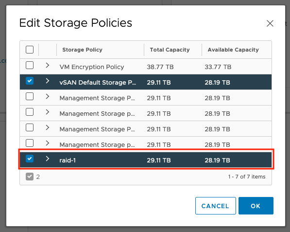
Then add them to the namespace by clicking on ‘Edit Storage’
.png)
Select any additional storage policies. In the example below, we add the new ‘raid-1’ policy:
To list all of the available storage classes, we run:
# kubectl get storageclass
NAME PROVISIONER RECLAIMPOLICY VOLUMEBINDINGMODE ALLOWVOLUMEEXPANSION
raid-1 csi.vsphere.vmware.com Delete Immediate true
We can then create a PVC using a manifest. In the example below, we create a 2Gi volume:
2g-block-r1.yaml
|
apiVersion: v1
kind: PersistentVolumeClaim
metadata:
name: block-pvc-r1-2g
spec:
storageClassName: raid-1
accessModes:
- ReadWriteOnce resources:
requests:
storage: 2Gi
|
Then apply this:
# kubectl apply -f 2g-block-r1.yaml
To see the details:
# kubectl get pvc
NAME STATUS VOLUME CAPACITY ACCESS MODES STORAGECLASS
block-pvc-r1-2g Bound pvc-0a612267 2Gi RWO raid-1
Now we have a volume, we can create attach this to a pod. In the example below, we create a pod using Busybox and mount the volume created above:
simple-pod.yaml
|
apiVersion: v1
kind: Pod
metadata:
name: simple-pod
spec:
containers:
name: simple-pod
image: "k8s.gcr.io/busybox"
volumeMounts:
name: block-vol
mountPath: "/mnt/volume1"
command: [ "sleep", "1000000" ]
volumes:
name: block-vol
persistentVolumeClaim:
claimName: block-pvc-r1-2g
|
Once the pod has been created, we can examine the storage within it.
First, we run a shell on the pod:
# kubectl exec -it simple-pod -- /bin/sh
Using the df command, we can see the volume has been attached and is available for consumption:
# df -h /mnt/volume1/
Filesystem Size Used Available Use% Mounted on
/dev/sdb 1.9G 6.0M 1.8G 0% /mnt/volume1
Furthermore, we can see the PVCs created by a Kubernetes admin in vCenter by navigating to either Datacenter > Container Volumes or Cluster > Monitor > Container Volumes:
.png)
Clicking on the square next to the volume icon shows more information about the PVC and where it is used. From our example, we see the guest cluster, the pod name “simple pod” and the PVC name given in the manifest:
.png)
.png)
.png)
Clicking on Physical Placement shows (as we are using a vSAN store) the backing vSAN details:
.png)
We can also see details of the PVC in vCenter under Cluster > Namespaces > Namespace > Storage > Persistent Volume Claims:
.png)
Here, we can see more details – specifically Kubernetes parameters, if we click on ‘View YAML’:
.png)

Wordpress & MySQL app
The Kubernetes documentation has a practical example on using PVCs using WordPress and MySQL:
https://kubernetes.io/docs/tutorials/stateful-application/mysql-wordpress-persistent-volume/
However, the PVC claims in example manifests do not include a storage policy (which is required for the PVC to be created). To successfully deploy this app, we must either add a default storage policy into our TKC manifest or edit the manifests to define a storage policy.
Follow the steps on the demo page, taking note of the following:
- Ensure that an TKC RBAC profile has been applied to the cluster
- Create a new directory on the jump VM
- Generate the kustomization.yaml file with a password
- Download the two manifest files for mySQL and Wordpress using curl
- Add the two files to the kustomization.yaml as shown
- Follow one of the two options below to satisfy the storage policy requirement. (For the quickest solution, copy and paste the awk line in option 2)
- Option 1: Edit the TKC manifest
-
Here, we will define a default storage policy ‘defaultClass’ for our TKC cluster. First change context to the Supervisor namespace. In the example below, this is ‘ns01’:
# kubectl config use-context ns01
Then edit the tkc manifest for your TKG cluster, for instance:
# kubectl edit tkc/tkgcluster1
Add the following lines under spec/settings:
storage:
defaultClass: <storage policy>For example, we add the ‘vsan-default-storage-policy’:
spec:
distribution:
fullVersion: v1.17.8+vmware.1-tkg.1.5417466
version: v1.17.8
settings:
network:
cni:
name: antrea
pods:
cidrBlocks:
- 192.168.0.0/16
serviceDomain: cluster.local
services:
cidrBlocks:
- 10.96.0.0/12
storage:
defaultClass: vsan-default-storage-policyFor more details on editing the TKC manifest, see the documentation: https://via.vmw.com/tanzu_update_manifest
- Option 2: Edit the app manifest files
-
Add the following line to the two manifest files after the line ‘- ReadWriteOnce’
storageClassName: <storage policy>
For example:
spec:
accessModes:
- ReadWriteOnce
storageClassName: vsan-default-storage-policyWe could also use a script to add this line in to both files. For example, using awk:
# for x in $(grep -l 'app: wordpress' *); do awk '/ReadWriteOnce/{print;print " storageClassName: vsan-default-storage-policy";next}1' $x >> $x; done
After the storage policy has been set, run the following command within the directory:
kubectl apply -k ./
Once the manifests are applied, we can see that the PVC has been created:
# kubectl get pvc
NAME STATUS VOLUME CAPACITY ACCESS STORAGECLASS
mysql-pv-claim Bound pvc-6d9d 20Gi RWO vsan-default-storage-policy
wp-pv-claim Bound pvc-1906 20Gi RWO vsan-default-storage-policy
The external IP can be obtained from the service ‘wordpress’:
# kubectl get services wordpress
NAME TYPE CLUSTER-IP EXTERNAL-IP PORT(S)
wordpress LoadBalancer 10.101.154.101 172.168.61.132 80:31840/TCP
Putting that IP (in this case 172.168.61.132) into a browser should give the WordPress setup page:
.png)
Also, in vCenter, we can see that the PVC volumes have been tagged with the application name:
.png)
Delete Operations
Destroy TKC and related objects
In order to delete a Tanzu Kubernetes Cluster, first switch to the namespace where the cluster is located. Visually, this can be done from vCenter
# kubectl config use-context <workload name>
Check the namespace you are working with. A star next to the name states the currently selected context
# kubectl config get-contexts
See which TKC cluster(s) reside in the selected context
# kubectl get tkc
![]()
Prior to deletion, conduct a search for tkc-2 within the vCenter search field to see all related objects with such TKC

To the delete TKC with the name tkc-2 in this case, can be done by running the following command:
# kubectl delete tkc tkc-2
vCenter will have tasks regarding the deletion of the TKC cluster and all related objects

To check deletion is completed:
# kubectl get tkc

From vCenter, conduct another search for tkc-2

Delete Namespaces
You can easily delete Namespaces from vCenter UI.
To delete namespaces from the UI, navigate to Menu > Workload Management > Namespaces click on the namespace and click remove


Delete deployed Supervisor Cluster, confirm resources are released
The supervisor cluster gets deleted when you disable Workload Management for a specific cluster. This action will also delete any existing Namespaces and TKC clusters that exists within this cluster. Proceed with caution when disabling Workload Management for a cluster.
You can first verify the supervisor cluster member by using the following command:
# kubeclt get nodes
From vCenter, use the search field to look for Supervisor. This will return the supervisor VMs. You can add the DNS Name field and compare this with the output from the kubeclt get nodes command.

Once you have verified the supervisor cluster, you can delete this cluster and all other objects within this cluster by going to Menu > Workload Management > Select Clusters tab > Select the cluster to be deleted > Click DISABLE to remove the cluster and all of its objects

In this case you can see there is a namespace in place. There is also a TCK cluster.
You will receive a confirmation prompt prior to continuing with the deletion task.

Once you select the check box and click Disable, you will see some tasks such as powering off the TCK workers, deleting these virtual machines, deleting related folders, and lastly shutting down and deleting the Supervisor Cluster VMs.


When the tasks complete, the clusters tab will no longer have the previously selected cluster and you will not be able to connect to it via kubeclt as the cluster no longer exists.


Monitoring
Monitor Namespaces, and K8s Objects resource utilization (vCenter)
Resource monitoring is an important aspect of managing a Tanzu environment. As part of the integration, monitoring namespaces and Kubernetes objects resource utilization is possible through vCenter.
At the cluster level, it is possible to monitor the different namespaces that exist within the vCenter. The overview pane provides a high-level view of the health, Kubernetes version and status, as well as the Control Plane IP and node health.
Navigate to Cluster>Monitor>Namespaces>Overview

Under the compute tab for the namespace, the resources for Tanzu Kubernetes as well as Virtual Machines display key information about the environment such as version, IP address, phase, etc.


For the Tanzu Kubernetes Clusters, the monitor tab also provides specific insights to the particular TKG Cluster. Information such as performance overview, tasks and evets, as well as resource allocation helps the admin understand the state and performance of the Tanzu Kubernetes Cluster.
