
VCF 3.9 Proof of Concept Guide
Pre-Requisites and Base Setup (Pre Bring-Up)
Learn more about the pre-requisites and base setup needed before the Bring-up process
Prerequisites and Preparation
VMware Cloud Foundation (VCF) deployment is orchestrated by the Cloud builder appliance, which builds and configures VCF components. To deploy VCF, a parameter file (in the form of an Excel workbook or JSON file) is used to set deployment parameters such as host name, IP address, and initial passwords. Detailed descriptions of VCF components may be found in the VCF Architecture and Deployment Guide.
The Cloud Builder appliance should be deployed on either an existing vSphere cluster, standalone host, or laptop (requires VMware Workstation or VMware Fusion). The Cloud Builder appliance should have network access to the Management Network segment defined the parameter file to enable connectivity to the ESXi hosts composing the management workload domain.
There are specific requirements that need to be fulfilled before the automated build process or ‘bring-up’ may begin – for instance, DNS records of the hosts, vCenter, NSX Manager, etc. should have been configured. Before starting, download the parameter spreadsheet to support planning and configuration of deployment prerequisites.
The OVA for Cloud Builder appliance and parameter workbook (Cloud Builder Deployment Parameter Guide) for version 3.9.0 and 3.9.1 may be found at:
https://my.vmware.com/group/vmware/details?productId=945&downloadGroup=VCF391

Alternatively, the parameter workbook may also be downloaded from the Cloud Builder appliance after it has been deployed.
Once the workbook has been completed, the file should be uploaded to the appliance, whereupon a script converts the Excel to a JSON file. This JSON file is then validated and used in the bring-up process.
The VMware Cloud Foundation YouTube channel is a useful resource to reference alongside this guide.
Deploy Cloud Builder Appliance
Download the Cloud Builder appliance and import the OVA. Once the OVA has been imported, complete the appliance configuration:

The ‘Deployment Architecture’ should be set to ‘vcf’ (default).
Enter credentials for the admin and root accounts; the hostname and IP address of the appliance and gateway, DNS, and NTP details.
Bring-Up Parameters
Parameters required for configuring VCF during the bring-up process are entered into an Excel workbook, which may be downloaded from the Cloud Builder download page or from the appliance itself. Each version of VCF has a specific version of the parameter workbook associated with it.
There are several worksheets within the Excel workbook. Certain fields are subject to validation based on inputs elsewhere in the workbook. Care should be taken not to copy/paste cells, or otherwise alter the structure of the spreadsheet.
'Prerequisite Checklist’: This worksheet lists deployment prerequisites. Mark the ‘Status’ column for each row ‘Verified’ when each prerequisite is satisfied.
‘Management Workloads’: Shows the VMs deployed on the management domain. Only licenses, i.e. column L, should be populated on this worksheet. For the current versions of VCF (3.9.x), leave the SDDC Manager Appliance license empty.
‘Users and Groups’: Enter a password for each service account. Ensure that each password entered meets cell validation requirements.

‘Hosts and Networks’: VLANs, IP addresses/gateways, and management workload domain hostnames should be entered in this worksheet. If the ‘Validate ESXi Thumbprints’ option is set to ‘No’, then the respective host SSH fingerprints will be ignored. Any native VLAN should be marked with a zero (0). In many cases, and especially for POC deployments, the vSAN and vMotion networks may be non-routable and not have a gateway. In this case, enter a gateway value within the respective subnet range, but not used by any device (this will produce a warning on bring-up which may be ignored).
‘Deploy Parameters’: This worksheet contains the bulk of the information required. Here, infrastructure dependencies such as DNS and NTP are specified, along with hostnames and IP addresses of management components. There are several sections to this worksheet:
- Existing infrastructure details, i.e. DNS/NTP, etc.

- vSphere Infrastructure, vCenter and PSC details, etc.

- NSX-V details

- Application Virtual Networks, new in 3.9.1 - see the next section on 'Network and VLAN configuration' for more details


- vRealize Log Insight details

- SDDC Manager details

Specifications related to host network configurations, as well as object names within the vSphere hierarchy are also specified within this worksheet.
Network and VLAN Configuration
There are four VLANs that must be configured for the management domain:
- Management (for hosts and management VMs)
- vMotion
- vSAN
- VXLAN

In addition, for VCF version 3.9.1, two uplink VLANs are required for BGP peering between the NSX-V Edge VMs and the top of rack switch (see below).
For initial host bring-up, it is important to note that the default ‘VM Network’ port group should be on the same VLAN as the Management port group. The Cloud Builder appliance and SSDC Manager should be deployed to the same VLAN.
Jumbo frames are required for NSX / VXLAN (MTU of at least 1600) and recommended for other VLANS (MTU 9000). Configure the network infrastructure to facilitate frames of 9000 bytes.
Finally, a DHCP server is required on the VXLAN VLAN to issue addresses for the NSX VTEPs on each host. If there is no DHCP server available, there will be warnings during the bring-up process. To bypass this issue for the purpose of a POC, static IP addresses may be assigned directly to the newly created VMkernel ports on each host. The bring-up process may then be resumed/restarted.
Important Note Regarding Cloud Foundation 3.9.1
Cloud Foundation 3.9.1 introduces new requirements for net-new deployments in order to support features such as Application Virtual Networks (AVNs); BGP peering between the NSX-V Edge Service Gateways and upstream network switches is required for the management domain.
The diagram below shows an overview the BGP AS setup between the two NSX-V ESGs deployed with VCF and the physical top of rack switches:

Inside the rack, the two NSX-V edges and UDLR form one BGP AS. Upstream, we connect to two separate ToR switches, each in their own BGP AS. The two uplink VLANs connect northbound from each edge to both ToRs.
The BGP configuration is defined in the parameter spreadsheet, in the 'Deploy Parameters' tab, under the section 'Application Virtual Networks'. We define the ToR details (as per the diagram above), with the respective IP address, BGP AS and password:

The BGP AS inside the rack is then defined (in the same spreadsheet tab), in the UDLR section:

To complete the peering, the IP addresses of the two edges, with the AS ID should be configured on the ToR (as BGP neighbours).
N.B. The Cloud builder appliance should be able to resolve and connect to the NSX-V edges and Log Insight VMs in order to validate the BGP setup, etc.
Note that for the purposes of a PoC, virtual routers (such as Quagga) could be used to peer with. In this case, make sure that communication northbound for NTP and DNS is available.
ESXi Installation and Configuration
Hardware components should be checked to ensure they align with the VMware vSphere Compatibility Guide (VCG). Drives and storage controllers must be vSAN certified, and firmware/drivers must be aligned with those specified in the VCG. See section 4.1.1 for a full list of host requirements.
Note that VCF requires identical hardware and software configuration for each ESXi host within a given workload domain, including the Management workload domain.
ESXi should be installed on each host. Hosts must match the ESXi build number specified the VCF Bill of Materials (BOM) for the version of VCF being deployed. Failure to do so may result in failures to upgrade ESXi hosts via SDDC Manager. It is permissible to use a custom image from a hardware vendor as long as the ESXi build number still matches the VCF BOM. The BOM may be located within the Release Notes for each version of VCF.
The release notes for VCF 3.9.1 is located at: https://docs.vmware.com/en/VMware-Cloud-Foundation/3.9.1/rn/VMware-Cloud-Foundation-391-Release-Notes.html
From here, we can see that the ESXi build number should be 15160138:

Therefore, ensure the correct version and build of ESXi is installed on the hosts:

After ESXi has been installed, login to the host client on each host and ensure that:
- The login password is the same as on the parameter spreadsheet
- The correct management IP address and VLAN (as per the parameter spreadsheet) has been configured
- Only one physical adapter is connected to the Standard Switch
- No vSAN configuration is present, and all disks (other than the boot disk) have no partitions present
- NTP should be configured with the IP address or hostname of the NTP server
- Both the SSH and NTP service should started and the policy changed to ‘Start and stop with host’
Finally, ensure that the hosts are not in maintenance mode.
DNS Configuration
Every IP address and hostname combination defined in the parameter workbook (i.e. hosts, NSX Manager, vCenter, etc.) must have forward and reverse entries in DNS before bring-up.
Ensure entries are correct and accounted for before starting the bring-up process, and test each DNS entry for forward and reverse lookup.
Post bring-up tasks such as creating new VI Workload domains, new clusters, adding hosts, etc. also require creating forward and reverse DNS lookup entries for associated components.
Management Workload Domain Overview
SDDC Manager and other vSphere, vRealize, and NSX components that form the core of VMware Cloud Foundation are initially deployed to an environment known as the Management workload domain. This is a special-purpose grouping of systems devoted to managing the VMware Cloud Foundation infrastructure.
Each Cloud Foundation deployment begins by establishing the Management workload domain, which initially contains the following components:
- SDDC Manager
- vCenter Server and Platform Services Controllers
- vRealize Log Insight
- NSX-V
Logical view of the Management workload domain:

In addition to the Cloud Foundation components that are provisioned during the bring-up process, additional virtual machine workloads may be deployed to the Management workload domain if required. These optional workloads may include third party virtual appliances or other virtual machine infrastructure workloads necessary to support a particular Cloud Foundation instance.
The vCenter and Platform Service Controller instances deployed to the Management workload domain are responsible for SSO authentication services for all other workload domains and vSphere clusters that are subsequently deployed after the initial Cloud Foundation bring-up is completed.
Additional details regarding the configuration and usage of Cloud Foundation workload domains may be found in the following section of this guide, Workload Domain Creation.
SDDC Bring-Up
Once each host has been configured, DNS entries confirmed, and networks setup, verify that the parameter workbook is complete, then begin the bring-up process.
Power-on the Cloud Builder appliance. If configured correctly, the appliance will boot to a console displaying the IP address of the appliance:

At this point, consider taking a snapshot of the VM, so that if the bring up fails, the initiatl state of the Cloud Builder appliance may be easily restored.
To start the bring up process, navigate to the Cloud Builder in a web browser and login with the credentials that were provided in the OVA import.
Select ‘VMware Cloud Foundation’ as the platform:

Next, review the bring-up checklist to ensure all steps have been completed:

On the next page, we are given the option to download the parameter spreadsheet and upload a completed file for validation. If needed, download the Deployment Parameter Spreadsheet.

After the spreadsheet has been completed, upload it to Cloud builder:

Once the parameter spreadsheet has been uploaded, click on ‘Next’ to begin the validation process:

Once the process has completed, review any errors and warnings. Pay close attention to any password, DNS, or network warnings (note that in many cases, especially for POCs, both vSAN and vMotion networks may not be routable – and therefore the gateway for that network may show as unreachable).
Once satisfied that the issues have been addressed, click Next:

Click on 'Deploy SDDC’ to begin the deployment process:

During the bring-up process, periodically monitor the running tasks. Filter for ‘In-progress' to see the current task:

To monitor progress with greater visibility, use tail to display the bring-up logs on the Cloud Builder appliance: open an SSH session to the appliance and log in using the admin account. Run the command below to tail the bring-up logs. Note that there will be a considerable number of messages:
tail -Fqn0 /var/log/vmware/vcf/bringup/* | grep -v "Handling get all"
It may also be useful to login to the deployed vCenter instance (check the status messages to determine when it ready) to monitor bring-up progress.
Once all tasks have been finished, the appliance will indicate that the SDDC setup has been successfully completed:

Bring-up is complete, and the Cloud Builder appliance may be powered off.
Bring-Up Process and Health Check
Learn more about the bring-up process and the health check
SDDC Manager: Dashboard
After the bring-up process has finished, login to SDDC Manager. Upon login, a dashboard presenting an overview of the VCF environment is presented.
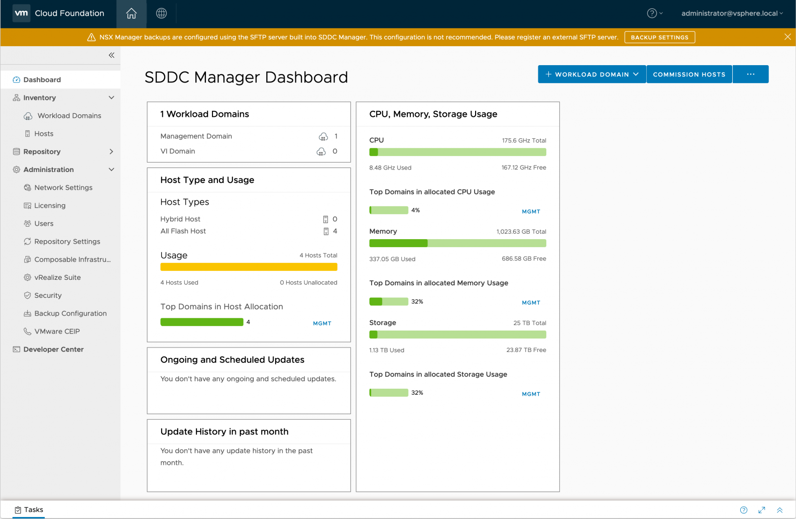
All VCF management activities are accomplished through SDDC Manager – no configuration changes should be made to any of the deployed components, including vCenter.
SDDC Manager: User Management
The ‘Users’ panel on the left of the interface shows a list of users inherited from the Platform Services Controller (PSC):

As such, identity sources from Active Directory, LDAP and OpenLDAP added to the PSC will appear here. Note that as there is only one role defined in SDDC Manager, namely ‘Cloud Admin’; all users will have the same level of access.
SDDC Manager: Privileged User
In order to perform password operations with SDDC manager, a privileged user account is required. Follow the steps below to create a new group in vCenter and associated new user.
First, in vCenter, create a new user that will be used for the privileged role:

Next, create the group ‘Sddc_Secured_access’ and add the newly created user:

SDDC Manager: Repository Settings
Once SDDC Manager is setup, users are required to enter their ‘My VMware’ account details to enable software bundle downloads. This may require configuration of a proxy in some environments.
Navigate to the ‘Repository Settings’ panel on the left of the interface and enter the account details:


Once bundles are available to download, the ‘Bundles’ panel will populate:

See the section on ‘LCM Management’ for further information on managing bundles.
SDDC Manager: Backup Configuration
It is recommended that the NSX managers are backed up to an external destination (currently SFTP is supported).
Navigate to ‘Backup Configuration’ on the panel on the left and click on ‘Register External’:

Enter the IP address, port, user credentials, etc. for the external destination:

SDDC Manager - Password Management
Service account passwords for deployed infrastructure components (e.g. ESXi hosts, NSX Manager) may be changed with SDDC Manager. SDDC Manager either updates passwords with a user-specified password (‘Update’ option), or automatically generates new randomly-generated passwords (‘Rotate’ option).
From the left panel, select Security > Password Management. Then, from the drop-down menu, select the component that will have passwords updated or rotated:

To rotate the password with a new, randomly generated password, select the user account(s) that need to be updated and click ‘Rotate’. This will bring up a window to enter the details of the privileged account information for SDDC Manager (to create a privileged user, refer to the 'SDDC Manager: Privileged User' section of this guide) :

To update a particular password with a new user-specified password, select only one user account, and click ‘Update’:

Note that the SDDC Manager password must be manually updated using the passwd command.
Passwords may be viewed by opening an SSH session to SDDC manager and issuing the following command:
/usr/bin/lookup_passwords
Workload Domain Overview
In VMware Cloud Foundation, a “workload domain” (or WLD) is a policy based resource container with specific availability and performance attributes that combines compute (vSphere), storage (vSAN, NFS, or VMFS on FibreChannel), and networking (NSX or NSX-T) into a single consumable entity. Each workload domain may be created, expanded, and deleted as part of the SDDC lifecycle operations, and may contain one or more clusters of physical hosts. Each workload domain is managed by a corresponding vCenter instance, which resides within the VCF management domain.
While the management domain always uses vSAN for storage, workload domains may use vSAN, NFS (version 3), or VMFS on FibreChannel (FC). The type of storage used by a workload domain is defined when each workload domain is initially created. After the workload domain has been created with a specific storage type, the storage type cannot be changed later. Additionally, the storage type selected during workload domain creation applies to all clusters that are created within the workload domain.
VCF 3.9.1 permits provisioning of three (3) workload domain types:
- Virtual Infrastructure (VI) Workload Domain – Basic workload domain suitable for any workload
- PKS Workload Domain – A specialized type of VI workload domain. Automates deployment of VMware Enterprise PKS components and infrastructure within the workload domain
- Horizon Workload Domain – A specialized type of VI workload domain. Automates the deployment of VMware Horizon components and infrastructure to deliver Virtual Desktop Infrastructure (VDI) and Remote Desktop Session Host (RDSH) capabilities within the workload domain
Each VCF workload domain requires a minimum of three (3) hosts. Exact requirements vary depending on the workload domain type the host resides in. See the table below for details.
|
Component |
Requirements |
|
Servers |
Servers within a cluster must be of the same model and type. |
|
CPU, Memory, and Storage |
|
|
NICs |
Note: Servers may have a maximum of two NICs for primary communication, plus one BMC NIC for out-of-band host management. |
In this proof of concept guide, we will focus on configuration of workload domains with vSAN-backed storage. For configuration of NFS or FC-backed storage, please consult the Cloud Foundation documentation in conjunction with documentation from the NFS or FC storage array vendor.
Create VI Workload Domain
To configure a new VI workload domain, a minimum of three unused vSphere hosts must be available in the Cloud Foundation inventory. Each host must meet the configuration and compatibility requirements specified above in Table A.
Further, the host management interfaces should be accessible by SDDC Manager, and appropriate upstream network configurations should be made to accommodate vSphere infrastructure traffic (i.e. vMotion, vSAN, NSX/NSX-T, management traffic, and any required VM traffic.
If available hosts that meet requirements are not already in the Cloud Foundation inventory, they must be added to the inventory via the Commission Hosts process. Hosts that are to be commissioned should not be associated with a vCenter instance and should not be a member of a cluster. Additionally, prior to commissioning, each host must meet certain configuration pre-requisites:
- Host for vSAN-backed workload domains must be vSAN compliant and certified per the VMware Hardware Compatibility Guide. BIOS, HBA, SSD, HDD, etc. must match the VMware Hardware Compatibility Guide.
- Host has a standard virtual switch back by two (2) physical NIC ports with a minimum 10 Gbps speed. NIC numbering should begin with vmnic0 and increase sequentially.
- Host has the drivers and firmware versions specified in the VMware Compatibility Guide.
- Host has ESXi installed on it. The host must be preinstalled with supported versions listed in the BOM.
- SSH and syslog are enabled on the host.
- Host is configured with DNS server for forward and reverse lookup and FQDN.
- Hostname should be same as the FQDN.
- Management IP is configured to first NIC port.
- Ensure that the host has a standard switch and the default uplinks with 10Gb speed are configured starting with traditional numbering (e.g., vmnic0) and increasing sequentially.
- Host hardware health status is healthy without any errors.
- All disk partitions on HDD / SSD are deleted.
- Ensure required network pool is created and available before host commissioning.
- Ensure hosts to be used for VSAN workload domain are associated with VSAN enabled network pool.
- Ensure hosts to be used for NFS workload domain are associated with NFS enabled network pool.
- Ensure hosts to be used for VMFS on FC workload domain are associated with NFS or VMOTION only enabled network pool.
To commission a host in SDDC manager, navigate to the Inventory > Hosts view, and select ‘Commission Hosts’ at the top right of the user interface.

Verify that all host configuration requirements have been met, then click ‘Proceed’.

On the next screen, add one or more hosts to be commissioned. These may be added via the GUI interface, or alternatively may be added through a bulk import process.
To add hosts via the GUI, ensure the ‘Add new’ radio button has been selected, and fill in the form. Then, click ‘Add’ at the lower right:

Alternatively, to bulk import hosts, click the ‘JSON’ hyperlink to download a JSON template for entering host information. After entering host details into the .JSON file, save it locally and select the ‘Import’ radio button. Then, click ‘Browse’ to select the .JSON file, and click ‘Upload’ at the lower right to upload the file to SDDC Manager:

When all hosts for commissioning are added, confirm the host fingerprints by selecting all hosts in the ‘Hosts Added’ table by clicking the grey circle with a check-mark located beside each host fingerprint listed in the ‘Confirm Fingerprint’ column. When the circle turns green, click the ‘Validate All’ button located near the upper right of the table:

After clicking ‘Validate All’, wait for the host validation process to complete. This may take some time. When the validation process completes, verify that all hosts have validated successfully, then click ‘Next’ to advance the wizard.

On the final screen of the wizard, review the details for each host, then click ‘Commission’ to complete the process:

The commissioning process will take some time. A status indicator will appear in the SDDC Manager interface:

Additionally, a ‘Commissioning’ task will appear in the Tasks list:

To create a VI workload domain, navigate to the Workload Domains inventory view. Then, at the top right of the screen, click “+Workload Domain”, then select VI – Virtual Infrastructure from the dropdown:

On the next screen, choose the storage type to use for this workload domain (this cannot be changed later). This guide will demonstrate vSAN storage configuration. After choosing, click ‘Begin’:

The VI Configuration wizard will now open. Begin by entering basic details about the workload domain. Then, click ‘Next’:

On the next screen, enter configuration details for vCenter. Note that information will be used to provision a new instance of vCenter. This instance’s VM resides in within the Management workload domain, and manages the clusters associated with its respective VI workload domain. Please ensure that valid forward and reverse DNS entries for the vCenter FQDN are configured, then click ‘Next’:

On the next screen, choose the version of NSX to deploy, and enter the deployment parameters. Ensure that forward and reverse DNS entries for NSX Manager FQDNs are be configured, and that the correct NSX software bundles have been downloaded on SDDC Manager. Then, click ‘Next’:

On the fourth screen in the wizard, configure the vSAN default Failures To Tolerate (FTT). Enabling the Dedupe and Compression feature for all-flash clusters is optional. Then, click ‘Next’:

The next step requires selecting available hosts from inventory to add to the workload domain. If there are no hosts available, please follow the instructions above for commissioning hosts within SDDC Manager.
VMware recommends deploying no less than 4 hosts per workload domain in order to ensure that compliance with vSAN FTT=1 policies may be maintained if a vSAN cluster host is offline. However, in cases where hosts available for the POC are limited, it is acceptable to construct a workload domain with the minimum three (3) required hosts, then later add an additional host for the purposes of demonstrating workload domain expansion functionality.
For clusters supporting vSAN FTT polices greater than one (1) (i.e. FTT=2 or FTT=3), it is recommended to deploy at least one additional host above the minimum required for policy compliance. See the vSAN Design and Sizing guide for additional details.
After selecting the hosts to be added, click ‘Next’:

Now, choose licenses available within SDDC Manager for the workload domain. If no applicable licenses are present, please add them to SDDC Manager (Administration > Licensing) then click ‘Next’:

On the next screen, review the object names associated with the workload domain deployment, then click ‘Next’:

Finally, review the deployment summary, then click ‘Finish’ to launch the deployment:

Wait while SDDC Manager deploys the VI workload domain.
Workload Domain Creation
Information on creation of a workload domain
Review Workload Domain Components
Components deployed during the workload domain creation process may be viewed within SDDC Manager. To view these components, navigate to Inventory > Workload Domains, then click ‘View Details’ in the summary for deployed Virtual Infrastructure (VI) Workload Domains:

From the list of VI Workload Domains, click the name of the domain that was deployed:

Within the ‘Services’ view, a list of deployed components is displayed. Clicking on the FQDN of a displayed component will navigate to the management interface for that component:

Review Workload Domain Summary
Clicking on the name of a workload domain within the inventory navigates to the summary view for that workload domain:

Other information within this view includes:
- Services: A list of services associated with the workload domain
- Updates/Patches: A summary of available updates and patches for systems and services associated with the workload domain
- Update History: The history of updates and patches applied to the workload domain
- Hosts: A list of hosts associated with the workload domain
- Clusters: A list of clusters associated with the workload domain
- Security: Certificate management for systems and service associated with the workload domain
Expand Workload Domain Cluster
To expand the host resources available within a workload domain, the SDDC Manager interface is used to move one or more unused hosts from the SDDC Manager inventory to a workload domain cluster.
Before attempting to add additional hosts to a workload domain, verify that ‘Unassigned’ hosts are available in the SDDC Manager Inventory:
If no hosts are presently ‘Unassigned’, please follow the host commissioning process to make one or more hosts available for use. Instructions for the commissioning process are included in section 4.1.1 of this document.
To add additional hosts to a workload domain, navigate to the target workload domain summary in the Workload Domains inventory, then access the ‘Clusters’ view. Then, click the name of the cluster that will be expanded to open the cluster summary view:
Navigate to Actions > ‘Add Host’
Select one or more vSphere hosts from inventory, then click ‘Next’:
Then, select a vSphere license to apply to the host(s) from the dropdown menu, then click ‘Next’:

Finally, review the host information, then click ‘Finish’:
SDDC Manager will now expand the target cluster by adding the selected host(s).
Create Horizon Workload Domain
Note: While creating at least one VI workload domain is necessary to demonstrate Cloud Foundation features, creation of a Horizon workload domain is optional.
Creating a Horizon workload domain involves many different dependencies specific to VMware Horizon, such as connection servers, load balancers, app volumes, UAG appliances, etc. Moreover, since a Horizon deployment usually connects to an Active Directory domain, there will need to be a routable network in place to facilitate this. Therefore, it is imperative that a high-level design be planned, especially in relation to the network routing.
The option to deploy a Horizon workload domain will be greyed-out until the appropriate Horizon bundles have been downloaded (see section 2.5 on how to setup the repository). Refer to the VCF Release Notes for the version of Horizon that should be downloaded.
Example Horizon bundle within the Repository view:

Verify that the appropriate licenses have been added – on the left panel, select ‘Licensing’. To add a license, click ‘+ License Key’:

Then select ‘VMware Horizon’ from the drop-down for Product Name and enter the license key:

In order to create a Horizon domain, the following must be created first (see the section on ‘Prerequisites for a Horizon Domain’ in VMware Cloud Foundation Operations and Administration guide for more information):
- At least one VI workload domain that will be consumed
- The Horizon management network (details of this may be found in the VMware Cloud Foundation Operations and Administration Guide, under the section ‘Working with Horizon Domains’)
- (Optional): The DMZ and interconnect networks
- The Horizon management VMs (connection servers, composers, UAG appliances, etc.)
- DNS records for all the above
- VXLAN port groups for the Horizon Management VMs
- Active Directory connection and records: usually two groups with admin privileges are required: one for the connection servers, and one for app volumes
- A customized Windows OVA
- A supported SQL server
Once the infrastructure is ready, navigate to Workload Domain > Horizon in SDDC Manager:

Then either select ‘Create a new Horizon Domain’ or, if a JSON configuration file has been created, ‘Upload Configuration’:

Next, a checklist appears as a reminder of the components required. When ready, click on ‘Start Configuration’
Then the configuration may begin, enter the required information for the Horizon domain name, VM prefix, Windows OVA details, etc.:

For more information on each section, see the ‘Create a Horizon Domain’ section in the VMware cloud Foundation Operations and Administration Guide.
After completing all details needed, SDDC Manager will run through some validation checks. Once these are complete, click ‘Next’ to start the deployment. To view verbose progress details while deployment is running, open an SSH session to SDDC Manager using the vcf account, and use tail to display the solution manager log:
tail –f /var/log/vmware/vcf/solutionmanager/solutionmanager.log
NSX Integration
A set of NSX overview walkthroughs
NSX Overview
NSX provides the core networking infrastructure in the software-defined data center stack within VCF. Every workload domain is integrated with and backed by an NSX platform. The Management workload domain is preconfigured with NSX-V. However, for VI workload domains, both NSX-V and NSX-T are supported. We will walk through the verification procedure below to review the NSX components installed in each workload domain.
NSX Configuration: Management Workload Domain
During the VCF bring-up process, NSX-V is automatically installed in the management workload domain. Its default components include an NSX Manager instance and three controller nodes. Follow the steps below to review whether these components are installed properly:
- Log into SDDC Manager
- In the left panel, navigate to Inventory > Workload Domains
- Select the workload domain that is of type ‘MANAGEMENT’ (‘MGMT’ in this example):

Select the management cluster, (‘mgmt01’ in this example):

Select Actions > Open in vSphere Client to open a vSphere Client UI in a new browser tab:

Navigate to Menu >Networking and Security in the vSphere Client UI:

If NSX is installed properly, the System Overview Dashboard should report green status for all components including the NSX Manager and three controller nodes:

NSX Configuration: VI Workload Domain(s)
When creating a VI workload domain, either NSX-V or NSX-T may be deployed to support its networking stack. In the last chapter, examples featured a workload domain with NSX-T based networking. Note that there are additional prerequisites for deploying NSX-T; please refer to the VCF Product Documentation for details.
A cluster of three NSX-T Manager nodes is deployed by default when the first NSX-T based workload domain is created. Follow these steps to review and verify its deployment:
In SDDC Manager, navigate to the VI Workload Domains page and select an NSX-T based workload domain:

On the workload domain page, select the Services view, and then the FQDN of the NSX-T Cluster. This will open a new browser tab and automatically log into one of the NSX-T Manager instance:

The landing page of the NSX-T GUI shows the system overview in the bottom right-hand corner. There should be three NSX Management nodes in the cluster. Select “NSX Management Nodes” to examine their status:

Confirm that the NSX-T management cluster is in ‘STABLE’ state. Also verify that the Cluster Connectivity for each node is ‘Up’:

Press the back button in the browser to return to the overview page and select “Transport Zones”. There are two types of transport traffic: Overlay and VLAN. There should be one transport zone created for each type of traffic as shown below:

Press the back button again in the browser to return to the NSX-T landing page and select “Host Transport Nodes”. On the “Host Transport Nodes” page, select the workload domain vCenter in the “Managed by” drop-down list to show all transport nodes in the cluster. Ensure the ‘Configuration’ is set to ‘Success’ and “Node Status” is ‘Up’ for each node:

Once the NSX Manager nodes, transport nodes, and base transport zones are in place, this concludes the initial deployment of NSX-T. However, additional configurations for NSX Edge nodes are required to allow North-South traffic in the data center. The deployment and configuration specifics of Edge nodes/cluster are beyond the scope of this document; detailed configuration procedures may be found in the VCF Product Documentation.
Stretching VCF Management and Workload Domains
A quick guide into stretching VCF Management and Workload Domains
Stretched Cluster Prerequisites
The process of stretching Cloud Foundation workload domains initiates a vSAN stretched cluster task. Rather than running this task within a managed vSAN cluster, this process is initiated by SDDC Manager, allowing SDDC Manager’s aware of this topology change. The same prerequisites that apply to vSAN stretched clusters also apply to Cloud Foundation stretched clusters.
Stretching Cloud Foundation workload domains allows for the extension of a domain across two availability zones (AZ) running on distinct physical infrastructure. Although there is no distance limitation, key requirements include:
- Latency below 5ms round trip time (RTT) between each availability zone
- At least 10Gbps of bandwidth between availability zones
Additionally, prior to stretching a cluster in a VI workload domain, the management domain cluster must be stretched first. vCenter Servers for all workload domains are hosted within the management domain. Hence, the management domain must be stretched to protect against availability zone failure, ensuring that supporting SDDC components may continue to manage the workload domain
Each stretched cluster requires a vSAN witness appliance in a third location. The witness should not share infrastructure dependencies with either availability zone; deployment of the witness to either availability zone it is associated with is not supported. The maximum latency between the vSAN witness appliance and the vSAN hosts is 200ms round trip time (RTT). This appliance is currently not part of SDDC Manager workflows; it should be deployed manually, and upgraded separately from SDDC LCM process. TCP and UDP ports must be permitted for witness traffic between the witness host and the vSAN cluster data nodes; see KB article 52959.
An in-depth list of requirements may be found on the “Deployment for Multiple Availability Zones” document; please review this document prior to any attempt to stretch Cloud Foundation workload domains.
Each AZ must have an equal number of hosts in order to ensure sufficient resources are available in case of an availability zone outage.
License Verification
Prior to stretching VCF workload domains, please verify that licenses are not expired and that the correct license type for each product is entered within SDDC Manager.
vSAN Licensing
Stretching a workload domain in VCF requires that vSAN Enterprise or Enterprise Plus licensing is present within SDDC Manager in order to stretch vSAN clusters. Refer to KB 70328 for information about a known licensing issue.

VLAN Configuration Requirements
The management VLAN, vSAN VLAN, and vMotion VLAN must be stretched between each availability zone. VLAN IDs must be identical at each availability zone.
Availability Zone Network Configurations
Each availability zone must have its own vSAN, vMotion and VXLAN VLAN networks.
Any VMs on an external network must be on an NSX virtual wire. If they are on a separate VLAN, that VLAN must be stretched as well.

L3 Routing for vSAN
vSAN Witness management and vSAN Witness traffic may utilize Layer 3 networks. Additional configuration may be required such as Witness Traffic Separation (WTS) and well as static routing. Please consult storagehub.vmware.com for further details.
Stretching Workload Domains
The Management workload domain must be stretched prior to stretching any VI workload domains. The vCenter servers for each workload domain are placed within the management domain cluster. Therefore, the management domain must be protected against availability zone failures to ensure management of the workload domains remains available.
After the Management workload domain has been successfully stretched, it is possible to apply stretched cluster configurations to other VI workload domains that are managed by the Cloud Foundation instance. The process of stretching VI workload domains is the same as the process that was previously used to stretch the Management workload domain.
Network Pool Creation
Prior to stretching the management domain, a network pool must be created for vMotion and storage networks.
The subnet in a network pool cannot overlap the subnet of another pool. IP ranges cannot be edited after the network pool has been created, so please ensure the correct IP address range is entered.
To create the network pool:
- From SDDC Manager Dashboard, click Administration > Network Settings
- Click ‘+ Create Network Pool’

- Enter a name for the network pool
- Select the storage network type
- Provide the following information for vMotion and the selected storage network type
- VLAN ID between 1-4094
- MTU between 1500-9216 N.B. Make sure any physical switch traffic overhead is accounted for
- In the Network field, enter a subnet IP address
- Enter the subnet mask
- Enter the default gateway
- Enter an IP address range for hosts to be associated with this network pool

Commission Hosts
Hosts are added to the Cloud Foundation inventory via the commissioning workflow. Hosts may be added individually or use a JSON template to add multiple hosts at once. Up to 32 hosts at a time may be commissioned. For additional details and requirements, refer to section 4.1.1 of this document.
In order to stretch the VCF management domain, hosts equivalent in number to those presently in the management domain cluster must be commissioned. These hosts will be used to construct the second availability zone (AZ2).
Associate Hosts to Network Pool
During the commissioning process, the network pool previously created for AZ2 must be associated with the hosts being provisioned for the stretched management domain cluster in AZ2.
Verify Host Health
Verify that all hosts commissioned are free of errors and are healthy prior to stretching the management domain.
Deploy vSAN Witness
Deploying the vSAN witness is a critical dependency supporting stretched management domains. The witness host may be a physical ESXi host, or the VMware-provided virtual witness appliance may be used (preferred). Please refer to vSAN witness information here for further details.
The vSAN witness host/appliance must be located in a third location outside of either availability zone it is associated with. Wherever the witness host/appliance is located, it should not share infrastructure dependencies with either availability zone. Due to its relatively relaxed latency requirement of 200ms RTT, the witness may even be hosted in the cloud. Witness traffic may utilize either Layer 2 or Layer 3 connectivity. Note that witness traffic is not encrypted, as it only contains non-sensitive metadata.
It is important to highlight that as of the VCF 3.9 release, witness deployment and lifecycle management are currently not part of any SDDC manager workflows. Therefore, the witness host/appliance must be deployed and upgraded independently from any SDDC Manager automation or management.
Please refer to detailed instructions for deployment of the witness appliance.
SDDC Manager Configuration
In order to stretch the management domain cluster, it is necessary to use the Support and Serviceability Tool (SoS):
- SSH into SDDC Manager VM using the vcf user account
- Enter su to switch to root user and navigate to the /opt/vmware/sddc-support directory
- Gather necessary information such as Domain Name, Cluster Name, HOSTFQDN(s), Witness Host FQDN, Witness IP CIDR, and ESXi license. Then enter the following command, replacing bracketed content as appropriate:
./sos --stretch-vsan --sc-domain <DOMAIN NAME> --sc-cluster <CLUSTER NAME> --sc-hosts <HOSTFQDN,HOSTDQND2,...> --witness-host-fqdn <WITNESS HOST FQDN> --witness-vsan-ip <WITNESS VSAN IP> --witness-vsan-cidr <WITNESS VSAN CIDR> --esxi-license-key <LICENSE KEY>
Example:
# ./sos --stretch-vsan --sc-domain MGMT --sc-cluster SDDC-Cluster1 --sc-hosts esxi-5.vrack.vsphere.local,esxi-6.vrack.vsphere.local --witness-host-fqdn esxi-11.vrack.vsphere.local --witness-vsan-ip 10.0.12.96 --witness-vsan-cidr 10.0.12.0/24 --esxi-license-key AAAAA-BBBBB-CCCCC-DDDDD-EEEEE

Welcome to Supportability and Serviceability(SoS) utility!

Logs : /var/log/vmware/vcf/sddc-support/stretchCluster-2019-02-13-08-51-34-12479
Stretch Cluster operation log : /var/log/vmware/vcf/sddc-support/stretchCluster-2019-02-13-08-51-34-12479/sos.log

Starting vSAN stretched cluster operations..

Api Response:{
"taskId": "d670ff00-24a3-4739-b5ff-b5317d709f36",
"resourceId": "0f8d112d-aa3f-4ca8-a8bd-b95e0e1ea2f5",
"resourceType": "ESXI",
"state": "IN_PROGRESS",
"description": "Stretch vSAN Cluster - SDDC-Cluster1 in VMware Cloud Foundation",  "timestamp": 1550047894872,
"id": "d670ff00-24a3-4739-b5ff-b5317d709f36"}
Check vSAN Health
While the cluster is being stretched, monitor the state of the task from the SDDC Manager Dashboard. When the task completes successfully, check the health of the vSAN cluster and validate that stretched cluster operations are working correctly by logging in to the vCenter UI associated with the workload domain.
To check the vSAN Health page:
- On the home page, click Host and Clusters and then select the stretched cluster
- Click Monitor > vSAN > Health
- Click Retest
- Troubleshoot any warnings or errors
Refresh vSAN Storage Policies and Check Compliance
It is imperative to check the vSAN storage policy compliance to ensure all objects achieve a state of compliance.
To check vSAN storage policies:
- On the vCenter home page, click Policies and Profiles > VM Storage Policies > vSANDefault Storage Policy
- Select the policy associated with the vCenter Server for the stretched cluster
- Click Monitor > VMs and Virtual Disks
- Click Refresh
- Click Trigger VM storage policy compliance check
- Check the Compliance Status column for each VM component
- Troubleshoot any warnings or errors
Lifecycle Management (LCM)
Learn more about Lifecycle Management related assets
Lifecycle Management Overview
The Lifecycle Management (LCM) feature of VMware Cloud Foundation enables automatic updating of both the Cloud Foundation software components (SDDC Manager, HMS, and LCM) as well as the VMware SDDC Components such as vCenter Server, PSC, ESXi, vSAN and NSX.
Lifecycle Management in SDDC Manager may be applied to the entire infrastructure or to a specific workload domain. The process is designed to be non-disruptive to tenant virtual machines. As new software updates become available, the SDDC Manager provides notifications to VCF Administrators, who may review the update details and, at a time convenient to them, download and schedule the updates.
This module demonstrates usage of the Cloud Foundation Lifecycle Management feature to upgrade from VMware Cloud Foundation 3.9 to VMware Cloud Foundation 3.91.
Bundle Types
Cloud Foundation utilizes two types of bundles for Lifecycle Management: Upgrade Bundles, and Install Bundles.
Upgrade Bundles
An upgrade bundle contains patches and other software necessary to update VCF software components. In most cases, an upgrade bundle must be applied to the management domain before it may be applied to workload domains.
Some upgrade bundles are cumulative bundles. In cases where a workload domain is multiple versions behind the target version, cumulative bundles allow Cloud Foundation to directly upgrade to the target version, rather than requiring the installation of multiple bundles in a sequential progression. Cumulative bundles are only available for vCenter Server, Platform Services Controller, and ESXi components.
Install Bundles
Install bundles contain software necessary to deploy new instances of Cloud Foundation components. For instance, VI workload domain install bundles are used to deploy more recent versions of the software components that were not present in the initial Cloud Foundation BOM; these install bundles include software for vCenter Server and NSX for vSphere.
Install bundles are also used to deploy optional components, such as vRealize Automation and vRealize Operations Manager, NSX-T, Horizon, and Enterprise PKS.
Downloading Bundles
If SDDC Manager is configured with My VMware credentials, Lifecycle Management automatically polls the VMware software depot to access software bundles. SDDC Manager will prompt administrators when a bundle is available and ready for download.
If SDDC Manager does not have Internet connectivity, software bundles may either be acquired via HTTP(S) proxy, or through a manual download and transfer process.
This guide demonstrates procedures for automatically downloading bundles, and manually downloading and transferring bundles. For the procedure to download bundles with a proxy server, please refer to the VMware Cloud Foundation Upgrade Guide.
Configure Credentials
On the left navigation pane navigate to Administration > Repository Settings. From the My VMware Account Authentication wizard, enter valid My VMware credentials.
Once My VMware credentials are validated the Repository settings will display as ‘Active’.
In some environments, it may be necessary to configure SDDC Manager to utilize a HTTP(S) proxy.
Download Bundles
After registering My VMware credentials, navigate to Repository > Bundles.
Locate and click ‘Schedule for Download’ or ‘Download Now’ to obtain the VMware Software Install Bundle - vRealize Suite Lifecycle Manager.

Repeat steps for VMware Software Install Bundle - vRealize Operations Manager.
Other bundles may be downloaded as well, but the above two are required for configuration steps that follow.
Deploy vRealize Lifecycle Manager
After bundles have been downloaded successfully, Navigate to Administration > vRealize Suite.
Select ‘Deploy’ from the landing page. The install wizard will launch with vRealize Suite Lifecycle Manager Installation Prerequisites.
Select the ‘Select All’ option, then and click ‘Begin’.
Enter in VLAN, Subnet and Gateway specific to the environment.
DNS and NTP should already be set. Click ‘Next’:

Add FQDN of the appliance, the system password and root appliance password:

Click ‘Next’
Review and finish to deploy appliance.
Monitor Deployment Progress
vRealize Suite Deployment may be monitored from the Dashboard and Tasks views in SDDC Manager:

Please wait for deployment to complete before proceeding.
Validate Deployment
Once vRealize Lifecycle Manager has been successfully deployed, connect to vRealize Lifecycle Manager by following the blue hyperlink.

Login using the System Admin login - admin@localhost:

Verify the vRealize Log Insight deployment for the Management Cluster has been discovered by selecting ‘Manage Environments’
Select ‘VIEW DETAILS’ on vRLI_environment dashboard

Installing Upgrade Bundles
Completing an upgrade of all the components of an SDDC without Cloud Foundation requires careful planning and execution. Cloud Foundation’s ability to orchestrate a non-disruptive upgrade of SDDC components is a key benefit of the Cloud Foundation platform.
When new updates or software packages are available, a notification will appear in the SDDC Manager interface:

Clicking on the ‘View Updates’ navigates to the Lifecycle Management interface. The Lifecycle Management interface will display available bundles.
SDDC Manager will automatically complete all the tasks required to install this update. When the first update in this series of updates are completed successfully, the other updates may be completed using the same steps until components are updated to the latest version.
vRealize Automation (vRA) Integration
A guide into the vRA assets
Overview
vRealize Automation is a component of of VMware’s vRealize Suite. vRealize Automation (vRA) allows reduced complexity of IT operations, streamlines IT processes, and delivers a DevOps-ready automation platform. Additional information regarding vRealize Automation use cases and functionality may be found on VMware.com.
vRealize Automation Prerequisites
Configure/Confirm Active Directory Account
If not created already, create an Active Directory (AD) account that will be used to add computer accounts and join Windows VMs to the domain. This account is also used to install and run the management agents and iaaS components for the vRealize Automation infrastructure, including proxy agents.
Verify Certificate and Private Key
Verify the certificate and private key. A multi-SAN certificate and private key generated by a trusted certificate authority must be utilized. When generating these certificates, specify the FQDN values of all vRealize Automation VMs and load balancer servers.
Verify IP Allocation and DNS Records
Verify that IP allocation and forward/reverse DNS records are prepared for the following components:
- All vRealize Automation virtual appliances and vRealize Automation IaaS virtual machines
- The vRealize Suite Lifecycle Manager virtual appliance (This is required only if not previously configured as part of deploying vRealize Operations in Cloud Foundation)
- All vRealize Suite load balancer VMs (This is required only if not previously configured as part of deploying vRealize Operations in Cloud Foundation)
Verify Microsoft SQL Configuration
Verify that Microsoft SQL Server is configured properly:
- Join the Microsoft SQL Server VM to Active Directory, create a new login for the administrative user in SQL Server, modify the firewall and port configuration, and create the SQL Database
- SQL server configuration specifics may be found here: Configuring Microsoft SQL Server for vRealize Automation in Cloud Foundation
Verify IaaS Windows Template
Create a Windows Server 2012 R2 or Windows Server 2016 virtual machine template (OVA). Details to prepare this template may be found here: Prepare the vRealize Automation Windows VM OVA Template.
Verify License Key for vRealize Automation
Ensure that licenses are present in SDDC Manager. Licenses for vRealize Automation are sold separately from Cloud Foundation.
Verify vRealize Network VLAN Configuration
The vRealize VLAN must be configured on TOR switches, and the vRealize subnet must be routable to the VCF Management network. The firewall between the Management and vRealize networks should be disabled or configured per the Cloud Foundation documentation.
Note: Microsoft SQL Server should be deployed in the vRealize Network in order to enable replication. If not deployed on the vRealize network, the replication should be performed by the user. If Microsoft SQL Server is not in the vRealize Network, make appropriate network changes to ensure vRealize Suite VMs to access it.
Deploy vRealize Automation
Prior to deploying vRealize Automation, vRealize Lifecycle Manager must be deployed and functioning. Configuration instructions for vRealize Lifecycle Manager are available in this guide. Additionally, a vRealize Automation software installation bundle must be downloaded.
Initiate deployment by navigating to Administration > vRealize Suite > vRealize Automation, then click “Deploy” :

Verify that all prerequisites are configured properly, then check the “Select All” box and click “Begin”:

On the Deployment Details page, enter the License Key, Certificate Details, and IaaS Windows Template. Click “Next” to continue.
On the FQDNs page, enter the fully qualified name of the vRealize Appliances, Iaas Web Servers, IaaS Manager Service and DEM Orchestrators, DEM Workers, Proxy Agents, vRealize Suite Lifecycle Manager, Load Balancers, and Microsoft SQL Server. All Settings are required. When complete, click “Next”.
IMPORTANT: The installation derives the Active Directory domain name for the computer account from the DNS suffix provided in the FQDN for each vRealize Automation IaaS component. For example, an FQDN of vra01.rainpole.local derives the Active Directory domain rainpole.local. If the DNS suffix is different from Active Directory domain name, the installation will be unsuccessful. For more information, see Knowledge Base article 59128.
On the Account Information page, input settings for Active Directory, Microsoft SQL Servers, Local Tenant Administrator, Windows Template Local Administrator, Default Tenant Administrator, and vRealize Automation SSH Root accounts. All settings are required. When complete, click “Next”.
On the Review Summary page, verify the information and then click “Finish”. The status will display “Deployment in progress”. If the deployment fails, the page will indicate that the deployment failed. In the event of a failure, choose either “Retry” or “Uninstall”.
IMPORTANT: The uninstall operation does not remove the computer accounts from Active Directory. As a result, this could cause a reinstallation to fail. Manually remove the computer accounts from Active Directory and recreate the Microsoft SQL Server database for vRealize Automation. See the VMware Cloud Foundation Planning and Preparation Guide.
After a successful deployment of vRealize Automation, the vRealize Automation page in SDDC Manager > Administration>vRealize Suite displays an ACTIVE status and displays controls that enable connecting vRealize Automation to workload domains.
vRealize Operations Manager (vROps) and vRealize Log Insight Integration
Learn more about the assets related to vRealize Operations Manager (vROps) and vRealize Log Insight Integration
Deploy vRealize Operations Manager (vROps)
Note: vRealize Suite Lifecycle Manager must be deployed prior to deploying vRealize Operations Manager.
Add a vRealize Operations Manager License
To add a vROps license, login to SDDC Manager and Navigate to Administration > Licenses.
Select “+ LICENSE KEY” to launch add new license key wizard.
From the ‘Product Name’ drop down list, select VMware vRealize Operations, add a valid ‘License Key’ and ‘Description’, then click ‘ADD’.

Deploy vRealize Operations Manager
To deploy vROps, navigate to Administration > vRealize Suite > vRealize Operations. Click ‘DEPLOY’, and the deploy wizard will launch:

Select All from vRealize Operations Installation Prerequisites, then click ‘BEGIN’.
Select HA Mode, as IP records for the Master, Replica and Data nodes are already allocated.
Sizing will depend on how many workload domains that will be deployed, and how large each workload domain will be. Use the official sizing tool to assist with sizing decisions.
For this example, select HA Mode, Medium and 3 nodes:

Enter in the fully qualified domain names for:
- NSX Edge Service Gateway: This is the IP and DNS record for vRealize Edge load balancer (shared component with vRealize Automation)
- vRealize Operations: This is the Virtual IP address for the load balancer for the analytics cluster of vRealize Operations Manager
- Node 1: This is the IP and DNS record Master node IP for vRealize Operations Manager master
- Node 2: An IP and DNS record Master replica node IP for vRealize Operations Manager
- Node 3: IP and DNS record Data node for vRealize Operations Manager

Click Next and enter the password for vRealize Operations System Administrator. Review and Finish. The wizard will validate inputs.
At this point vRealize Operations Manager should deploy successfully.

Validate vRealize Operations Deployment
To verify if vRealize Operations Manager is deployed correctly, connect directly to the vRealize Operations Cluster via web browser, utilizing the cluster FQDN or the Virtual IP address. Verify that the build in admin account authenticates, and verify the cluster status after logging in.
Validate that each vRealize Operations Manager appliances is accessible by authenticating to each with the built-in admin account.
To verify that the vRealize Operations Manager cluster is online, and that all appliances in the cluster are running:
- On the main navigation bar, click Administration.
- In the left pane, expand Management and click Cluster Management.
- Verify the Cluster Status and High Availability states:

To verify the cluster configuration, ensure all adapters are receiving data from the Management Cluster:
Adapter Status should be Data Receiving.
From the main menu, Select Administration > Configuration
The deployed Adapters are:
- VMware vSphere
- VMware vSAN
- VMware vRealize Log Insight

Select vCenter Adapter > Configure
Verify Connection by clicking TEST CONNECTION

If everything is configured correctly, this will complete successfully.
Repeat the TEST CONNECTION procedure for the vSAN and vRealize Log Insight Adapters.
To verify Dashboards Are populated with data from the management cluster:
Confirm that the two main adapters (vSphere and vSAN) are populating dashboards for MGMT cluster
Verify vSphere by navigating to Dashboards > vSphere Compute Inventory

Verify vSAN by navigating to Dashboards > vSAN Operations Overview

To verify the load balancer configuration:
- Connect to the vCenter management address. Select the management vCenter, then from drop down menu select Networking and Security. From the Networking and Security view, Select NSX Edges, click on edge-1
- From the status page, verify there are no errors and all services are functional:

Select and verify that the vRLI log Insight syslog server is configured for the NSX-V Edges:
Select Interfaces from the Configure pane, and verify that the deployed interfaces match the deployment names and IP addresses:
Finally, select Load Balancer from the Global Configuration pane and select Virtual Servers, and Pools. Confirm http and https redirects are configured on Virtual Severs.
Select Members and confirm 3 members are configured:

vRealize Log Insight Configuration
vRealize Log Insight was deployed during the initial Cloud Foundation bring-up.
Following deployment, vRealize Log Insight functionality may verified on SDDC Manager by navigating to Administration > vRealize Suite > vRealize Suite Lifecycle Manager > vRealize Log Insight:

Here, vRealize Log Insight may be configured to monitor additional workload domains that might be deployed.
Note: While ENABLE suggests that collection has not been configured, vRealize Log Insight is already collecting data from the Management Cluster hosts and NSX-V controllers.
The Enable button is used to enable log collection for new workload domains.
To verify Authentication in vRealize Log Insight by Using Local System Account and Verify the Cluster Status: In a Web browser, log in to vRealize Log Insight using the local admin credentials:
|
Setting |
Value |
|
URL |
https://vrli-vip-address |
|
Username |
admin |
|
Password |
<vrli_admin_password> |
To verify the status of the vRealize Log Insight cluster nodes:
- Click the configuration drop-down menu icon, then select Administration
- In the left pane, in the Management section, click Cluster
- Verify that the status of each cluster node is Connected and the status of the Integrated Load Balancer is Available

To verify the status of the vSphere and vRealize Operations Manager integration:
vSphere
- Click the configuration drop-down menu icon, then select Administration.
- In the left pane, in the Integration section, click vSphere.
- Verify the MGMT vCenter Instance is set to Collect Events, and the ESXi hosts are configured by clicking “more details”:

vRealize Operations
- Click the configuration drop-down menu icon, then select Administration.
- In the left pane, in the Integration section, click vRealize Operations
- Verify the hostname of vRealize Operations, username and password are correct by clicking Test:

Optionally:-
‘Enable launch in context’ may be enabled, allowing vRealize Operations Manager to open Log Insight and query for selected object logs. This also provides the ability for Log Insight to navigate to the vRealize Operations Manager object that generated the event.
Enabling this option may take a few minutes to register:

To verify Launch in context is working, login to vRealize Operations:
- Navigate to Enviroment > vSphere Environment > vSphere Hosts and Clusters > vSphere World > vSphere Adapter instance for the Management Cluster
- Navigate to Management Cluster and Logs
- Login to the vRealize Log Insight instance when prompted:

Once authenticated, it should be possible to navigate through the various dashboards to verify integration:

vRealize Log Insight Management and Content Pack Configuration
To examine vRealize Log Insight Content pack configuration, login to vRealize Log Insight with admin credentials.
Select the Administration section on top right of VRLI console, then navigate to content packs.
By default there should be 6 content packs:
- General
- Linux
- VMware-NSX-vSphere
- VMware – vSAN
- VMware – vROps 6.7+
- VMware - vSphere
Existing content packs may be updated by navigating to Updates:

To update all content packs, click UPDATE ALL. Once updates have completed, the release notes may be reviewed by inspecting each content pack.
At time of writing the following versions are current:
- Linux Version: 2.1
- VMware - NSX-vSphere Version: 4.0
- VMware - vROps 6.7+ Version: 3.1
- VMware - vSAN Version: 2.2
- VMware - vSphere Version: 8.0
Installing the NSX-T Content Pack
Optionally, if deploying NSX-T on additional workload domains, the NSX-T Content pack may be deployed from the marketplace.
The NSX-T content pack version 3.8.2 is compatible with Log Insight 4.8.
To deploy this content pack, navigate to Marketplace , then locate the VMware – NSX-T content pack. To install, agree to the terms and click INSTALL.

This permits configuration of logging for the NSX-T Manager, controllers, edges and hosts. For more information see NSX-T Administration guide on guidance for remote logging.
Verify Dashboards
Verify data is collected on the main dashboards for:
- VMware-NSX-vSphere
- VMware – vSAN
- VMware – vROps 6.7+
- VMware – vSphere.
For example for VMware NSX-vSphere, navigate to Dashboards , then select NSX-vSphere Overview:

Depending on the activity of the Management Cluster, it may be necessary to adjust time ranges to reveal data.
Repeat this process for VMware – vSAN, VMware – vROps 6.7+ and VMware – vSphere:
vROps:

vSAN:

vSphere:

Host Collection Status
To verify that configured hosts are sending data to Log Insight, navigate to Administration > Hosts . Verify data is being sent via the Last Received Event details.
For instance, in the example below, events from the configured hosts were received within the last 5 minutes:

Confirm the list of configured hosts match the deployed management and workload domains.
Connect vRLI and vROps to VI Workload Domains
vRealize Log Insight (vRLI)
On the SDDC Manager Dashboard, navigate to Administration > vRealize Suite.
To connect the vRealize Log Insight deployment to workload domains:
- Select vRealize Log Insight
- Under Enable Log Collection for All Workload Domains, click Enable:

A task will be initiated to connect to the workload domains:
To verify the VI workload domain has connected successfully, login to vRealize Log Insight, then navigate to Administration > vSphere.
There should be multiple vCenter systems registered: one for the Management workload domain, and one or more for other VI workload domains:


Verify that data is being collected.
vRealize Operations (vROps)
On the SDDC Manager Dashboard, navigate to Administration > vRealize Suite.
To connect the vRealize Operations deployment to new workload domains:
- Select vRealize Operations.
- Under Connect Workload Domains, select Connect/Disconnect Workload Domains.
- Select the workload domain(s) and click finish:

Monitor the task on the SDDC Manager task list:

To verify progress and see the configuration status of each vROps adapter, expand the subtasks for the task:

Once the task to connect to a workload domain completes, the vROps adapters may be inspected that they are collecting data:
- Connect to vROps, Navigate to Administration > Configuration > Solutions
- Verify the Workload domain vCenter is configured and collecting data:

Refer to section 7.3.4 for vROps validation for workload domains
Composable Infrastructure (Redfish API) Integration
Details on Infrastructure related assets
Overview
Beginning with version 3.8, Cloud Foundation supports integration with software-defined Composable Infrastructure, allowing for dynamic composition and decomposition of physical system resources via SDDC Manager. This integration currently supports HPE Synergy and Dell MX Composable Infrastructure solutions. This integration leverages each platform’s Redfish API.
HPE Synergy Integration
To enable infrastructure composability features, deploy the HPE OneView Connector server.
Procedure:
- Deploy Linux server (physical or VM)
- Install HPE OneView connector for VCF on the Linux server
- Complete bring-up SDDC Manager if not already done
- Increase queue capacity for the thread pool
- Connect to SDDC Manager via SSH using the vcf account
- Escalate to root privileges with su
- Open the file application-prod.properties:
vi /opt/vmware/vcf/operationsmanager/config/application-prod.properties
- Update the queue capacity line:
om.executor.queuecapacity=300
- Save and close the file
- If using a self-signed certificate, import the Redfish certificate from the OneView Connector server:
- SSH in to SDDC Manager using the vcf account
- Enter su to escalate to root
- Import certificate from Redfishto SDDC Manager:
/opt/vmware/vcf/commonsvcs/scripts/cert-fetch-import-refresh.sh --ip=<redfish-ip> --port=<SSL/TLS port> --service-restart=operationsmanager
- Restart the SDDC Operations Manager service:
systemctl restart operationsmanager
Wait a few minutes for the service to restart, then connect Cloud Foundation to the composability translation layer:

Dell MX Integration
Dell MX Composable Infrastructure does not require a separate server instance to be deployed, as the Redfish API translation layer is integrated into the MX management module.
Certificates
A signed certificate is necessary in order to establish a connection with the OME Modular interface. The FQDN should be added to DNS as this is included in the certificate. Note that the certificate presented by the MX platform must have a CN that matches the FQDN of the MX management module; VCF will not connect if the default self-signed certificate (CN=localhost) is used.
The certificate CSR can be generated from the OME Modular Interface on the MX7000.
- Log in to the OME interface
- Select Application Settings from the main menu
- Security -> Certificates
- Generate a Certificate Signing Request
- Then upload the certificate when it is available
Configure Translation Layer
The translation layer must be configured prior to connecting the SDDC Manager to the composable infrastructure platform.
Procedure:
- Increase queue capacity for the thread pool
- Connect to SDDC Manager via SSH using the vcf account
- Escalate to root privileges with su
- Open the file application-prod.properties:
vi /opt/vmware/vcf/operationsmanager/config/application-prod.properties
- Update the queue capacity line:
om.executor.queuecapacity=300
- Save and close the file
- If using a self-signed certificate, import the Redfish certificate from the MX MSM to SDDC Manager.
- SSH in to SDDC Manager using the vcf account
- Enter su to escalate to root
- Import certificate from Redfishto SDDC Manager:
/opt/vmware/vcf/commonsvcs/scripts/cert-fetch-import-refresh.sh --ip=<MSM-ip> --port=<SSL/TLS port> --service-restart=operationsmanager
- Restart the SDDC Operations Manager service:
systemctl restart operationsmanager
- Wait a few minutes for the service to restart
- From SDDC Manager, click Administration > Composable Infrastructure
- Enter the URL for the Redfish translation layer

- Enter username and password for Redfish translation layer

- Click Connect
Composable resources will now be visible within the VCF UI.
