
VCF 4.1 Proof Of Concept Guide
POC Guide Overview
The purpose of this document is to act as a simple guide for proof of concepts involving VMware Cloud Foundation 4.1 and associated infrastructure tasks to configure and manage Software Defined infrastructure.
This document is intended for data center cloud administrators who deploy a VMware Cloud Foundation system in their organization's data center. The information in this guide is written for experienced data center cloud administrators.
This document is not a replacement for VMware product documentation however it should be thought of as a guide to augment existing guidance throughout the lifecycle of a proof-of-concept exercise.
Offical product documentation (https://docs.vmware.com/allproducts.html ) should supersede guidance documented here, if there is a divergence.
When referring to any statements made in this document, verification regarding support capabilities, minimums and maximums should be cross-checked against official VMware Technical product documentation at https://docs.vmware.com/en/VMware-Cloud-Foundation/index.html and https://configmax.vmware.com/ in case of more recent updates or amendments to what is stated here.
This document is laid out into several distinct sections to make the guide more consumable depending on the use case and proof of concept scenario as the guide aims to offer a structured approach during evaluation of VCF features.
VCF 4.1 What’s New / Overview
VCF 4.1 BOM updates and new features
Section 1 Planning / Day 0
This section covers guidance and requirements for VCF bring up and considerations such as external datacenter resources and dependencies.
Section 2 VCF Infrastructure Deployment / Day 1
Deployment of VCF infrastructure components such as Management, Workload domains and NSX-T Edge Clusters.
Section 3 vRealize Suite Install
Guidelines to deploy SDDC components as vRealize Operations and vRealize Log Insight.
Section 4 Solution Deployment guidelines.
Proof of Concept guidelines to deploy SDDC infrastructure using specific features and vSphere with Tanzu, Stretch Cluster, vVOLs or vLCM.
Section 5: Day 2 Use cases
NSX-T Network validation.
Certificate Management.
Password Management
VCF Upgrades
vRealize Suite Monitoring and Alerting configuration and management
Appendices
NSX-T overview
VCF 4.1 What’s New / Overview
Cloud Foundation Bill of Materials (BOM)
For more information, please refer to the release notes in case of updates or amendments
Below table lists the full BOM of VCF 4.1.
|
Software Component |
Version |
Date |
Build Number |
|
Cloud Builder VM |
4.1.0.0 |
06 OCT 2020 |
16961769 |
|
SDDC Manager |
4.1.0.0 |
06 OCT 2020 |
16961769 |
|
VMware vCenter Server Appliance |
7.0 Update 1 |
06 OCT 2020 |
16860138 |
|
VMware ESXi |
7.0 Update 1 |
06 OCT 2020 |
16850804 |
|
VMware vSAN |
7.0 Update 1 |
06 OCT 2020 |
16850804 |
|
VMware NSX-T Data Center |
3.0.2 |
17 SEP 2020 |
16887200 |
|
VMware vRealize Suite Lifecycle Manager |
8.1 Patch 1 |
25 AUG 2020 |
16776528 |
|
Workspace ONE Access |
3.3.2 |
14 APR 2020 |
15951611 |
|
vRealize Automation |
8.1 Patch 2 |
28 JUL 2020 |
16633378 |
|
vRealize Log Insight |
8.1.1 |
28 MAY 2020 |
16281169 |
|
vRealize Log Insight Content Pack for NSX-T |
3.9.0 |
n/a |
n/a |
|
vRealize Log Insight Content Pack for Linux |
2.1 |
n/a |
n/a |
|
vRealize Log Insight Content Pack for Linux - Systemd |
1.0 |
n/a |
n/a |
|
vRealize Log Insight Content Pack for vRealize Suite Lifecycle Manager 8.0.1+ |
1.0 |
n/a |
n/a |
|
vRealize Log Insight Content Pack for VMware Identity Manager |
2.0 |
n/a |
n/a |
|
vRealize Operations Manager |
8.1.1 |
09 JUL 2020 |
16522874 |
|
vRealize Operations Management Pack for VMware Identity Manager |
1.1 |
n/a |
n/a |
VCF 4.1 Summary update
For more information, please review
Release Notes
VCF 4.1 Blog
https://blogs.vmware.com/cloud-foundation/2020/09/15/whats-new-with-vmware-cloud-foundation-4-1/
- VCF Remote Clusters. Extending VCF capabilities to the ROBO & Edge sites with VCF Remote Clusters was added in this release
- ESXi Cluster-Level and Parallel Upgrades: Enables administrators to update vSphere software on multiple clusters in the management domain or a workload domain in parallel.
- NSX-T Data Centre Cluster-Level and Parallel Upgrades: Enables administrators to upgrade all Edge clusters in parallel, and then all host clusters in parallel
- Support for ESXi hosts with external CA signed certs: VCF supports APIs to perform bring-up of hosts with certificates generated by an external CA.
- Read-only access and local accounts: cloud admins can now create “Viewer” users that have read-only access to VCF. They can also create a local account for use in break-glass scenarios where a remote identity provider is unreachable
- Backup Enhancements:
SDDC Manager backup-recovery workflows and APIs have been improved to add capabilities such as backup management, backup scheduling, retention policy, on-demand backup & auto retries on failure - vVOLs as Principal Storage in VCF Workload Domain: VMware Cloud Foundation now supports vVOLs providing a common storage management framework for external storage, providing automation for pre-defined storage including volume management and provisioning.
- VMware Skyline Support for VMware Cloud Foundation: VMware Skyline brings proactive intelligence to VMware Cloud Foundation by identifying management and workload domains, and proactively surfacing VMware Cloud Foundation solution findings
- Object Rename Support. We now allow customers to change object names after initial deployment.
- vCLS Support – The vSphere Clustering Service (vCLS) is a new capability that is introduced in the vSphere 7 Update 1 release and is included in the VCF 4.1 release.
- Increase pNIC support –VI Workload domains can have hosts with multiple pNICs and vSphere Distributed Switches (vDS) that can scale up-to the vSphere maximums supported in the vSphere version included in the BOM.
Section 1 VCF Deployment Planning & Bring Up / Day 0
To plan for a successful VCF POC, there is a considerable number of external requirements to ensure success
The key to a successful plan is to use a reasonable hardware configuration that resembles what you plan to use in production.
Physical Network and External services
Certain requirements such as routable VLANS, MTU and DNS and DHCP services are required, these are in summary:
- Top of Rack switches are configured. Each host and NIC in the management domain must have the same network configuration.
- IP ranges, subnet mask, and a reliable L3 (default) gateway for each VLAN.
- Note its not strictly required to have a L3 gatway for vSAN, however Cloud Builder validation will post a warning that validation of L3 gateway failed.
- At minimum, an MTU of 1600 is required on the NSX-T Host Overlay (Host TEP) and NSX-T Edge Overlay (Edge TEP) VLANs end-to-end through your environment.
- VLANs for management, vMotion, vSAN, NSX-T Host Overlay (Host TEP), NSX-T Edge Overlay (Edge TEP), and NSX uplink networks are created and tagged to all host ports. Each VLAN is 802.1q tagged. NSX-T Host Overlay (Host TEP) VLAN and NSX-T Edge Overlay (Host TEP) VLAN are routed to each other.
- Management IP is VLAN-backed and configured on the hosts. vMotion and vSAN IP ranges are configured during the bring-up process.
- DHCP with an appropriate scope size (one IP per physical NIC per host) is configured for the NSX Host Overlay (Host TEP) VLAN.
AVNs or Application Virtual Networks are optional to configure but highly recommended to evaluate vRealize Suite and vSphere Tanzu
To use Application Virtual Networks (AVNs) for vRealize Suite components you also need:
- Top of Rack (ToR) switches configured with the Border Gateway Protocol (BGP), including Autonomous System (AS) numbers and BGP neighbor passwords, and interfaces to connect with NSX-T Edge nodes.
- Two VLANs configured and presented to all ESXi hosts to support the uplink configuration between the (ToR) switches and NSX-T Edge nodes for outbound communication.
Physical Hardware and ESXi Hosts
Refer to the VMware vSAN Design and Sizing Guide for information on design configurations and considerations when deploying vSAN. Be sure the hardware you plan to use is listed on the VMware Compatibility Guide (VCG). BIOS updates, and firmware and device driver versions should be checked to make sure these aspects are updated according to the VCG.
- Identical hardware (CPU, Memory, NICs, SSD/HDD, and so on) within the management cluster is highly recommended. Refer to vSAN documentation for minimum configuration.
- Hardware and firmware (including HBA and BIOS) is configured for vSAN.
- Physical hardware health status is "healthy" without any errors.
- ESXi is freshly installed on each host.
- Each ESXi host is running a non-expired license. The bring-up process will configure the permanent license.
Software and Licenses
- The ESXi version matches the build listed in the Cloud Foundation Bill of Materials (BOM). See the VMware Cloud Foundation Release Notes for the BOM.
- VCF Cloud Builder OVA
- Adequate licenses for VCF components and number of workload domains that is planned for deployment
Further online resources
- VMware Cloud Foundation Deployment guide - https://docs.vmware.com/en/VMware-Cloud-Foundation/4.1/com.vmware.vcf.ovdeploy.doc_41/GUID-F2DCF1B2-4EF6-444E-80BA-8F529A6D0725.html
- Planning and Preparation Workbook https://docs.vmware.com/en/VMware-Validated-Design/6.1/vmware-validated-design-61-vmware-cloud-foundation-41-sddc-planning-and-preparation-workbook.zip
This workbook supports both VMware Cloud Foundation 4.1 and VMware Validated Design 6.1. It is a Microsoft Excel workbook that helps you gather the inputs required for deploying Cloud Foundation (known as bring-up), VI workload domains, Workload Management, and vRealize Suite Lifecycle Manager. It also provides guidance on the requirements for additional components that you can add to your Cloud Foundation environment, such as vRealize Log Insight, vRealize Operations Manager, vRealize Automation, and VMware Workspace ONE Access. - Cloud foundation Tech Zone collateral and interactive demos https://core.vmware.com/
- Parameter worksheet and bring up process https://core.vmware.com/deploying-cloud-foundation
- Deploying vRealize Suite on VMware Cloud Foundation https://core.vmware.com/deploying-vrealize-suite-vmware-cloud-foundation
Step by step overview on how to stand up Enabling Kubernetes on Cloud Foundation on VMware Cloud Foundation
https://core.vmware.com/delivering-developer-ready-infrastructure#step_by_step_guide_to_deploying_developer_ready_infrastructure_on_cloud_foundation_isim_based_demos
Management Workload Domain Overview
SDDC Manager and other vSphere, vSAN, and NSX components that form the core of VMware Cloud Foundation are initially deployed to an environment known as the Management workload domain. This is a special-purpose grouping of systems devoted to managing the VMware Cloud Foundation infrastructure.
Each Cloud Foundation deployment begins by establishing the Management workload domain, which initially contains the following components:
- SDDC Manager
- vCenter Server with integrated Platform Services Controller
- vSAN
- NSX-T

Management Workload Domain Logical View:
In addition to the Cloud Foundation components that are provisioned during the bring-up process, additional virtual machine workloads may be deployed to the Management workload domain if required. These optional workloads may include third party virtual appliances or other virtual machine infrastructure workloads necessary to support a particular Cloud Foundation instance.
The vCenter with internal Platform Service Controller instance deployed to the Management workload domain is responsible for SSO authentication services for all other workload domains and vSphere clusters that are subsequently deployed after the initial Cloud Foundation bring-up is completed.
Additional details regarding the configuration and usage of Cloud Foundation workload domains may be found in the following section of this guide, Workload Domain Creation.
Prerequisites and Preparation
VMware Cloud Foundation (VCF) deployment is orchestrated by the Cloud builder appliance, which builds and configures VCF components. To deploy VCF, a parameter file (in the form of an Excel workbook or JSON file) is used to set deployment parameters such as host name, IP address, and initial passwords. Detailed descriptions of
VCF components may be found in the VCF Architecture and Deployment Guide.
The Cloud Builder appliance should be deployed on either an existing vSphere cluster, standalone host, or laptop (requires VMware Workstation or VMware Fusion). The Cloud Builder appliance should have network access to the Management Network segment defined the parameter file to enable connectivity to the ESXi hosts composing the management workload domain.
There are specific requirements that need to be fulfilled before the automated build process or ‘bring-up’ may begin. for instance, DNS records of the hosts, vCenter, NSX Manager, etc. should have been configured. Before starting, download the parameter spreadsheet to support planning and configuration of deployment prerequisites.
The OVA for Cloud Builder appliance and parameter workbook (Cloud Builder Deployment Parameter Guide) for version 4.1 can be found at:
https://my.vmware.com/web/vmware/downloads/info/slug/datacenter_cloud_infrastructure/vmware_cloud_foundation/4_1_0
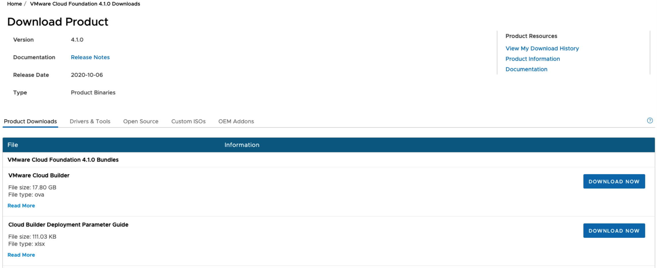
Alternatively, the parameter workbook may also be downloaded from the Cloud Builder appliance after it has been deployed.
Once the workbook has been completed, the file should be uploaded to the appliance, where upon a script converts the Excel to a JSON file. This JSON file is then validated and used in the bring-up process.
The VMware Cloud Foundation YouTube channel is a useful resource to reference alongside this guide.
Deploy Cloud Builder Appliance
Download the Cloud Builder appliance and import the OVA. Once the OVA has been imported, complete the appliance configuration:
The ‘Deployment Architecture’ should be set to ‘vcf’ (default).
Enter credentials for the admin and root accounts; the hostname and IP address of the appliance and gateway, DNS, and NTP details.
Bring-Up Parameters
Parameters required for configuring VCF during the bring-up process are entered into an Excel workbook, which may be downloaded from the Cloud Builder download page or from the appliance itself. Each version of VCF has a specific version of the parameter workbook associated with it.
There are several worksheets within the Excel workbook. Certain fields are subject to validation based on inputs elsewhere in the workbook. Care should be taken not to copy/paste cells, or otherwise alter the structure of the spreadsheet.
'Prerequisite Checklist’: This worksheet lists deployment prerequisites. Mark the ‘Status’ column for each row ‘Verified’ when each prerequisite is satisfied.

‘Management Workloads’: Shows the VMs deployed on the management domain. Only licenses, i.e., column L, should be populated on this worksheet. For the current versions of VCF (4.1), leave the SDDC Manager Appliance license empty. Entering information into the 'Management Workload Domain Calculations' section will help to understand resource usage after deployment.

‘Users and Groups’: Enter a password for each service account. Ensure that each password entered meets cell validation requirement

‘Hosts and Networks’: VLANs, IP addresses/gateways, and management workload domain hostnames should be entered in this worksheet. If the ‘Validate ESXi Thumbprints’ option is set to ‘No’, then the respective host SSH fingerprints will be ignored. Any native VLAN should be marked with a zero (0). In many cases, and especially for POC deployments, the vSAN and vMotion networks may be non-routable and not have a gateway. In this case, enter a gateway value within the respective subnet range, but not used by any device (this will produce a warning on bring-up which may be ignored).

Note: The MTU used here is not reflective of a production environment. the MTU was chosen for internal lab restrictions when creating this document. Supported MTU sizes for are 1600 - 9000 for NSX-T based traffic

‘Deploy Parameters’: This worksheet contains the bulk of the information required. Here, infrastructure dependencies such as DNS and NTP are specified, along with hostnames and IP addresses of management components.

NSX-T Details: More will be covered on Application Virtual Networks section later on in this document
SDDC Manager Details

Specifications related to host network configurations, as well as object names within the vSphere hierarchy are also specified within this worksheet.
To view an interactive demonstration of this process with step-by-step instructions, please visit Deployment Parameters Worksheet in the VCF resource library on core.vmware.com.
Network and VLAN Configuration
There are several VLANs that must be configured for the management domain:
Management (for hosts and management VMs) vMotion
vSAN
NSX-T Host Overlay
NSX-T Edge Overlay
NSX-T Edge Uplinks (2)

In addition, for VCF version 4.x, two uplink VLANs are required for BGP peering between the NSX-T Edge VMs and the top of rack switch (see below).
For initial host bring-up, it is important to note that the default ‘VM Network’ port group should be on the same VLAN as the Management port group. The Cloud Builder appliance and SSDC Manager should be deployed to the same VLAN.
Jumbo frames are required for NSX / VTEP (MTU of at least 1600) and recommended for other VLANS (MTU 9000). Configure the network infrastructure to facilitate frames of 9000 bytes.
Note: In the above example, the VLAN was marked zero (0) due to internal lab restrictions. As mentioned previously, native VLAN should be marked with a zero (0).
Also note the MTU used here is not reflective of a production environment. the MTU was chosen for internal lab restrictions when creating this document. Supported MTU sizes for are 1600 - 9000 for NSX-T based traffic.
Finally, a DHCP server is required on the Host Overlay VLAN to issue addresses on each host. If there is no DHCP server available, there will be warnings during the bring-up process. To bypass this issue for the purpose of a POC, static IP addresses may be assigned directly to the newly created VMkernel ports on each host. The bring-up process may then be resumed/restarted.
Application Virtual Networks
In order to support Application Virtual Networks (AVNs); BGP peering between the NSX-T Edge Service Gateways and upstream network switches is required for the management domain.
The diagram below shows an overview the BGP AS setup between the two NSX-T Edges deployed with VCF and the physical top of rack switches:

Inside the rack, the two NSX-T edges form one BGP AS (autonomous system). Upstream, we connect to two separate ToR switches, each in their own BGP AS. The two uplink VLANs connect northbound from each edge to both ToRs.
The BGP configuration is defined in the parameter spreadsheet, in the 'Deploy Parameters' tab, under the section 'Application Virtual Networks'. We define the ToR details (as per the diagram above), with the respective IP address, BGP AS and password:

To complete the peering, the IP addresses of the two edges, with the ASN should be configured on the ToR (as BGP neighbors).
Note: BGP Password is required and cannot be blank. NSX-T Supports a maximum of 20 characters for the BGP password.
The Cloud builder appliance must be able to resolve and connect to the NSX-T edges in order to validate the BGP setup, etc.
Note that for the purposes of a PoC, virtual routers (such as Quagga or vyos) could be used to peer with. In this case, make sure that communication northbound for NTP and DNS is available
Installing ESXi Software on Cloud Foundation Servers
Hardware components should be checked to ensure they align with the VMware vSphere Compatibility Guide (VCG). Drives and storage controllers must be vSAN certified, and firmware/drivers must be aligned with those specified in the VCG. See section 4.1.1 for a full list of host requirements.
Note that VCF requires identical hardware and software configuration for each ESXi host within a given workload domain, including the Management workload domain.
ESXi should be installed on each host. Hosts must match the ESXi build number specified the VCF Bill of Materials (BOM) for the version of VCF being deployed. Failure to do so may result in failures to upgrade ESXi hosts via SDDC Manager. It is permissible to use a custom image from a hardware vendor as long as the ESXi build number still matches the VCF BOM. The BOM may be located within the Release Notes for each version of VCF.
The release notes for VCF is located at: https://docs.vmware.com/en/VMware-Cloud-Foundation/4.1/rn/VMware-Cloud-Foundation-41-Release-Notes.html
From here, we can see that the ESXi build number should be 16850804

Therefore, ensure the correct version and build of ESXi is installed on the hosts:
https://my.vmware.com/en/web/vmware/downloads/info/slug/datacenter_cloud_infrastructure/vmware_vsphere/7_0
After ESXi has been installed, login to the host client on each host and ensure that:
- The login password is the same as on the parameter spreadsheet
- The correct management IP address and VLAN (as per the parameter spreadsheet) has been configured Only one physical adapter is connected to the Standard Switch
- No vSAN configuration is present, and all disks (other than the boot disk) have no partitions present
- NTP should be configured with the IP address or hostname of the NTP server
- Both the SSH and NTP service should started and the policy changed to ‘Start and stop with host’ Finally, ensure that the hosts are not in maintenance mode.
DNS Configuration
Every IP address and hostname combination defined in the parameter workbook (i.e., hosts, NSX Manager, vCenter, etc.) must have forward and reverse entries in DNS before bring-up.
Ensure entries are correct and accounted for before starting the bring-up process and test each DNS entry for forward and reverse lookup.
Bring up will more than likely fail if DNS is not configured correctly.
Post bring-up tasks such as creating new VI Workload domains, new clusters, adding hosts, etc. also require creating forward and reverse DNS lookup entries for associated components.
SDDC Bring-Up
Once each host has been configured, DNS entries confirmed, and networks setup, verify that the parameter workbook is complete, then begin the bring-up process.
Deploy and Power-on the Cloud Builder appliance. If configured correctly, the appliance will boot to a console displaying the IP address of the appliance:

To start the bring up process, navigate to the Cloud Builder in a web browser and login with the credentials that were provided in the OVA import.
Select ‘VMware Cloud Foundation’ as the platform.
Next, review the bring-up checklist to ensure all steps have been completed:

On the next page, we are given the option to download the parameter spreadsheet and upload a completed file for validation. If needed, download the Deployment Parameter Spreadsheet.
After the spreadsheet has been completed, upload it to Cloud builder.
Introduced in VCF 3.9.1 Application Virtual Networks (AVN) are the network foundation for supporting workload mobility in applications such as VMware vRealize Automation, VMware vRealize Operations Manager, and VMware vRealize Orchestrator. VMware recommends enabling AVNs from the beginning: configuring AVNs later is possible, but it is a manual process.
The configuration for AVNs can be found in the deployment spreadsheet:

Once the parameter spreadsheet has been uploaded, click on ‘Next’ to begin the validation process.
Once the process has completed, review any errors and warnings. Pay close attention to any password, DNS, or network warnings (note that in many cases, especially for POCs, both vSAN and vMotion networks may not be routable – and therefore the gateway for that network may show as unreachable).
Once satisfied that the issues have been addressed, click Next:

Click On “Deploy SDDC: to begin the deployment process:

During the bring-up process, periodically monitor the running tasks. Filter for ‘In-progress' to see the current task, the Deployment of VCF usually completes in 2-4 hours:
To monitor progress with greater visibility, use tail to display the bring-up logs on the Cloud Builder appliance: open an SSH session to the appliance and log in using the admin account. Run the command below to tail the bring-up logs. Note that there will be a considerable number of messages:
tail -fqn0 /var/log/vmware/vcf/bringup/* | grep -v "handling get all"It may also be useful to login to the deployed vCenter instance (check the status messages to determine when it is available) to monitor bring-up progress.
To view an interactive demonstration of this process with step-by-step instructions, please visit VCF4 Bringup without AVN or VCF4 Bringup with AVN in the VCF resource library.
Once all tasks have been finished, the appliance will indicate that the SDDC setup has been successfully completed:

Bring-up is complete, and the Cloud Builder appliance may be powered off.
Post Bring-Up Health Check
After the bring-up process has finished, login to SDDC Manager. Upon login, a dashboard presenting an overview of the VCF environment is presented.

All VCF management activities are accomplished through SDDC Manager – no configuration changes should be made to any of the deployed components, including vCenter.
The ‘Users’ panel on the left of the interface shows a list of users inherited from vCenter. To add a user or group, click on '+ User or Group.

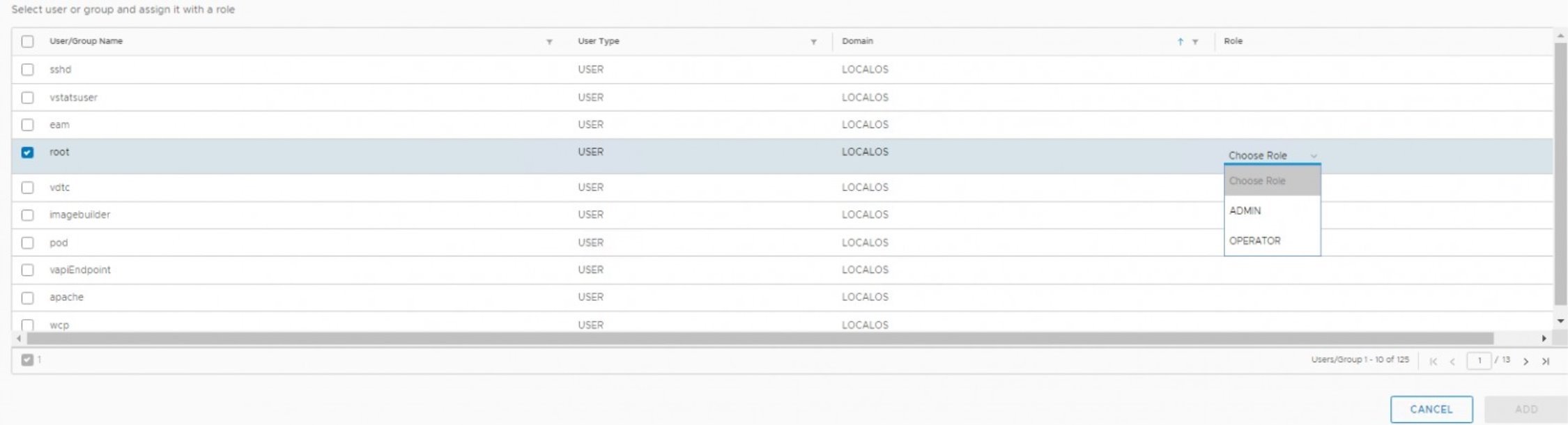
As such, identity sources from Active Directory, LDAP and Open LDAP added to vCenter will appear here. Note that there are three roles defined in SDDC Manager, ADMIN and OPERATOR and VIEWER.
SDDC Manager: Repository Settings
Once SDDC Manager is setup, users are required to enter ‘My VMware’ account details to enable software bundle downloads. This may require configuration of a proxy in some environments.
Navigate to the ‘Repository Settings’ panel on the left of the interface and enter your myvmware account details:

Once bundles are available to download, the ‘Bundles’ panel will populate:
See the section on ‘LCM Management’ for further information on managing bundles.
SDDC Manager: Backup Configuration
It is recommended that the NSX managers are backed up to an external destination (currently SFTP is supported). Navigate to ‘Backup Configuration’ on the panel on the left and click on ‘Register External’:

Enter the IP address, port, user credentials, etc. for the external destination:

Section 2 VCF Infrastructure Deployment / Day 1.
Workload Domain Creation
Workload Domain Overview
In VMware Cloud Foundation, a “workload domain” (or WLD) is a policy-based resource container with specific availability and performance attributes that combines compute (vSphere), storage (vSAN, NFS, VMFS or vVOLs), and networking (NSX-T) into a single consumable entity. Each workload domain may be created, expanded, and deleted as part of the SDDC lifecycle operations, and may contain one or more clusters of physical hosts.
Every Cloud Foundation deployment begins with provisioning a management workload domain, which hosts SDDC components necessary for Cloud Foundation to function. After the management workload domain is successfully deployed, SDDC Manager may be used to deploy additional Virtual Infrastructure VI) workload domains to host VM and container workloads. Each VI workload domain is managed by a corresponding vCenter instance, which resides within the VCF management domain; other management- related workloads associated with each workload domain instance may also be deployed within the management domain.
Cloud Foundation uses and is validated against vSAN, NFS v3, and VMFS on FC for principal storage. The management domain requires vSAN for principal storage. You can use vSAN, NFS v3, or VMFS on FC for principal storage with VI workload domains. The type of principal storage used by the initial vSphere cluster in a VI workload domain is defined when the VI workload domain is created. For VI workload domains, you can add vSphere clusters that use a different type of principal storage than the type selected for the initial cluster when the VI workload domain was created. After a vSphere cluster has been deployed you cannot change to another storage type.
Each VCF workload domain requires a minimum of three (3) hosts. Exact requirements vary depending on the workload domain type the host resides in. See the table below for details.
|
Component |
Requirements
• For vSAN-backed VI workload domains, three (3) compatible vSAN ReadyNodes are required. For information about compatible vSAN ReadyNodes, see the VMware Compatibility Guide. • For NFS-backed workload domains, three (3) servers compatible with the vSphere version included with the Cloud Foundation BOM are required. For information about the BOM, see the Cloud Foundation Release Notes. For compatible servers, see the VMware Compatibility Guide. • For VMFS on Fibre Channel backed workload domains, three (3) servers compatible with the vSphere version included with the Cloud Foundation BOM are required. For information about the BOM, see the Cloud Foundation Release Notes. In addition, the servers must have supported Fibre Channel (FC) cards (Host Bus Adapters) and drivers installed and configured. For compatible servers and Fibre Channel cards, see the VMware Compatibility Guide.
Servers within a cluster must be of the same model and type.
• For vSAN-backed VI workload domains, supported vSAN configurations are required. • For NFS-backed VI workload domains, configurations must be compatible with the vSphere version included with the Cloud Foundation BOM. For more information about the BOM, see the Cloud Foundation Release Notes. • For VMFS on Fibre Channel backed workload domains, configurations must be compatible with the vSphere version included with the Cloud Foundation BOM. For information about the BOM, see the Cloud Foundation Release Notes.
• Two 10GbE (or faster) NICs. Must be IOVP certified. • (Optional) One 1GbE BMC NIC |
|
Servers |
|
|
CPU, Memory, and Storage |
|
|
NICs |
In this proof-of-concept guide, we will focus on configuration of workload domains with vSAN-backed storage. For configuration of NFS or FC-backed storage, please consult the Cloud Foundation documentation in conjunction with documentation from the NFS or FC storage array vendor.
- To commission a host in SDDC manager, navigate to the Inventory > Hosts view, and select ‘Commission Hosts’ at the top right of the user interface.
- Verify that all host configuration requirements have been met, then click ‘Proceed’.
- On the next screen, add one or more hosts to be commissioned. These may be added via the GUI interface, or alternatively may be added through a bulk import process. To add hosts via the GUI, ensure the ‘Add new’ radio button has been selected, and fill in the form. Then, click ‘Add’.
- Alternatively, to bulk import hosts, click the ‘JSON’ hyperlink to download a JSON template for entering host information. After entering host details into the .JSON file, save it locally and select the ‘Import’ radio button. Then, click ‘Browse’ to select the .JSON file, and click ‘Upload’ at the lower right to upload the file to SDDC Manager.
- When all hosts for commissioning are added, confirm the host fingerprints by selecting all hosts in the ‘Hosts Added’ table by clicking the grey circle with a checkmark located beside each host fingerprint listed in the ‘Confirm Fingerprint’ column. When the circle turns green, click the ‘Validate All’ button located near the upper right corner of the table.
- After clicking ‘Validate All’, wait for the host validation process to complete. This may take some time. When the validation process completes, verify that all hosts have validated successfully, then click ‘Next’ to advance the wizard. On the final screen of the wizard, review the details for each host, then click ‘Commission’ to complete the process.
To configure a new VI workload domain, a minimum of three unused vSphere hosts must be available in the Cloud Foundation inventory.
Further, the host management interfaces should be accessible by SDDC Manager, and appropriate upstream network configurations should be made to accommodate vSphere infrastructure traffic (i.e., vMotion, vSAN, NSX-T, management traffic, and any required VM traffic).
If available hosts that meet requirements are not already in the Cloud Foundation inventory, they must be added to the inventory via the Commission Hosts process. Hosts that are to be commissioned should not be associated with a vCenter and should not be a member of any cluster. Additionally, prior to commissioning, each host must meet certain configuration prerequisites:
- Hosts for vSAN-backed workload domains must be vSAN compliant and certified per the VMware Hardware Compatibility Guide. BIOS, HBA, SSD, HDD, etc. must match the VMware Hardware Compatibility Guide.
- Host has a standard virtual switch back by two (2) physical NIC ports with a minimum 10 Gbps speed. NIC numbering should begin with vmnic0 and increase sequentially.
- Host has the drivers and firmware versions specified in the VMware Compatibility Guide.
- Host has ESXi installed on it. The host must be preinstalled with supported versions listed in the BOM. SSH and syslog are enabled on the host.
- Host is configured with DNS server for forward and reverse lookup and FQDN. Hostname should be same as the FQDN.
- Management IP is configured to first NIC port. in a multi-nic enviroment. you can manually specify the nics used via the API. For the mgmt domain/in CB, you can configure this on the bring-up json.
- Ensure that the host has a standard switch and the default uplinks with 10Gb speed are configured starting with traditional numbering (e.g., vmnic0) and increasing sequentially.
- Host hardware health status is healthy without any errors. All disk partitions on HDD / SSD are deleted.
- Ensure required network pool is created and available before host commissioning.
- Ensure hosts to be used for VSAN workload domain are associated with vSAN enabled network pool. Ensure hosts to be used for NFS workload domain are associated with NFS enabled network pool.
- Ensure hosts to be used for VMFS on FC workload domain are associated with NFS or vMotion only enabled network pool.
Workload Domain Creation Steps
- To create a VI workload domain, navigate to the Workload Domains inventory view. Then, at the top right of the screen, click “+Workload Domain”, then select VI – Virtual Infrastructure from the dropdown.
- Choose the storage type to use for this workload domain, vSAN, NFS, or VMFS on Fiber Channel (this cannot be changed later).
- Enter configuration details for the workload domain. Note that information will be used to provision a new instance of vCenter. This instance’s VM resides in within the Management workload domain, and manages the clusters associated with its respective VI workload domain. Please ensure that valid forward and reverse DNS entries for the vCenter FQDN are configured, then click ‘Next’.
- On the next screen, choose the version of NSX to deploy, and enter the deployment parameters. Ensure that forward and reverse DNS entries for NSX Manager FQDNs are be configured, and that the correct NSX software bundles have been downloaded on SDDC Manager. Then, click ‘Next’.
- On the fourth screen in the wizard, configure the vSAN default Failures To Tolerate (FTT). Enabling the Dedupe and Compression feature for all-flash clusters is optional. Then, click ‘Next’.
- The next step requires selecting available hosts from inventory to add to the workload domain. If there are no hosts available, please follow the instructions above for commissioning hosts within SDDC Manager. VMware recommends deploying no less than 4 hosts per workload domain in order to ensure that compliance with vSAN FTT=1 policy may be maintained if a vSAN cluster host is offline. However, in cases where hosts available for the POC are limited, it is acceptable to construct a workload domain with the minimum three (3) required hosts, then later add an additional host for the purposes of demonstrating workload domain expansion functionality. For clusters supporting vSAN FTT polices greater than one (1) (i.e., FTT=2 or FTT=3), it is recommended to deploy at least one additional host above the minimum required for policy compliance. See the vSAN Design and Sizing guide for additional details. After selecting the hosts to be added, click ‘Next’.
- Now, choose licenses available within SDDC Manager for the workload domain. If no applicable licenses are present, please add them to SDDC Manager (Administration > Licensing) then click ‘Next’.
- Finally, review the deployment summary, then click ‘Finish’ to launch the deployment.
To view an interactive demonstration of this process with step-by-step instructions, please visit Create Workload Domain (NSX-T and vSAN) in the VCF resource library on TechZone.
Review Workload Domain Components
Components deployed during the workload domain creation process may be viewed within SDDC Manager. To view these components, navigate to Inventory > Workload Domains within SDDC Manager, then click the name of the workload domain you would like to inspect.
To view an interactive walk-through of VCF SDDC components, please visit the Review Workload Domain Components demonstration https://core.vmware.com/?share=isim_demo2129 in the VCF resource center on core.vmware.com.
Expand Workload Domain Cluster
To expand the host resources available within a workload domain, the SDDC Manager interface is used to move one or more unused hosts from the SDDC Manager inventory to a workload domain cluster.
Before attempting to add additional hosts to a workload domain, verify that ‘Unassigned’ hosts are available in the SDDC Manager Inventory. If no hosts are presently ‘Unassigned’, please follow the host commissioning process to make one or more hosts available for use.
To view an interactive demonstration of this process with step-by-step instructions, please visit the Expand Cluster demonstration https://core.vmware.com/?share=isim_demo2127 in the VCF resource center on core.vmware.com.
NSX Configuration Overview: VI Workload Domain(s)
When creating a VI workload domain, NSX-T is deployed to support its networking stack. There are prerequisites for deploying NSX-T; please refer to the VCF Product Documentation for details.
A cluster of three NSX-T Manager nodes is deployed by default when an NSX-T based workload domain is created. On the workload domain page, select the summary view, and then

If an NSX-T Edge Cluster is also created, it will be visible and associated to the workload domain instance of NSX-T.
Click the FQDN of the NSX-T Cluster. This will open a new browser tab and automatically log into one of the NSX-T Manager instances.

Confirm that the NSX-T management cluster is in ‘STABLE’ state. Also verify that the Cluster Connectivity for each node is ‘Up’:

To review the Transport Zones configured, Select System > Fabric > Transport zones
There are two Overlay transport zones and one VLAN transport zone.
Hosts associated with this workload domain are connected to the default NSX-T overlay for the workload domain, in this case four hosts

Select System > Fabric > Nodes and select Host Transport Nodes tab in the “Managed by” drop-down list to show all transport nodes in the cluster associated with the vCenter instance associated with the workload domain.
Ensure the ‘Configuration’ is set to ‘Success’ and “Node Status” is ‘Up’ for each node:

vCenter
All NSX Managers for new workload domains are deployed on the Management workload domain resource pool. From the management vCenter, go to Hosts and Clusters and expand the resource pool mgmt-rp

vSphere Networking
With previous versions of NSX-T, installing NSX-T required setting N-VDS and migrating to from vDS. Now it is possible to use a single vSphere Distributed Switch for both NSX-T 3.0 with vSphere 7 networking. When installing NSX-T 3.0 it can run on top of the existing vDS without needing to move pNICs to N-VDS.
Note: When NSX-T is associated with the vSphere VDS it will be updated on the summary page that it is managed by NSX-T instance.
NSX-T Edge Cluster Deployment
You can add multiple NSX-T Edge clusters to workload domains for scalability and resiliency. However, multiple Edge clusters cannot reside on the same vSphere cluster.
NSX-T Data Centre supports a maximum of 16 Edge clusters per NSX Manager cluster and 8 Edge clusters per vSphere cluster.
The north-south routing and network services provided by an NSX-T Edge cluster created for a workload domain are shared with all other workload domains that use the same NSX Manager cluster.
For more information, please review VCF documentation https://docs.vmware.com/en/VMware-Cloud-Foundation/4.1/com.vmware.vcf.admin.doc_41/GUID-8FA66DA3-3166-426B-84A8-C45FA7651658.html
So, in this POC guide we will have already deployed an additional workload domain.
The purpose of this document is to walk through the configuration to understand the network requirements and finally to check and validate that the edge(s) were deployed successfully
Prerequisites
As per the documentation
Note: Please refer to official documentation for detailed steps on https://docs.vmware.com/en/VMware-Cloud-Foundation/4.1/com.vmware.vcf.admin.doc_41/GUID-D17D0274-7764-43BD-8252-D9333CA7415A.html. Official documentation should supersede if it differs from guidance documented here.
Below is a guided deployment with screenshots to augment the deployment.
- Separate VLANs and subnets are available for NSX-T Host Overlay (Host TEP) VLAN and NSX-T Edge Overlay (Edge TEP) VLAN. A DHCP server must be configured on the NSX-T Host Overlay (Host TEP) VLAN.
- You cannot use DHCP for the NSX-T Edge Overlay (Edge TEP) VLAN.
- NSX-T Host Overlay (Host TEP) VLAN and NSX-T Edge Overlay (Edge TEP) VLAN are routed to each other.
- For dynamic routing, set up two Border Gateway Protocol (BGP) Peers on Top of Rack (ToR) switches with an interface IP, BGP autonomous system number (ASN), and BGP password.
- Reserve a BGP ASN to use for the NSX-T Edge cluster’s Tier-0 gateway.
- DNS entries for the NSX-T Edge nodes are populated in the customer-managed DNS server.
- The vSphere cluster hosting an NSX-T Edge cluster must include hosts with identical management, uplink, host TEP, and Edge TEP networks (L2 uniform).
- You cannot deploy an Edge cluster on a vSphere cluster that is stretched. You can stretch an L2 uniform vSphere cluster that hosts an Edge cluster.
- The management network and management network gateway for the Edge nodes must be reachable.
- Workload Management supports one Tier-0 gateway per transport zone. When creating an Edge cluster for Workload Management, ensure that its overlay transport zone does not have other Edge clusters (with Tier-0 gateways) connected to it.
Deployment Planning
As a proof of concept, we will deploy a new Edge Cluster to an already deployed workload domain called wld01.
- We will deploy a small Edge Node Form Factor: 4 GB memory, 2 vCPU, 200 GB disk space. The NSX Edge Small VM appliance size is suitable for lab and proof-of-concept deployments.
Note: You cannot change the size of the edge form factor after deployment. Only use SMALL for lab or proof of concepts. For Tanzu (Kubernetes) please use LARGE
- We will deploy two Edges in Active-Active High Availability Mode (In the active-active mode, traffic is load balanced across all members and If the active member fails, another member is elected to be active)
We have gathered the following details prior to deployment
- ASN number: 65004 for Tier-0 BGP
- ToR Switch IP addresses and subnets
- NSX-T Overlay VLAN 1252 (routable to host overlay)
- Static IP addresses for Edge Overlay VLAN 1252
- Edge Uplinks VLAN 2081 and 2082. (for connectivity to Top of Rack
- Switch Static IP addresses for VLAN 2081 and 2082
NSX-T Edge deployment Step by Step Procedure
From SDDC manager Click on Workload Domains, select a workload domain, and click on Actions Chose Click Add Edge Cluster

Click Begin to walk through the wizard

The following walk-through demo can be reviewed here to understand the process. Please navigate to Add NSX-T Edge Cluster https://core.vmware.com/?share=isim_demo2119
Validation of NSX-T Edge Cluster
From SDDC Manager UI the new edge cluster is listed on the Workload Domain summary
Validation is also explored by reviewing the walk through demo can be reviewed here to understand the process please navigate to demo Add NSX-T Edge Cluster https://core.vmware.com/?share=isim_demo2119 Once the demo is started, navigate to step 47 of the demo

From the SDDC manager shortcut launch the NSX-T web interface
Click System > Fabric Edge Transport Nodes to see the edge node details. We can see edge01- wld01.vcf.sddc.lab and edge02-wld01.vcf.sddc.lab deployed

From the top menu click Networking to view the Tier-0 and Tier-1 dashboards
We can see from the dashboard. the Tier-0 gateways. This is responsible for North-South Routing. We can see BGP is enabled and a Peer is configured. The Tier-1 gateway is used for East-West traffic.
To view the topology layout between Tier-1, Tier-0 and the outside physical infrastructure, Select Network Topology
We can see 192.168.17.4/24, 192.168.16.4/24 192.168.17.5/24 and 192.168.16.5/24 represent the IP addresses on the edges that are peered to the of rack AS 65001.

To verify BGP connectivity and peering status to the top of rack switches
- Navigate back to Network Overview, select Tier-0 Gateways, select the Tier-0 Edge, edge01-t0, to expand on the details
- Click on BGP to expand
- Click on 2 for BGP neighbor details (as we have two neighbors configured)
We can see the status of both Top of Rack BGP Peers. Status of Success indicates peering has been successfully established.

vSphere
The NSX-T Edge Cluster will be deployed on the associated workload domain. And Edge Cluster resource pool is created, and the edges are deployed onto the workload domain cluster, in this case wld01
Note: the vCenter and NSX-T unified controllers are deployed on the Management Domain vSphere Cluster
To view the edges from a vSphere perspective, login to the vSphere Client, navigate from host and clusters to the vCenter instance associated with the workload domain, expand the cluster and resource pool to inspect the NSX-T Edges.

vSphere Networking and vDS details
Two additional vDS port groups are created on the workload domain vDS
from the vSphere Web client, navigate to vSphere Networking, the workload domain vCenter, and the associated VDS to inspect the edge port-groups.

Edge vNICs
Each Edge will have a similar VM networking configuration
Network adapter 1 is for the management network connectivity (MGMT VLAN 0) Network Adapter 2 is associated with the Edge Uplink (VLAN 2081) Network Adapter 2 is associated with the Edge Uplink (VLAN 2082)
This configuration can be explored on the summary of the Edge Virtual Machine appliance.
Reusing an existing NSX-T manager for a new workload domain
If you already have an NSX Manager cluster for a different VI workload domain, you can reuse that NSX Manager cluster.
In order to share an NSX Manager cluster, the workload domains must use the same update manager mechanism. The workload domains must both use vSphere Lifecycle Manager (vLCM), or they must both use vSphere Update Manager (VUM).
Note: - Do not share an NSX Manager cluster between workload domains catering to different use cases that would require different NSX-T Edge cluster specifications and configurations.
Please review the click through demo that complements this guide Add Workload Domain with NSX Manager Reuse https://core.vmware.com/?share=isim_demo2181 The demo first reviews an existing workload domain and then walks through deploying a new workload domain. To quickly go through this scenario, we will go through the main parts of the demo
From SDDC Manager start the deploy wizard for a new VI - Virtual Infrastructure to deploy workload domain,
Once new workload domain wizard is launched, add the entries for the workload domain name and new vCenter instance
Instead of deploying a brand new NSX-T Instance, we will Re-use the NSX-T Instance associated with an existing workload domain, in our case wld01
The VLAN ID for the pre-existing NSX-T host overlay needs to be validated

All NSX-T entries are greyed out as we are using the NSX-T instance associated with wld01 which SDDC Manager is already aware of

The following resources will be pre-fixed workload domain name wld01
- vSphere Distributed Switch
- Resource Pool
- Distributed port-group vSAN
- Distributed port-group vMotion
- vSAN Datastore

Once the Workload domain has been deployed it will simply appear as a new workload domain on SDDC Manager but associated with the NSX-T instance belonging to wld01.
From a vSphere perspective, a new vCenter Server is deployed, a new datacenter and cluster object is created, and hosts added and configured

We can also observe the vCenter server appliance vcenter-wld02.vcf.sddc.lab is hosted on the management workload domain with no further additional NSX-T instances.

vSphere Networking comprises of a vDS and 3 port-groups for mgmt, vSAN and vMotion.

NSX-T

The vCenter Server is registered as an additional compute manager to the existing NSX-T instance (as specified on the new workload domain wizard)
The vSphere hosts are configured as Host Transport nodes associated with that vCenter

However, they are added to the same transport zone as the transport Nodes in the first workload domain, wld01, i.e., overlay-tx-nsx-wld01.vcf.sddc.lab

Section 3 vRealize Suite Deployment
VCF 4.1 now supports vRealize Suite 2019
VMware Cloud Foundation 4.1 introduces an improved integration with vRealize Suite Lifecycle Manager. When vRealize Suite Lifecycle Manager in VMware Cloud Foundation mode is enabled, the behavior of vRealize Suite Lifecycle Manager is aligned with the VMware Cloud Foundation architecture.
Note: Please refer to official documentation for detailed steps on https://docs.vmware.com/en/VMware-Cloud-Foundation/4.1/com.vmware.vcf.admin.doc_41/GUID-8AD0C619-6DD9-496C-ACEC-95D022AE6012.html. Official documentation should supersede if it differs from guidance documented here.
Below is a guided deployment with screenshots to augment the deployment.
Prerequisites
- You must deploy vRealize Suite Lifecycle Manager before you can deploy other vRealize Suite products on Cloud Foundation
- You must then deploy Workspace ONE Access before you can deploy the individual vRealize Suite products on Cloud Foundation.
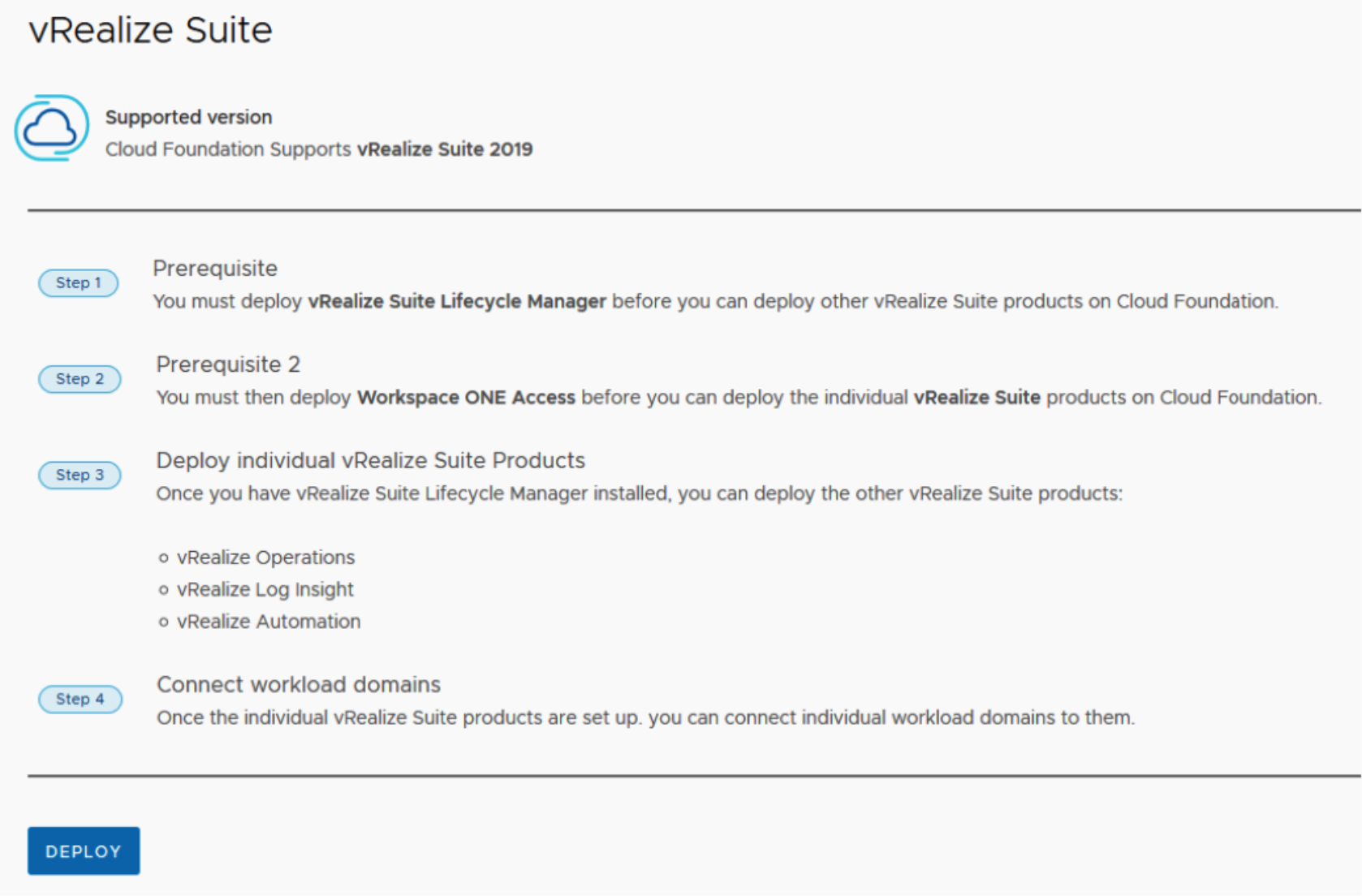
Once you have vRealize Suite Lifecycle Manager installed, you can deploy vRealize Suite products such as
- vRealize Operations
- vRealize Log Insight
- vRealize Automation
Once Deployed you can connect individual workload domains to them.
For the purposes of this POC Guide we will cover
- vRealize Life Cycle Manager
- vRealize Workspace One Access
- vRealize Operations
- vRealize Log Insight
Deploying vRealize Suite Life Cycle Manager
vRealize Suite Lifecycle Manager introduces a functionality where you can enable VMware Cloud Foundation mode in vRealize Suite Lifecycle Manager 8.1.
Any operation triggered through vRealize Suite Lifecycle Manager UI is aligned with the VMware Cloud Foundation architecture design.
When a VMware Cloud Foundation admin logs in to vRealize Suite Lifecycle Manager, you can perform normal regular operations like any vRealize Suite Lifecycle Manager user. The VMware Cloud Foundation user can view applications like, User Management, Lifecycle Operations, Locker, Marketplace, and Identity and Tenant Management but with some limitations.
You can perform the same set of operations with limited access to the latest version of the vRealize Suite products. To perform a regular operation, you have to specify the license and certificate settings using the Locker in vRealize Suite Lifecycle Manager UI.
Some of the features that are used by VMware Cloud Foundation from vRealize Suite Lifecycle Manager.
- Binary mapping. vRealize Suite Lifecycle Manager in VMware Cloud Foundation mode has a sync binary feature from which you can poll the binaries from the VMware Cloud Foundation repository and maps the source automatically in vRealize Suite Lifecycle Manager.
- Cluster deployment for a new Environment. You can deploy vRealize Automation, vRealize Operations Manager, vRealize Log Insight in clusters, whereas in VMware Identity Manager, you can only deploy both cluster and single node, and later expand to a cluster.
- Product Versions. You can only access the versions for the selected vRealize products that are specifically supported by VMware Cloud Foundation itself.
- Resource Pool and Advanced Properties. The resources in the Resource Pools under the Infrastructure Details are blocked by the vRealize Suite Lifecycle Manager UI, so that the VMware Cloud Foundation topology does not change. Similarly, the Advanced Properties are also blocked for all products except for Remote Collectors. vRealize Suite Lifecycle Manager also auto-populates infrastructure and network properties by calling VMware Cloud Foundation deployment API.
vRSLCM Perquisites
To Deploy SDDC manager you will need
- vRSLCM downloaded via SDDC Manager.
- AVN networks ensuring routing between AVNs and Management networks is functioning correctly.
- IP address and DNS record for vRealize Suite Life Cycle Manager.
- Free IP address in AVN Segment for Tier 1 gateway.
- DNS and NTP services available from AVN Segments.
Note: Please refer to official documentation for detailed steps on https://docs.vmware.com/en/VMware-Cloud-Foundation/4.1/com.vmware.vcf.admin.doc_41/GUID-8AD0C619-6DD9-496C-ACEC-95D022AE6012.html. Official documentation should supersede if it differs from guidance documented here.
Below is a guided deployment with screenshots to augment the deployment.
Step by Step Deployment
From SDDC Manager, select vRealize Suite and click Deploy.
AVN Network Segment, Subnet, gateway, DNS and NTP settings should be prepopulated by SDDC Manager.

Click Next
For NSX-T Tier 1 Gateway, enter in free IP Address on AVN Segment. Do not use the same IP address as another IP address on the AVN segment. It must be a free and unused IP address
The default System Administrator userid is vcfadmin@local

vRSLCM Deployment task can be monitored via SDDC Manager Tasks

Once vRSLCM is deployed successfully the next step is to license vRealize Suite

Add vRealize Suite License key.
Add license key to vRSLCM
- Login to vRSLCM with vcfadmin@local (you may have to change password on initial login)
- Navigate to Locker and Select License.
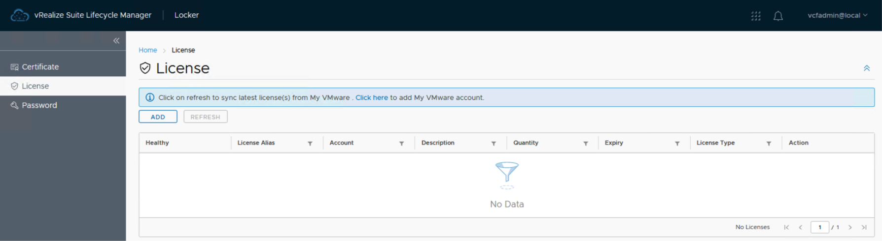
3. Select Add license and validate. Once Validated select Add.


Deploying VMware Identity Manager
You must deploy Workspace ONE via vRealize Suite Lifecycle Manager
Requirements are
- Workspace ONE Access software bundle is downloaded under Bundle Management on SDDC Manager
- vRealize Suite License key
- 5 static IP address with FQDNs (forward and reverse lookup)
- CA signed certificate or self-signed certificate
- vcfadmin@local password
Note: Please refer to official documentation for detailed steps on https://docs.vmware.com/en/VMware-Cloud-Foundation/4.1/com.vmware.vcf.admin.doc_41/GUID-8AD0C619-6DD9-496C-ACEC-95D022AE6012.html. Official documentation should supersede if it differs from guidance documented here.
In this POC scenario we will deploy a clustered Workspace one instance , so we will require an IP address for Cluster VIP, Database IP for 3 IP addresses for each cluster member and a certificate which includes the FQDN names and IP addresses of each member, for example:
|
IP (AVN Segment) |
FQDN |
Purpose |
|
192.168.11.13 |
m01wsoa.vcf.sddc.lab |
Cluster VIP |
|
192.168.11.14 |
m01wsoa1.vcf.sddc.lab |
Cluster Node 1 |
|
192.168.11.15 |
m01wsoa2.vcf.sddc.lab |
Cluster Node 2 |
|
192.168.11.16 |
m01wsoa3.vcf.sddc.lab |
Cluster Node 3 |
|
192.168.11.17 |
n/a |
Database IP |
Ensure binaries are downloaded via SDDC manager. vRSLCM should map product binaries to SDDC repro as part of deployment.
To verify, in the navigation pane, select Lifecycle management > Bundle management.
Click the Bundles tab, locate the Workspace ONE Access install bundle. Click Download bundle if not present

Login to vRSLCM with vcfadmin@local
Navigate to Lifecycle Operations > Settings > Binary Mappings
Ensure Workspace ONE OVA is present. You may have to synch binaries from SDDC Manager if OVA is not present

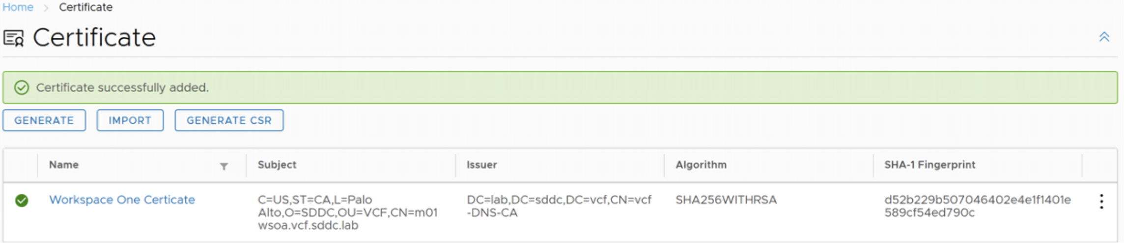
Add Workspace ONE Certificate
You can generate a self-signed certificate or Generate CSR for an external CA
In this scenario we are going to generate a CSR to create a CA signed certificate.
Login to vRSLCM with vcfadmin@local
Navigate to Locker, Select Certificate and Generate.


Add Name, CN name (this is the IP of Workspace ONE Cluster IP)
If Workspace ONE is going to be deployed in cluster mode add Cluster IP, and cluster members (FQDN) and IP addresses for each member.
It is also possible to generate a certificate signing request to submit to an external CA. Click Generate CSR.

You will be prompted to download and save the .pem file which includes private key and signing request once all fields have been filled out
Save the file, so it can be retrieved later
The CSR can be signed by an appropriate CA. If using an internal Microsoft CA, paste the CSR PEM file contents to the CA to generate a new certificate request.

Download Certificate and Certificate chain and use Base 64 Encoding

Once Certificate chain is generated and downloaded (Base 64 encoded), return to vRSLCM > Lifecycle Operations > Locker > Certificate and Click Import

To import the generated Certificate. Provide a Name, e.g., Workspace ONE Certificate, paste the Private Key from the CSR request and Paste the certificate chain generated earlier in the procedure
Note: The Private Key and Certificate can be combined into a single file to simplify the process.
Add the Private Key first then append the certificate chain to a file

In vRealize Suite Lifecycle Manager 8.X stores all the passwords that are used across the vRealize Suite Lifecycle Manager. You can configure a password at the locker level and are retrieved from the UI.
Login to vRSLCM with vcfadmin@local
Navigate to Locker, and Select password, and select Add

The default password must be a minimum of eight characters.
Add the details for Password alias, password itself Description and Username


Install Identity Manager
Login to vRSLCM with vcfadmin@local
Navigate to Lifecyle Operations, Create Environment. Use the global environment as is already populated with the vCenter details
Add Administrator email and Default Password.
Note: if Password is not already configured in Locker, a new password can be created by clicking on the “Plus” Sign to add
Select Datacenter, which should already be populated from the Management workload domain from drop down list

Opt in or out of VMware Customer Experience Improvement program and click Next
Select VMware Identity Manager and in this scenario, we are selecting clustered mode which means we will need 5 IP addresses in AVN Network Segment, ensure corresponding FQDN are created. Click Next to continue

Accept the EULA, click Next.
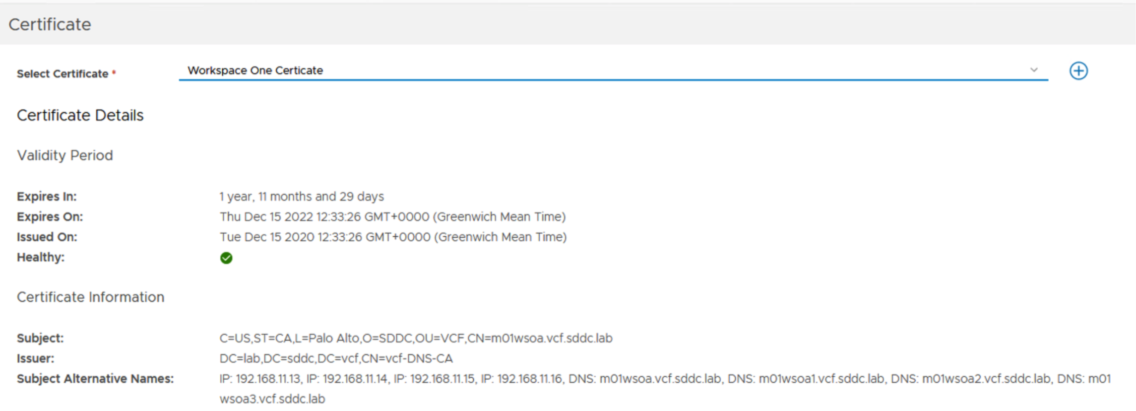
Select the Certificate that was created earlier (or create a new certificate).
Infrastructure details should already be populated from SDDC manager. Since we are deploying to vSAN, chose Thin mode, which means the appliances will be deployed thinly provisioned using the default vSAN Storage Policy, click Next.

Network Details should also be pre-populated from AVN details, click Next

VMware Identity Manager Details must be entered for certificate, password, Cluster IP, Database IP, and Cluster members.
Below are screenshots for each screen to illustrate the number of inputs.


Run Pre-check before deployment to validate inputs and infra.

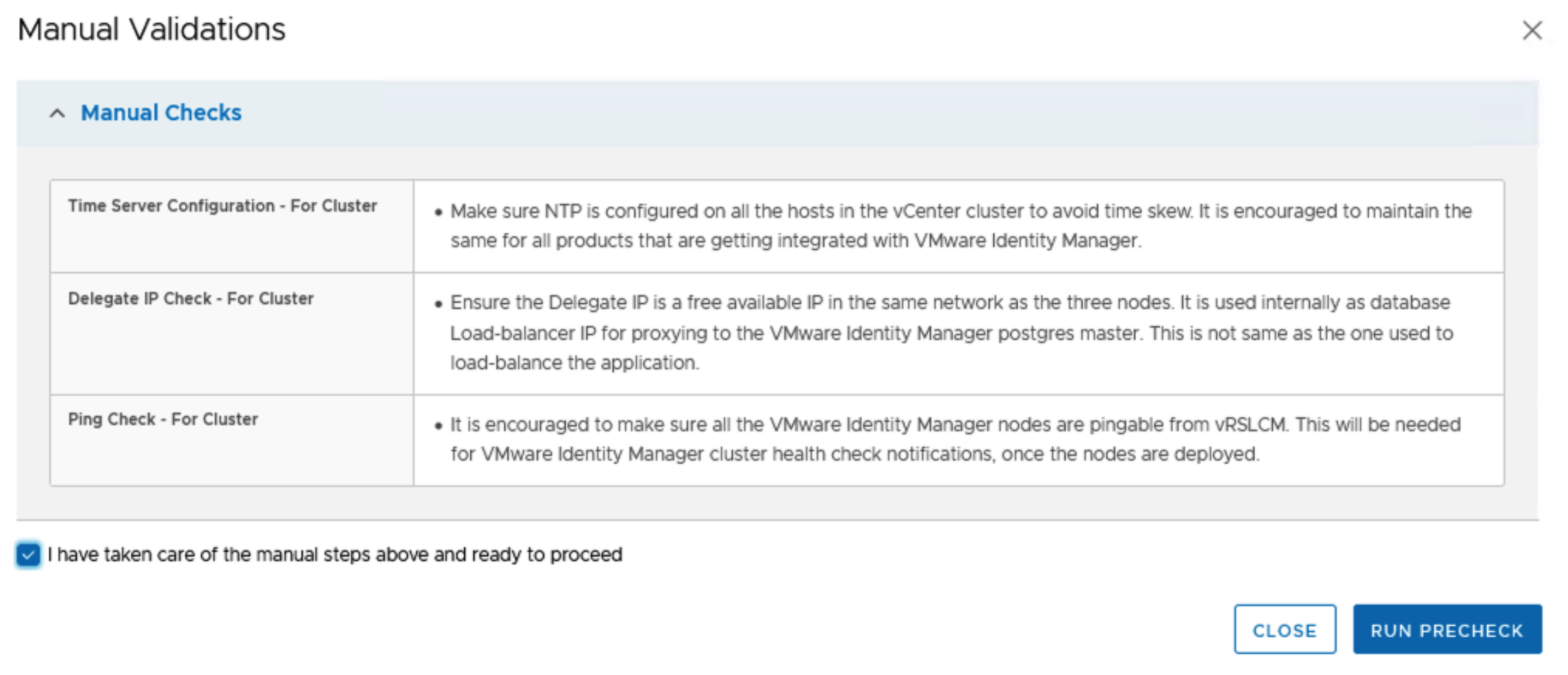
Ensure all pre-checks pass validation

The pre-check report can be downloaded in PDF format or pre-check can be re-run.
Click Next.
At this point you are ready to submit, a json file can be downloaded to deploy programmatically. Pre-check can be re-run. Or progress can be saved now to submit later. Review settings and click Submit.

Deployment progress can be monitored from vRSLCM, SDDC manager and vCenter

SDDC Manager
NSX-T load balancer will be deployed from SDDC manager as part of the deployment, this can be monitored on SDDC Manager tasks.

vCenter
Workspace one OVAs will be deployed on the management cluster
Once Deployed Successfully the task should be marked as complete from vRSLCM > Life Cycle Operations > Requests.

Verify Workspace ONE Identity Manager
Navigate to vRSLCM > Lifecycle Operations > Environments
Click on global environment and View details

Trigger inventory sync to trigger sync from vRSLCM to VIDM and to SDDC Manager
This task can be monitored from Requests on SDDC Manager.

From SDDC manager Dashboard Navigate to vRealize Suite. Details of vRSLCM and Workspace One access is registered

Connect to Workspace one access and connect using the credentials specified during install


Deploying vRealize Operations
With vRSLCM and Workspace One deployed you are now able to deploy vROPS
In this POC scenario we will deploy a 3 node vROPs cluster (Master Replica ad Data node)
Note: Please refer to official documentation for detailed steps. Official documentation should supersede if it differs from guidance documented here.
vROPS Requirements
- vRealize Operations Manager binaries
- vRealize Operations Manager bundle synched to vRSLCM product binaries
- at least 4 IP addresses for vROPS cluster IP, Master, Replica and data node.
- Appropriate vRealize License Key
- Certificate (self-signed or signed by CA)
- Password setup
For example, we need the following IP addresses with FQDN (forward and reverse lookups
|
IP (AVN Segment) |
FQDN |
Purpose |
|
192.168.11.18 |
m01vrops.vcf.sddc.lab |
Cluster VIP |
|
192.168.11.19 |
m01vropsmaster.vcf.sddc.lab |
Master VROPS Node |
|
192.168.11.20 |
m01vropsreplica.vcf.sddc.lab |
VROPs Replica Node |
|
192.168.11.21 |
m01vropsdata1.vcf.sddc.lab |
Data Node |
vROPS Bundle Mapping
Verify VROPS 8.1.1 bundle has been downloaded on SDDC manager

If product binaries are displayed on vRSLCM a manual sync maybe necessary
Connect to vRSLCM and login with vcfadmin@local
Navigate to Lifecycle Operations > Settings > Binary Mappings

Similar to Workspace One, we may need to create a default password credential and Certificate for the vROPS Cluster
vROPS Default Password
From vRSLCM, Navigate to Locker > Password. Click Add
Below is a sample value for vROPS Passwords
|
Setting |
Value |
|
Password Alias |
vrops-root |
|
Password |
vrops-root-password |
|
Confirm Password |
vrops-root-password |
|
Password Description |
vROPS Root user |
|
Username |
root |

vROPs Certificate
Again, as per Workspace one we can generate a self-signed certificate or a CA signed certificate.
From vRSLCM, Navigate to Locker > Certificate > Generate for self-signed or Generate CSR for external CA
In our case as we already have an external CA, we will generate a CSR
Ensure to add the following CN name should match the cluster VIP and add the master, replica and data nodes in hostname and IP fields,
Here is a worked example
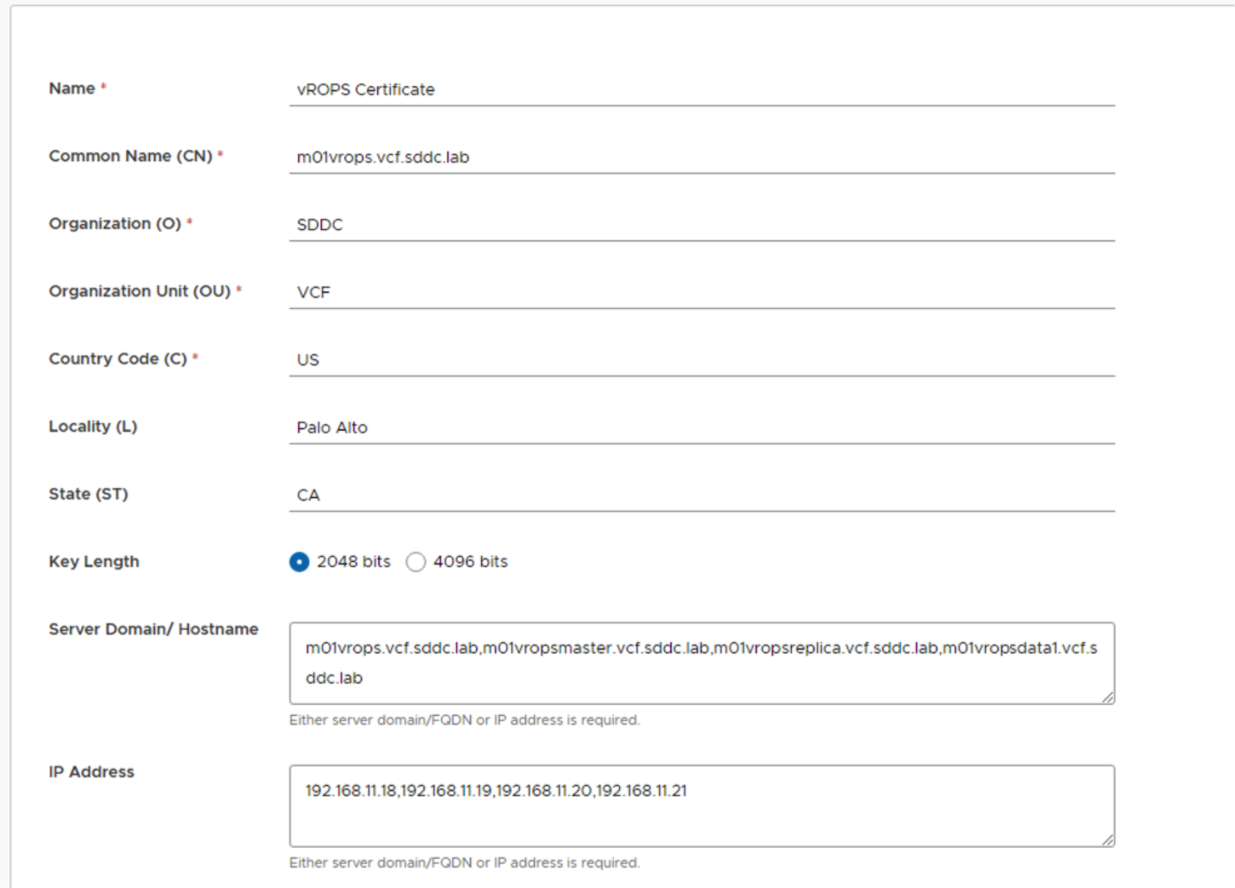
Click Generate if generating self-signed or Generate CSR
In this example we are generating a CSR.
Once the CSR is generated, sign with external CA and import certificate
Create Environment
We are going to setup a new environment for vROPs. This is in addition to the “globalenviroment” already created.
On vRSLCM dashboard click Lifecycle operations > Create Environment
In this case we will call the environment VCF-POC with default password of vrops-root we created earlier
The datacenter will be from the mgmt. workload domain

Select vROPS, New install with size of medium, and 3 nodes
For Product details enter the following, as per VVD guidance
We will implement
|
Setting |
Value |
|
Disable TLS version |
TLSv1, TLSv1.1 |
|
Certificate |
vROPS Certificate |
|
Anti-affinity / affinity Rule |
Enabled |
|
Product Password |
vrops-root |
|
Integrate with identity Manager |
Selected |

Select and Validate your license

Select the vROPS Certificate created earlier
![]()
vCenter Infrastructure details are pre-filled out and are displayed to be acknowledged, select Disk Mode to Thin and click next
As with Workspace One, networking details are pulled from SDDC Manager to reflect AVN networks, Click Next

For Cluster VIP add vROPS cluster FQDN

For Master Node component add FQDN (m01vropsmaster.vcf.sddc.lab) and IP address details.
The VM name can be changed to match particular naming conventions.

Click on advanced settings (highlighted) to review NTP and time zone Settings
For Replica Node component add Replica FQDN (m01vropsreplica.vcf.sddc.lab) and IP details

Click on advanced configuration Icon to add timezone details
For Data Node component add Data Node FQDN (m01vropsdata1.vcf.sddc.lab) and IP details

Click on advanced configuration Icon to add or check time zone details.
Click Next to continue and run RUN PRECHECK

Address any errors on Precheck and ensure all validations succeed

Review Summary and submit vROPS Deployment

Progress can also be tracked from Life Cycle Operations > Requests

Progress can also be tracked from SDDC Manager Tasks
As we can see as part of deployment vROPS will automatically configured to begin monitoring VCF management domain which includes vCenter, vSAN and Workspace One

Once deployed, the environment can be viewed from Lifecycle Operations > Environments
Progress

Click on view details to see the details

Clicking on TRIGGER INVENTORY SYNC will rediscover inventory of VCF management Domain.

Deploying vRealize Log Insight
Similar to vROPS we can now deploy vRealize Log insight in a new environment on vRSCLM
In this POC scenario we will deploy a 3 node vRealize Log Insight (vRLI) Cluster (one vRLI Master and two worker nodes)
Note: Please refer to official documentation for detailed steps. Official documentation should supersede if it differs from guidance documented here.
vRealize Log Insight Requirements
- vRealize Log Insight Binaries downloaded on SDDC Manager
- vRealize Log Insight bundle synched to vRSLCM product binaries
- at least 4 IP addresses for vRLI cluster IP, Master, two worker nodes.
- Appropriate vRealize License Key
- Certificate (self-signed or signed by CA) added to vRSLCM Locker
- Password added to vRSLCM locker
Sample IP addresses for vRli Cluster need the following IP addresses with FQDN (forward and reverse lookups
|
IP (AVN Segment) |
FQDN |
Purpose |
|
192.168.11.22 |
m01vrli.vcf.sddc.lab |
vRli Cluster IP |
|
192.168.11.23 |
m01vrlimstr.vcf.sddc.lab |
vRli Master Node |
|
192.168.11.24 |
m01vrliwrkr01.vcf.sddc.lab |
Worker Node 1 |
|
192.168.11.25 |
m01vrliwrkr02.vcf.sddc.lab |
Worker Node 2 |
vRealize Log Insight Bundle Download
Ensure install bundle for vRealize Log Insight 8.1.1 is downloaded on SDDC Manager and binaries are synched to vRSLCM

From vRealize Suite lifecycle manager, navigate to Lifecyle Operations > Settings > Binary Mappings
Ensure binaries are synched once vRealize Log Insight 8.1.1 has been downloaded to SDDC manager

vRealize Log Insight Default Password.
From vRSLCM, Navigate to Locker > Password. Click Add
|
Setting |
Value |
|
Password Alias |
vrli-admin |
|
Password |
vrli-admin-password |
|
Confirm Password |
vrli-admin-password |
|
Password Description |
Log Insight admin password |
|
Username |
admin |

vRealize Log Insight Certificate
Again, as per Workspace One and vROPS we can generate a self-signed certificate or a CA signed certificate
Since this is a cluster, we need a certificate for the following hostnames.
This IP range is based on the “Region A – Logical Segment” as part of VCF bring up using AVNs.
|
IP (AVN Segment) |
FQDN |
|
192.168.10.22 |
m01vrli.vcf.sddc.lab |
|
192.168.10.23 |
m01vrlimstr.vcf.sddc.lab |
|
192.168.10.24 |
m01vrliwrkr01.vcf.sddc.lab |
|
192.168.10.25 |
m01vrliwrkr02.vcf.sddc.lab |
This maps to Segment in NSX-T Logical Networks for the management domain

From vRSLCM, Navigate to Locker > Certificate > Generate for self-signed or Generate CSR for external CA

Either Generate a new certificate or import a certificate

vRealize Log Insight Create Environment
From vRSLCM dashboard go to Lifecycle Operations, then Create Environment
Add VCF POC Log Insight
|
Setting |
Value |
|
Environment name |
VCF POC vRli |
|
Administrator email |
|
|
Default Password |
Global Admin Password |
|
Select Datacenter |
m01-dc01 |

Select vRli with deployment type of Cluster

Click Next and Accept the EULA.
Select license, click Validate Association, and click Next

Select vRealize Log Insight Certificate that was created earlier and click next.
Verify infrastructure details, click next.
Note: NSX-T Segment should match VCF deployment)

Verify Network Details
Install Log Insight
For the purposes of this POC document we will select “Small “form factor for Node Size
Select Certificate, DRS Anti-affinity rule and integrate with Identity Manager

Add the IP addresses FQDN for Cluster VIP, Master, and two worker nodes


Run Precheck once all IP addresses and FQDN have been entered.

Address any issues and re-run pre-check

Once all prechecks are validated, review the configuration and initiate deployment
Deployment can be monitored by vRSLCM, vCenter and SDDC manager.
Once vRLI has been deployed, Navigate to SDDC Manager – vRealize Suite and verify vRealize Log Insight has been registered to VCF

Verify vRealize Log Insight connection to vRealize Operations Integration
Using a web browser navigate to vRli master node FQDN
Login as “admin”
Navigate to Administration > Integration, vRealize Operations
Ensure vROPs hostname and password are pointing to vROPS instance.
Click Test to verify setting

If not already enabled, enable alert management, launch in context and metric calculation and metric calculation.
Update content packs Navigate to Content Packs and updates as shown below.

Click Update All.
Section 4 Solution Deployment guidelines
Deploying vSphere 7.0 with Tanzu on VCF
vSphere with Tanzu provides the capability to create upstream compliant Kubernetes clusters within dedicated resource pools by leveraging Tanzu Kubernetes Clusters. Another advantage of vSphere with Tanzu is the ability to run Kubernetes workloads directly on ESXi hosts (vSphere Pods).
vSphere with Tanzu brings Kubernetes awareness to vSphere and bridges the gap between IT Operations and Developers. This awareness fosters collaboration between vSphere Administrators and DevOps teams as both roles are working with the same objects.

IT Operators continue to provision, view and monitor their virtual infrastructure as they have always done, but now with the Kubernetes awareness and insight that has eluded them in the past.
Developers can now deploy K8s and container-based workloads directly on vSphere using the same methods and tools they have always used in the public cloud. VMware vSphere with Tanzu provides flexibility as developers can choose to run pods native to ESXi (native pods) or inside purpose-build Kubernetes clusters hosted on top of namespaces configured on the vSphere clusters (Tanzu Kubernetes Clusters).
Both teams benefit by being able to use their existing tools, nobody has to change the way the work, learn new tools, or make concessions. At the same time, both teams have a consistent view and are able to manage the same objects.
Running vSphere with Tanzu on VMware Cloud Foundation (VCF) provides a best-in-class modern hybrid cloud platform for hosting both traditional and modern application workloads. VMware Cloud Foundation is a proven, prescriptive approach for implementing a modern VMware based private cloud. One of the key benefits of VCF is the advanced automation capabilities to deploy, configure, and manage the full VMware SDDC software stack including products such as vSphere with Tanzu, vSAN, and NSX among others.

Enabling vSphere with Tanzu
In order to enable vSphere with Tanzu it is necessary to complete a set of tasks. vSphere with Tanzu will be deployed in a Virtual Infrastructure Workload Domain; however, there is also an option to deploy vSphere with Tanzu on a Consolidated VCF deployment (Management Domain). For more information about vSphere with Tanzu supportability on VCF Management Domain please refer to this Blog Post and this White Paper. An NSX-T Edge Cluster will be required as well as tasks including enabling Workload Management, creating a content library, creating a namespace, deploying harbor, obtaining CLI Tools, creating guest clusters and deploying containers.
This is a workflow overview of the procedure from a two-persona perspective (IT Operator and Developer).

vSphere with Tanzu Requirements
The requirements are as below; a VI workload domain needs to be created with at least three hosts, backed by an NSX-T edge cluster.

vSphere with Tanzu on Consolidated Architecture Requirements
This is a special case whereby a K8s cluster can be stood up with just four hosts in total. In order to achieve this, an NSX Edge cluster must be created for the Management domain. Application Virtual Networks (AVNs) is now supported on the management domain together with K8s. The requirements are:
- Cloud Foundation 4.X deployed with one vSphere cluster on the management domain
- NSX-T configured (edge cluster (large form factor) created, hosts added. etc.)
- Enough capacity on the vSAN datastore for all components
NOTE: vSphere with Tanzu on consolidated architecture requires some important steps to be followed. Please refer to this document for step-by-step
instructions: https://blogs.vmware.com/cloud-foundation/files/2020/05/VMW-WP-vSphr-KUBERNETES-USLET-101-WEB.pdf
See this blog post for more
information: https://cormachogan.com/2020/05/26/vsphere-with-kubernetes-on-vcf-4-0-consolidated-architecture/

Creating VI Workload Domain

Creating a VI Workload Domain (VI WLD) falls in the IT Operator persona. The IT Operator will create a new VI WLD from SDDC by following the steps from the that particular POC section. However, there are a few aspects that should be taken into considerations when creating a VI WLD for vSphere with Tanzu use case.
Note that the VI WLD for Kubernetes should be created should be using VUM (as opposed to vLCM):

Requirements:
- Minimum of 3 hosts; 4 or more hosts recommended Licensed for vSphere with Tanzu
- New NSX-T Fabric
- VI WLD with VUM enabled (no vLCM)
- IP subnets for pod networking, service cluster, ingress and egress defined

Click HERE for a step-by-step demonstration.
Deploying Edge Cluster

Deploying a NSX Edge Cluster falls in the IT Operator persona. The IT Operator will deploy a new NSX Edge Cluster from SDDC by following the steps below. After creation, the NSX Manager UI can be used to manage such cluster.
Requirements:
- One edge cluster per domain
- Edge cluster type =” Workload Management “
- Two edge nodes Large form factor configured as active/active
From SDDC Manager, navigate to the VI Workload Domain, and click on the three vertical dots that appear when hovering on the domain name. Choose the "Add Edge Cluster":


Verify all the Prerequisites have been met and click Begin:

Enter all the necessary information for the Edge Cluster.
Important: make sure that there are no other T0 edge clusters connected for the overlay transport zone of the vSphere cluster

Ensure 'Workload Management' is set for the use-case. This is very important to enabling Tanzu

Add the details for the first node by filling out the information needed and clicking on 'add edge node'
This wizard will display Edge Node details such as IP, Edge TEP.
This can be a significant data entry exercise for both edges.

After adding the first node, fill out the information for the second node and click "add edge node". Click 'next' to continue:

Double-check the values entered in the summary section and click 'next'.
Click next in the validation section and then Finish after all status shows as succeeded.

Monitor the creation of the Edge Cluster in the Task pane of SDDC Manager.

Once completed. open NSX Manager UI to verify the status of the Edge Cluster.

Result:

Click HERE for a step-by-step demonstration.
Enabling vSphere with Tanzu

The IT Operator can enable vSphere with Tanzu from SDDC Manager by following the steps below.
Overview:
- Deploys Workload Management from SDDC Manager
- Domain and Edge Cluster Validation
- Hand-off to vSphere Client
- Installs Kubernetes VIBs on hosts Deploys ’Supervisor’ Pods
- Instantiates Pod Service
In SDDC Manager click on the "Solutions" section, click on "Deploy":

Verify that all the prerequisites have been met, and click "Begin":

Select the VI Workload Domain and the cluster within the VI WLD to be used for vSphere with Tanzu, then click Next.

After Validation is Successful, click Next.
Review the input information, then click "Complete in vSphere" to go to vCenter to add the remaining information. This button will take you directly to the appropriate location in the correct vCenter server.

In vCenter UI, select the cluster and click Next.

Select the size for the Control Plane VMs. Click Next.
Enter the information for K8s ingress and egress, and the management network for the control plane that corresponds to the diagram below.


Select the Storage where the Control Plane VMs will live. If using vSAN, you are able to select the Storage Policy.

Review all the information for accuracy and click Finish.

Monitor for success in the task pane.
Once completed, the Supervisor Control Plane VMs will be visible under the Namespaces Resource Pool

Result:

Click HERE for a step-by-step demonstration.

IT Operator Persona
Before creating namespaces, the IT Operator needs to configure a content library. A subscribed or local content library needs to be created on each Supervisor Cluster. For Tanzu Kubernetes, create a content library with the subscription pointing to:https://wp-content.vmware.com/v2/latest/lib.json
To create the Content Library, simply navigate to the Content Library section of the vSphere Client to configure the content library. From vSphere Client, select Menu > Content Libraries > Create
Provide a Name for the Content Library, and the correct vCenter server. Click Next.
Choose "Subscribed content library" and provide the subscription URL to be used. Click Next.

You may get a certificate warning from the subscription source. Click yes if you trust the subscription host.
Select the storage to be used. Click Next.

Then click Finish to create the Subscribed Content Library.


Result:

Creating Namespace
IT Operator Persona
vSphere with Tanzu introduces a new object in vSphere called a Namespace.
A namespace sets the resource boundaries where vSphere Pods and Tanzu Kubernetes clusters created by using the Tanzu Kubernetes Grid (TKG) Service can run. When initially created, the namespace has unlimited resources within the Supervisor Cluster. As a vSphere administrator, you can set limits for CPU, memory, storage, as well as the number of Kubernetes objects that can run within the namespace. A resource pool is created for each namespace in vSphere. Storage limitations are represented as storage quotas in Kubernetes.
To provide access to namespaces, as a vSphere administrator you assign permission to users or user groups available within an identity source that is associated with vCenter Single Sign-On.
To create namespace, navigate to Workload Management and select the Namespaces tab. Steps:
In vCenter, navigate to Menu > Workload Management and click Create Namespace.

Select the cluster where the namespace will be created and provide a name for the Namespace. Click Create

Result:


Click HERE for a step-by-step demonstration.
IT Operator Persona
Along with the content library, we must also enable a private image registry on the Supervisor Cluster. DevOps engineers use the registry to push and pull images from the registry as well as deploy vSphere Pods by using these images. Harbor Registry stores, manages, and secures container images.
From the vSphere Cluster, navigate to Configuration and scroll down to Harbor Registry. Simply click the link to enable the harbor registry.
Click on the vSphere with Tanzu enabled Cluster, select Configure. Under Namespaces, select Image Registry.

Click Enable Harbor and select the Storage for the Image Registry. The new Harbor Registry will be visible under Namespaces

Result:

Click HERE for a step-by-step demonstration.
Kubernetes CLI Tools

Developer Persona
The previous steps from this section of the POC Guide has allowed for a successful deployment and configuration of vSphere with Tanzu. The previous steps were conducted by an IT Operator; however, this step involves the developer side of tasks to complete in order to utilize the deployed environment.
The namespace has already been created and it is ready to be passed on to the developer by simply providing the name of the namespace along with the Kubernetes Control Plane IP address.
The developer will be able to access the Control Plane IP address to download the vSphere CLI plugin along with the Docker Credential Helper. This plugin allows the developer to login to the Kubernetes environment and to deploy and manage workloads.
The link to the CLI Tools can be obtained from the vSphere Client by clicking on the namespace previously created. The link can be copied and provided to the developer or can be opened from the UI.

Select the operating system being used and follow the steps provided to install the kubectl and kubectl-vsphere commands.

You can open a terminal window from this location to execute the commands


Deploying Tanzu Kubernetes Cluster (TKG)
Developer Persona
Developers will usually start by deploying a Tanzu Kubernetes (TKG cluster). A Tanzu Kubernetes Cluster is a full distribution of the open-source Kubernetes that is easily provisioned and managed using the Tanzu Kubernetes Grid Service. Note that TKGs provides an “opinionated” implementation of Kubernetes optimized for vSphere and supported by VMware.
Note that there are two Kubernetes environments. The Pod Service, which hosts “native pods” and the TKC cluster with the vSphere optimized Kubernetes pods.

Use the kubectl-vsphere binary downloaded in the previous step to login to the supervisor cluster, e.g.
kubectl vsphere login --server=https://<>  --insecure-skip-tls-verify  --vsphere-username administrator@vsphere.local --tanzu-kubernetes-cluster-name <>
Logged in successfully.
You have access to the following contexts:
172.16.69.1
mgmt-cluster ns01

If the context you wish to use is not in this list, you may need to try logging in again later, or contact your cluster administrator.

To change context, use `kubectl config use-context <workload name>`
Here we see that the namespaces 'mgmt-cluster' and 'ns01' are available. We can see the list of nodes, etc. using the standard K8s commands, e.g.
$ kubectl get nodes

NAME    STATUS  ROLES   AGE     VERSION

421923bfdd5501a22ba2568827f1a954        Ready   master  4d21h   v1.16.7-2+bfe512e5ddaaaa

4219520b7190d95cd347337e37d5b647        Ready   master  4d21h   v1.16.7-2+bfe512e5ddaaaa

4219e077b6f728851843a55b83fda918        Ready   master  4d21h   v1.16.7-2+bfe512e5ddaaaa

dbvcfesx01.vsanpe.vmware.com    Ready   agent   4d20h   v1.16.7-sph-4d52cd1

dbvcfesx02.vsanpe.vmware.com    Ready   agent   4d20h   v1.16.7-sph-4d52cd1

dbvcfesx03.vsanpe.vmware.com    Ready   agent   4d20h   v1.16.7-sph-4d52cd1

dbvcfesx04.vsanpe.vmware.com    Ready   agent   4d20h   v1.16.7-sph-4d52cd1
Here we see our three K8 master VMs and the four ESXi servers as agents. At the time of writing, the supervisor cluster runs K8s version 1.16.7
To get a list of contexts, we can run the following:
$ kubectl config get-contexts
CURRENT NAME CLUSTER AUTHINFO NAMESPACE
* 172.16.69.1 172.16.69.1
wcp:172.16.69.1:administrator@vsphere.local mgmt-cluster 172.16.69.1
wcp:172.16.69.1:administrator@vsphere.localmgmt-cluster ns01 172.16.69.1
wcp:172.16.69.1:administrator@vsphere.local ns01
Switch to the appropriate context. In this case, 'tkg-guest':
$ kubectl config use-context ns01 Switched to context "ns01".We can see the storage classes by using the following command - in this case we are using vSAN so we can see the default SPBM policy mapped to the storage class:
$ kubectl get sc
NAME PROVISIONER AGE
vsan-default-storage-policy csi.vsphere.vmware.com 4d21h
Next, we construct a manifest to create the TKG guest cluster - for more details on the various parameters, see https://docs.vmware.com/en/VMware-vSphere/7.0/vmware-vsphere-with-kubernetes/GUID-360B0288-1D24-4698-A9A0-5C5217 C0BCCF.html.
Create a new file, e.g.
vi tanzu-deploy.yamlFirst, we need the api-endpoint. At the time of writing it is:
apiVersion: run.tanzu.vmware.com/v1alpha1 #TKGAPI endpointNext, we set the 'kind' parameter correctly:
kind: TanzuKubernetesCluster #required parameter
And then set the name and namespace:
metadata:

name: tkgcluster1 namespace: tkg-guest
Here we set the K8s version to v1.16:
spec:
distribution: version: v1.16Then we set the topology; first the controlPane:
topology:
controlPane:
count: 1
Next, we define the VM class for the Tanzu supervisor cluster. We can see the available classes by using the command:
$ kubectl get virtualmachineclasses

NAME AGE
best-effort-large 4d21h
best-effort-medium 4d21h
best-effort-small 4d21h
best-effort-xlarge 4d21h
best-effort-xsmall 4d21h
guaranteed-large 4d21h
guaranteed-medium 4d21h
guaranteed-small 4d21h
guaranteed-xlarge 4d21h
guaranteed-xsmall 4d21h
The recommended class is 'guaranteed-small', thus:
class: guaranteed-smallFinally, we define the storage class:
storageClass: vsan-default-storage-policyThen we define the topology for the worker nodes. We create three workers using the same settings as above,
workers:
count: 3
class: guaranteed-small
storageClass: vsan-default-storage-policy
Putting it all together, we have:
apiVersion: run.tanzu.vmware.com/v1alpha1 kind: TanzuKubernetesCluster
metadata:
name: tkgcluster1 namespace: tkg-guest
spec:
distribution:
version: v1.16 topology:
controlPlane: count: 1
class: guaranteed-small
storageClass: vsan-default-storage-policy workers:
count: 3
class: guaranteed-small
storageClass: vsan-default-storage-policy
We can then apply this manifest to create the deployment:
$ kubectl apply -f tanzu-deploy.yamlTo monitor we can use the following commands:
$ kubectl get tkc
NAME CONTROL PLANE WORKER DISTRIBUTION AGE PHASE
tkgcluster1 1 3 v1.16.8+vmware.1-tkg.3.60d2ffd 3m7s creating
$ kubectl describe tkc
Name: tkgcluster1 Namespace: tkg-guest Labels: <none>
Annotations: kubectl.kubernetes.io/last-applied-configuration:
{"apiVersion":"run.tanzu.vmware.com/v1alpha1","kind":"TanzuKubernetesCluster","m etadata":{"annotations":{},"name":"tkgcluster1","namespace...
API Version: run.tanzu.vmware.com/v1alpha1 Kind: TanzuKubernetesCluster Metadata:
Creation Timestamp: 2020-06-01T15:54:52Z Finalizers:
tanzukubernetescluster.run.tanzu.vmware.com Generation: 1
Resource Version: 2569051
Self Link: /apis/run.tanzu.vmware.com/v1alpha1/namespaces/tkg- guest/tanzukubernetesclusters/tkgcluster1
UID: 51408c8e-9096-4139-b52d-ff7e74547e39
Spec:
Distribution:
Full Version: v1.16.8+vmware.1-tkg.3.60d2ffd Version: v1.16
Settings:
Network:
Cni:
Name: calico Pods:
Cidr Blocks:
192.168.0.0/16
Service Domain: cluster.local Services:
Cidr Blocks:
10.96.0.0/12
Topology:
Control Plane:
Class: guaranteed-small
Count: 1
Storage Class: vsan-default-storage-policy Workers:
Class: guaranteed-small
Count: 3
Storage Class: vsan-default-storage-policy Status:
Addons:
Cloudprovider:
Name:
Status: pending Cni:
Name:
Status: pending Csi:
Name:
Status: pending Dns:
Name:
Status: pending Proxy:
Name:
Status: pending Psp:
Name:
Status: pending Cluster API Status:
Phase: provisioning Node Status:
tkgcluster1-control-plane-tdl5z: pending tkgcluster1-workers-lkp87-7d9df77586-9lzdj: pending tkgcluster1-workers-lkp87-7d9df77586-kkjmt: pending tkgcluster1-workers-lkp87-7d9df77586-vqr6g: pending
Phase: creating
Vm Status:
tkgcluster1-control-plane-tdl5z: pending tkgcluster1-workers-lkp87-7d9df77586-9lzdj: pending tkgcluster1-workers-lkp87-7d9df77586-kkjmt: pending tkgcluster1-workers-lkp87-7d9df77586-vqr6g: pending
Events: <none>
Under the namespace, the TKC cluster will now be visible

Navigating to the namespace via vCenter ( Menu > Workload Management ns01 > Tanzu Kubernetes) shows the newly created tkg cluster.

Result:
Click HERE for a step-by-step demonstration.
Deploying Containers in TKG
Developer Persona
Once the Tanzu Kubernetes Cluster has been deployed, the developer will manage it just like any other Kubernetes instance. All the Kubernetes and vSphere features and capabilities are available to the developer.
We can now login to the TKG cluster using the following command:
$ kubectl-vsphere login --server=<ip> --insecure-skip-tls-verify --tanzu- kubernetes-cluster-namespace=<namespace> --tanzu-kubernetes-cluster-name=<tkg cluster>
In our case:
$ kubectl-vsphere login --server=https://152.17.31.129 --insecure-skip-tls- verify --tanzu-kubernetes-cluster-namespace=ns01 --tanzu-kubernetes-cluster- name=tkgcluster1
Username: administrator@vsphere.local Password:
Logged in successfully.
You have access to the following contexts:
152.17.31.129
ns01
tkgcluster1
If the context you wish to use is not in this list, you may need to try logging in again later, or contact your cluster administrator.
To change context, use `kubectl config use-context <workload name>`We can see that the context 'tkgcluster1', i.e., our TKG cluster is now available. To switch to this context, we issue the command:
$ kubectl config use-context tkgcluster1Now we can issue our usual K8s commands on this context. To see our TKG nodes, we issue the command:
$ kubectl get nodes
NAME    STATUS  ROLES   AGE     VERSION
tkgcluster1-control-plane-g5mgc Ready   master  76m     v1.16.8+vmware.1
tkgcluster1-workers-swqxc-c86bf7684-5jdth       Ready   <none>  72m v1.16.8+vmware.1
tkgcluster1-workers-swqxc-c86bf7684-7hfdc       Ready   <none>  72m v1.16.8+vmware.1
tkgcluster1-workers-swqxc-c86bf7684-g6vks       Ready   <none>  72m v1.16.8+vmware.1
At this point the developer can deploy application workloads to Tanzu Kubernetes clusters using Kubernetes constructs such as pods, services, persistent volumes, stateful sets, and deployments.

Deploying Workload Domain with vVOLs
As of VMware Cloud Foundation 4.1, vSphere Virtual Volumes is an applicable option when using storage arrays which support the vSphere Virtual Volume feature.
For an introduction for Virtual Volumes concepts, please review https://docs.vmware.com/en/VMware-vSphere/7.0/com.vmware.vsphere.storage.doc/GUID-EE1BD912-03E7-407D-8FDC-7F596E41A8D3.html
In this validation exercise we are going to validate that we can deploy a workload domain with vVOL enabled primary storage
Requirements
- Management Domain deployed
- vVOL enabled storage
- at least three spare hosts to configure a new workload domain
Success Criteria
Workload Domain should be deployed via SDDC manager and vVOL storage is connected automatically to workload cluster.
Note: Please refer to official documentation for detailed steps. Official documentation should supersede if it differs from guidance documented here.
To prepare for vVOL, follow these guidelines. For additional information, contact your storage vendor.
- VMware Cloud Foundation Management Domain deployed with VCF/Cloud Builder version 4.1 or later
- The storage system must be listed on the HCL for vVOLs support https://www.vmware.com/resources/compatibility/search.php?deviceCategory=vvols
- The storage system or storage array that you use must support vVOL and integrate with the vSphere components through vSphere APIs for Storage Awareness (VASA). The storage array must support thin provisioning and snapshotting.
- The vVOL storage provider must be deployed.
- The following components must be configured on the storage side:
- Protocol endpoints
- Storage containers
- Storage profiles
- Make sure to follow appropriate setup guidelines for the type of storage you use, Fiber Channel, iSCSI, or NFS. If necessary, install and configure storage adapters on your ESXi hosts.
- If you use iSCSI, activate the software iSCSI adapters on your ESXi hosts. Configure Dynamic Discovery and enter the IP address of your vVOL storage system
You must configure VMware APIs for Storage Awareness (VASA) provider to manage vVOL storage. VASA provider delivers information from the underlying storage container.
Three or more ESXi hosts with the following characteristics:
- vVOL enabled external storage array
- Fiber Channel / iSCSI or NFS connectivity
- ESXi version 7.0.1 or above
- Hosts should not have any shared VMFS datastores attached
- vVOL and ESXi hosts must use the same NTP time source
Preparing SDDC Manager for Workload Domains using vVOLs
The process of building a Workload Domain using vVOLs is as follows
- Register Storage Array VASA Provider details in SDDC Manager
- Prepare Storage array for protocol endpoint connectivity (FC, iSCSI or NFS) to ESXi hosts
- Create network pool with appropriate NFS or iSCSI network settings
- Commission ESXi Hosts within SDDC Manager for Workload Domain
- Create the Workload Domain with the vVOL Storage Type
Register Storage Array VASA Provider details in SDDC Manager
The following details are required before adding VASA provider to SDDC manager
|
Field |
Description |
|
Name |
Descriptive name of VASA provider |
|
URL for the VASA provider |
This is the VASA URL a provided by the vVOL Storage array. This detail must be provided by storage admin team |
|
Username / Password |
Username / Password for vVOL array. This must be provided by storage admin team |
|
vVOL container name |
This is dependent on a container created on the vVOL storage array. This must be provided by storage admin team |
|
Container Type |
This is dependent on the storage array protocol FC / NFS or iSCSI can be selected here. This must be verified by storage admin team |
Note: - For the purposes of this guide, we are using a generic “non-vendor specific” vVOL array with NFS protocol for Protocol and thus Protocol endpoints. This is simply to understand the concepts and tasks required.
Please contact your Storage vendor documentation for specific details pertaining to vendor specific details.
VASA Storage Providers can be added and managed in SDDC Manager by going to the Administration > Storage Settings menu.

Within the Storage Settings menu, the Select +ADD VASA PROVIDER.
Enter in Name, VASA URL, username and password, protocol (FC, iSCSI or NFS) and container name.

Once Added, the VASA Provider will be listed under storage settings.
There is an option to Edit or delete the VASA provider.
Additionally, multiple containers can be defined on Storage Settings
This means that an administrator can add more than one container.
In the screenshot below we show an example of two containers but with different protocols (NFS and iSCSI)
Depending on the workload domain and storage connectivity chosen, during workload domain creation coke or pepsi can be used.
This can be highly advantageous to pre-define VVOL containers beforehand as it may aid to automation tasks when deploying multiple workload domains to same storage array.
Pepsi or Coke can be assigned to different workload domains.

It’s also worth noting, more storage containers can be added or removed after initial definition on SDDC manager.
Create network pool
Ensure the Network Pool on SDDC Manager is configured for NFS or iSCSI if vVOL storage is NFS or iSCSI based.
Since we are using NFS based vVOL storage we need to ensure the network pool has NFS configured.
From SDDC Manager, navigate to Administration, Network Settings.
Edit or create a Network pool and ensure NFS or iSCSI settings are present.

Commission ESXi Hosts within SDDC Manager for Workload Domain
When commissioning hosts for vVOL enabled storage ensure hosts to be used for
- vVOL FC workload domain is associated with NFS or VMOTION only enabled network pool.
- NFS is not a hard requirement
- vVOL NFS workload domain is associated with NFS and VMOTION only enabled network pool.
- vVOL iSCSI workload domain is associated with iSCSI and VMOTION only enabled network pool.
In our worked example we are using a network pool called wld01-np which uses NFS and VMOTION. Below screenshot depicts a host being commissioned for vVOLs based on NFS based connectivity. Ensure Storage type is vVOL, protocol is NFS and Network pool has NFS IP settings.
 A json file can also be created to perform a bulk import
Here is an equivalent json file that imports three hosts with vVOL storage using NFS as the PE protocol.
{

    "hostsSpec": [

        {

            "hostfqdn": "esxi-51.vcf.sddc.lab",

            "username": "root",

            "storageType": "VVOL",

            "password": "<password>",

            "networkPoolName": "wld01-np",

            "vVolStorageProtocolType": "NFS"

        },

        {

            "hostfqdn": "esxi-52.vcf.sddc.lab",

            "username": "root",

            "storageType": "VVOL",

            "password": "<password>",

            "networkPoolName": "wld01-np",

            "vVolStorageProtocolType": "NFS"

        },

{

            "hostfqdn": "esxi-53.vcf.sddc.lab",

            "username": "root",

            "storageType": "VVOL",

            "password": "<password>",

            "networkPoolName": "wld01-np",

            "vVolStorageProtocolType": "NFS"

        }

    ]

}
Once all hosts are validated click commission to initiate host commissioning.


Create the Workload Domain with the vVOLs Storage Type
From SDDC Manager, select Workload Domains from Inventory menu, click on + Workload Domain, then select, VI -Workload Domains.
Select vVOL based workload domain for storage selection.

For vCenter add FQDN. If DNS is configured correctly, then associated IP addresses will be discovered.

Add NSX-T VLAN overlay, cluster IP and controller IPs.

For Virtual Volumes details, we can specify the VASA (storage array) and protocol (NFS, FC, or iSCSI) to associate the Workload Domain vVOL datastore.
All entries can be selected from drop down list.
Datastore can be entered freehand and is required. Datastore name must have a minimum of 3 characters and a max of 80 characters.
Below is an example based on NFS based generic vVOL array.

As mentioned previously storage containers can be added as required on Storage Settings on SDDC manager.
Add hosts, minimum number of hosts are three for a valid workload domain.

Add license keys for NSX-T and vSphere and click next.
Review object names for infrastructure and vSphere object names.
Review the summary, paying attention to vVOL storage section.

Once all entries have been validated, click Finish to submit.
Once the deployment succeeds the workload domain should be active with vVOL storage summary displayed.

Verification of vVOL storage
Navigate to the new vVOL backed workload domain in vCenter, from the left-hand navigation pane, Select Datastores and vVOL backed datastore.
Select Configure. Review summary and protocol endpoints
ESXi hosts use a logical I/O proxy, called the protocol endpoint, to communicate with virtual volumes and virtual disk files that virtual volumes encapsulate. ESXi uses protocol endpoints to establish a data path on demand from virtual machines to their respective virtual volumes.
More details here, please review https://docs.vmware.com/en/VMware-vSphere/7.0/com.vmware.vsphere.storage.doc/GUID-EE1BD912-03E7-407D-8FDC-7F596E41A8D3.htmlSince this vVOL datastore we are interested is using NFS, i.e., vVOL container is NFS protocol based, Protocol Endpoints (PE) will be NFS mount points.
If iSCSI or FC based a PE would be a scsi device that would need to be mapped or presented beforehand.

Note: If PE’s are not configured correctly the vVOL datastore will display status of inaccessible to the cluster
Storage Providers
For entities represented by storage (VASA) providers, verify that an appropriate provider is registered. After the storage providers are registered, the VM Storage Policies interface becomes populated with information about datastores and data services that the providers represent.
Login to workload domain vCenter
Navigate to workload domain vCenter > Configure > Storage Providers Verify Storage provider is registered and online.

vVOL and vSphere HA
When vSphere HA is enabled a configuration, Virtual Volume is created on each datastore by vCenter Server. In these containers, vSphere HA stores the files it uses to protect virtual machines. vSphere HA does not function correctly if you delete these containers. Only one container is created per Virtual Volume datastore.
Additionally, vSphere Cluster Services (vCLS) is enabled when you deploy vSphere 7.0 Update 1.
vCLS uses agent virtual machines to maintain cluster services health. The vCLS agent virtual machines (vCLS VMs) are created when you add hosts to clusters. Up to three vCLS VMs are required to run in each vSphere cluster and are deployed on the vVOL backed datastore.
Observe below screenshot where we see the vCLS config namespaces on the vVOL datastore.

Virtual Volumes and Storage Policies
For Virtual Volumes, VMware provides a default storage policy that contains no rules or storage requirements, called VVOL No Requirements Policy. This policy is applied to the VM objects when you do not specify another policy for the virtual machine on the Virtual Volumes datastore.
However, an administrator can create a new vVOL based Storage policy called vVOL-Storage-Policy.
Open the Create VM Storage Policy wizard.
Click Menu > Policies and Profiles > Under Policies and Profiles, click VM Storage Policies.
Click Create VM Storage Policy.
Ensure the correct vCenter server that manages the vVOL based datastore is selected

Depending on the specific storage implementation capabilities will be exposed during VM Storage Policy Configuration. On the Policy structure page under Datastore specific rules, enable rules for a target storage entity, such as Virtual Volumes storage.

Note: Above is a sample representation on what a vVOL capabilities might be exposed from a vVOL array. This document purposely keeps this generic and vendor agnostic.
Please review to your specific vendor documentation for details.
To continue with this generic example, Add the specific rule sets exposed by the storage array.
We see below that the array is advertising the capabilities of QoS of some description.

Verify compatible vVOL based datastores based on the policy rules are available for selection and complete wizard.

Complete the wizard to save the policy.
Next, we will move on to creating a VM with the policy we just created.
We will now create a simple VM called Test-VM and specify vVOL based Storage Policy called vVOL-Storage-Policy

Verify VM is created correctly and is able to power on, browse to the vVOL based datastore to review VM config volumes.

Create a VM snapshot
With vVOLs, when you right-click on a VM and choose take snapshot, unlike traditional snapshots, a redo-based delta file is not created, but instead vSphere entirely offloads this process to the array. So, the array creates the snapshots while vSphere tracks them.
Virtual Volumes and snapshot offload integration should be reviewed from storage array vendor management tools. Please review to your specific vendor documentation for details.
Stretching VCF Management and Workload Domains
Depending on the POC requirements we may want to show how to stretch a VCF management and workload domain to take advantage for Stretched Cluster topology.
In this scenario we want to understand process to first stretch the management domain and subsequent workload domain and the integration with SDDC manager and associated workloads
Pre-requisites
- VCF Management Domain 4.1 deployed
- Enough hosts to stretch across two availability zones
- Adequate networking infrastructure
Success criteria
An administrator should be able to reconfigure an existing management and workload domains to take advantage of stretch cluster topology and associated high availability benefits.
Note: Please refer to official documentation for detailed steps. Official documentation should supersede if it differs from guidance documented here.
Stretched Cluster Prerequisites
The process of stretching Cloud Foundation workload domains initiates a vSAN stretched cluster task. Rather than running this task within a managed vSAN cluster, this process is initiated by SDDC Manager, allowing SDDC Manager’s awareness of this topology change. The same prerequisites that apply to vSAN stretched clusters also apply to Cloud Foundation stretched clusters.
Stretching Cloud Foundation workload domains allows for the extension of a domain across two availability zones (AZ) running on distinct physical infrastructure. Although there is no distance limitation, key requirements include:
- Latency below 5ms round trip time (RTT) between each availability zone
- At least 10Gbps of bandwidth between availability zones
Additionally, prior to stretching a cluster in a VI workload domain, the management domain cluster must be stretched first. vCenter Servers for all workload domains are hosted within the management domain. Hence, the management domain must be stretched to protect against availability zone failure, ensuring that supporting SDDC components may continue to manage the workload domain.
Each stretched cluster requires a vSAN witness appliance in a third location. The witness should not share infrastructure dependencies with either availability zone; deployment of the witness to either availability zone it is associated with is not supported. The maximum latency between the vSAN witness appliance and the vSAN hosts is 200ms round trip time (RTT). This appliance is currently not part of SDDC Manager workflows; it should be deployed manually and upgraded separately from SDDC LCM process. TCP and UDP ports must be permitted for witness traffic between the witness host and the vSAN cluster data nodes; see KB article 52959.
An in-depth list of requirements may be found on the “Deployment for Multiple Availability Zones” document; please review this document prior to any attempt to stretch Cloud Foundation workload domains.
Each AZ must have an equal number of hosts in order to ensure sufficient resources are available in case of an availability zone outage.
License Verification
Prior to stretching VCF workload domains, please verify that licenses are not expired and that the correct license type for each product is entered within SDDC Manager.
vSAN Licensing
Stretching a workload domain in VCF requires that vSAN Enterprise or Enterprise Plus licensing is present within SDDC Manager in order to stretch vSAN clusters. 
VLAN Configuration Requirements
The management VLAN, vSAN VLAN, and vMotion VLAN must be stretched between each availability zone. VLAN IDs must be identical at each availability zone.
Availability Zone Network Configurations
Each availability zone must have its own vSAN, vMotion and VXLAN VLAN networks. Any VMs on an external network must be on an NSX virtual wire. If they are on a separate VLAN, that VLAN must be stretched as well.

vSAN Witness management and vSAN Witness traffic may utilize Layer 3 networks. Additional configuration may be required such as Witness Traffic Separation (WTS) and well as static routing. Please consult https://core.vmware.com/resource/vsan-stretched-cluster-guide for further details.
Stretching Workload Domains
The Management workload domain must be stretched prior to stretching any VI workload domains. The vCenter servers for each workload domain are placed within the management domain cluster. Therefore, the management domain must be protected against availability zone failures to ensure management of the workload domains remains available.
After the Management workload domain has been successfully stretched, it is possible to apply stretched cluster configurations to other VI workload domains that are managed by the Cloud Foundation instance. The process of stretching VI workload domains is the same as the process that was previously used to stretch the Management workload domain.
Network Pool Creation
Prior to stretching the management domain, a network pool must be created for vMotion and storage networks.
The subnet in a network pool cannot overlap the subnet of another pool. IP ranges cannot be edited after the network pool has been created, so please ensure the correct IP address range is entered.
To create the network pool:
From SDDC Manager Dashboard, click Administration, then Network Settings
Click ‘+ Create Network Pool’
Enter a name for the network pool Select the storage network type
Provide the following information for vMotion and the selected storage network type
- VLAN ID between 1-4094
- MTU between 1500-9216
Note: Make sure any physical switch traffic overhead is accounted for - In the Network field, enter IP address cidr, subnet mask and IP address
- Enter an IP address range for hosts to be associated with this network pool

Commission Hosts
Hosts are added to the Cloud Foundation inventory via the commissioning workflow. Hosts may be added individually or use a JSON template to add multiple hosts at once. For additional details and requirements, refer to section 4.1.1 of the VCF Admin Guide document.
In order to stretch the VCF management domain, hosts equivalent in number to those presently in the management domain cluster must be commissioned. These hosts will be used to construct the second availability zone (AZ2).
Associate Hosts to Network Pool
During the commissioning process, the network pool previously created for AZ2 must be associated with the hosts being provisioned for the stretched management domain cluster in AZ2.
Verify Host Health
Verify that all hosts commissioned are free of errors and are healthy prior to stretching the management domain.
Deploy vSAN Witness
Deploying the vSAN witness is a critical dependency supporting stretched management domains. The witness host may be a physical ESXi host, or the VMware-provided virtual witness appliance may be used (preferred). Please refer to vSAN witness information in core.vmware.com for further details.
The vSAN witness host/appliance must be located in a third location outside of either availability zone it is associated with. Wherever the witness host/appliance is located, it should not share infrastructure dependencies with either availability zone. Due to its relatively relaxed latency requirement of 200ms RTT, the witness may even be hosted in the cloud. Witness traffic may utilize either Layer 2 or Layer 3 connectivity. Note that witness traffic is not encrypted, as it only contains non-sensitive metadata.
It is important to highlight that as of the VCF 4.X releases, witness deployment and lifecycle management are currently not part of any SDDC manager workflows. Therefore, the witness host/appliance must be deployed and upgraded independently from any SDDC Manager automation or management.
Please refer to core.vmware.com for detailed instructions for deployment of the witness appliance.
SDDC Manager Configuration
In VCF 4.X the stretch cluster operation is completed using the API in the SDDC Manager Developer Center. To perform the stretch cluster operation, complete the following tasks.
Retrieve the IDs of the hosts in the second network. Host IDs are retrieved by completing the following steps.
On the SDDC Manager Dashboard, click Developer Center, then API Explorer
- Under the APIs for managing Hosts, click GET /v1/hosts.
- Click Execute to fetch the hosts information.
- Click Download to download the JSON file.
- Retrieve the Hosts IDS from the JSON file for hosts.
Retrieve the Cluster ID
- On the SDDC Manager Dashboard, click Developer Center, API Explorer
- Under APIs for managing Clusters, click GET /v1/clusters.
- Click Execute to get the JSON file for the cluster information.
- Click Download to download the JSON file.
- Retrieve the Cluster ID from the JSON file.
Prepare the JSON file to trigger stretch cluster validation
- On the SDDC Manager Dashboard page, click Developer Center, API Explorer
- Under APIs for managing Clusters, click POST /v1/clusters/{ID}/validations.
- Under the clusterUpdateSpec, click Cluster Update Data ClusterOperationSpecValidation{…}
- Update the downloaded update JSON file to keep only stretch related information. Below is an example of the update JSON file.
{

“clusterUpdateSpec”: { "clusterStretchSpec": {

"hostSpecs": [ {

"id": "2c1744dc-6cb1-4225-9195-5cbd2b893be6", "licenseKey": "XXXXX-XXXXX-XXXXX-XXXXX-XXXXX"              },              { "id": "6b38c2ea-0429-4c04-8d2d-40a1e3559714", "licenseKey": "XXXXX-XXXXX-XXXXX-XXXXX-XXXXX"                            }, { "id": "5b704db6-27f2-4c87-839d-95f6f84e2fd0", "licenseKey": "XXXXX-XXXXX-XXXXX-XXXXX-XXXXX"                            }, { "id": "5333f34f-f41a-44e4-ac5d-8568485ab241", "licenseKey": "XXXXX-XXXXX-XXXXX-XXXXX-XXXXX"

} ],

"secondaryAzOverlayVlanId": 1624, "witnessSpec": {

"fqdn": "sfo03m01vsanw01.sfo.rainpole.local", "vsanCidr": "172.17.13.0/24",

"vsanIp": "172.17.13.201"

}

}

} }
Execute the validate stretch cluster API
- From the API explorer under APIs for managing Clusters, select POST /v1/clusters/{id}/validations.
- Update the Cluster UID on the ID (required) and Host UID JSON file on the ClusterOperationSpecValidation fields
- Click Execute to execute the Stretch Cluster Workflow
- You will see the Validation result in the Response area.
- Make sure the validation result is successful, if unsuccessful, correct any errors and retry.
Prepare the JSON payload to trigger stretch cluster API
- Under APIs for managing Clusters, click Patch /v1/clusters/{id}
- Under clusterUpdateSpec, click on Cluster Update Data ClusterUpdateSpec{…}
- Click the Download arrow to download the JSON file.
- Update the Downloaded Patch update JSON file to keep only stretch cluster related information. Below is an example.
{
"clusterStretchSpec": { "hostSpecs": [ {

"id": "2c1744dc-6cb1-4225-9195-5cbd2b893be6", "licenseKey": "XXXXX-XXXXX-XXXXX-XXXXX-XXXXX"              }, { "id": "6b38c2ea-0429-4c04-8d2d-40a1e3559714", "licenseKey": "XXXXX-XXXXX-XXXXX-XXXXX-XXXXX"              }, { "id": "5b704db6-27f2-4c87-839d-95f6f84e2fd0", "licenseKey": "XXXXX-XXXXX-XXXXX-XXXXX-XXXXX"              }, { "id": "5333f34f-f41a-44e4-ac5d-8568485ab241", "licenseKey": "XXXXX-XXXXX-XXXXX-XXXXX-XXXXX"

} ],

"secondaryAzOverlayVlanId": 1624, "witnessSpec": {
"fqdn": "sfo03m01vsanw01.sfo.rainpole.local", "vsanCidr": "172.17.13.0/24",
"vsanIp": "172.17.13.201"
}
}
Execute the Validate Stretch Cluster API
- On the SDDC Manager Dashboard page, click Developer Center, API Explorer.
- Under APIs for managing Clusters, POST /v1/clusters/{id}/validations.
- Update the Cluster UID on id(required) and Host UID JSON file on ClusterOperationSpecValidation fields.
- Click Execute, to execute the Stretch Cluster Workflow.
- You should see the Validation result in the Response area.
- Make sure that the validation result is successful, if not, correct the errors and retry.
Prepare the JSON payload to trigger stretch cluster API
- On the SDDC Manager Dashboard, click Developer Center, API Explorer.
- Under APIs for managing Clusters, click Patch /v1/clusters/{id}.
- Under clusterUpdateSpec, click on Cluster Update Data ClusterUpdateSpec{ ... }
- Click Download arrow icon, to download the Json file.
- Update the Downloaded Patch update Json file to keep only stretch related information, similar to the below sample (replace the actual host id/vSphere license keys)
{

"clusterStretchSpec": { "hostSpecs": [ {

"id": "2c1744dc-6cb1-4225-9195-5cbd2b893be6", "licenseKey": "XXXXX-XXXXX-XXXXX-XXXXX-XXXXX" }, { "id": "6b38c2ea-0429-4c04-8d2d-40a1e3559714", "licenseKey": "XXXXX-XXXXX-XXXXX-XXXXX-XXXXX"              }, {

} ],

"id": "5b704db6-27f2-4c87-839d-95f6f84e2fd0", "licenseKey": "XXXXX-XXXXX-XXXXX-XXXXX-XXXXX" },              { "id": "5333f34f-f41a-44e4-ac5d-8568485ab241", "licenseKey": "XXXXX-XXXXX-XXXXX-XXXXX-XXXXX"

"secondaryAzOverlayVlanId": 1624, "witnessSpec": {

"fqdn": "sfo03m01vsanw01.sfo.rainpole.local", "vsanCidr": "172.17.13.0/24",

"vsanIp": "172.17.13.201"

}

}

}
Execute Stretch Cluster API
- On the SDDC Manager Dashboard, click Developer Center, API Explorer.
- Under APIs for managing Clusters, click Patch /v1/clusters/{id}.
- Update the Cluster UID on id(required) and Host UID JSON file on ClusterUpdateSpec fields.
- Click Execute, to execute the Stretch Cluster Workflow.
- You should see the task created in SDDC manager UI.
Check vSAN Health
While the cluster is being stretched, monitor the state of the task from the SDDC Manager Dashboard. When the task completes successfully, check the health of the vSAN cluster and validate that stretched cluster operations are working correctly by logging in to the vCenter UI associated with the workload domain.
To check the vSAN Health page:
- On the home page, click Host and Clusters and then select the stretched cluster.
- Click Monitor > vSAN > Health
- Click Retest
Troubleshoot any warnings or errors
Refresh vSAN Storage Policies and Check Compliance
- It is imperative to check the vSAN storage policy compliance to ensure all objects achieve a state of compliance. To check vSAN storage policies:
- On the vCenter home page, click Policies and Profiles > VM Storage Policies > vSAN Default Storage Policy
- Select the policy associated with the vCenter Server for the stretched cluster Click Monitor > VMs and Virtual Disks
- Click Refresh
- Click Trigger VM storage policy compliance check
- Check the Compliance Status column for each VM component Troubleshoot any warnings or errors
vSphere Lifecycle Manager (vLCM) and VCF
Depending on the POC requirements we may want to show how new vSphere Life Cycle Management capabilities integration with SDDC manager
In this scenario we want to understand process to configure new workload domains utilizing vSphere Life cycle manager. The admin should be
Pre-requisites
- VCF Management Domain 4.1 deployed
- At least 3 hosts to deploy a new workload domain
- Hardware Support Manager (HSM) integration (Optional)
Success criteria
An admin should be able to create import and use vLCM cluster images to SDDC manager with the view to deploy new workload domains.
Note: Please refer to official documentation https://docs.vmware.com/en/VMware-Cloud-Foundation/4.1/com.vmware.vcf.admin.doc_41/GUID-916CA16B-A297-46AB-935A-23252664F124.html for detailed steps. Official documentation should supersede if it differs from guidance documented here.
Lifecycle management refers to the process of installing software, maintaining it through updates and upgrades, and decommissioning.
In the context of maintaining a vSphere environment, your clusters and hosts in particular, lifecycle management refers to tasks such as installing ESXi and firmware on new hosts and updating or upgrading the ESXi version and firmware when required.
You can use cluster images as an alternative way of performing ESXi host lifecycle operations. A cluster image represents a desired software specification to be applied to all hosts in a vSphere cluster. Software and firmware updates happen simultaneously, in a single workflow. vSphere Lifecycle Manager enables you to manage ESXi hosts and clusters with images.
You use vSphere Lifecycle Manager baselines and baseline groups to perform the following tasks.
- Upgrade and patch ESXi hosts.
- Install and update third-party software on ESXi hosts.
- You use vSphere Lifecycle Manager images to perform the following tasks.
- Install a desired ESXi version on all hosts in a cluster.
- Install and update third-party software on all ESXi hosts in a cluster.
- Update and upgrade the ESXi version on all hosts in a cluster.
- Update the firmware of all ESXi hosts in a cluster.
- Generate recommendations and use a recommended image for your cluster.
- Check the hardware compatibility of hosts and clusters against the VMware Compatibility Guide and the vSAN Hardware Compatibility List.
For more information refer to https://docs.vmware.com/en/VMware-vSphere/7.0/com.vmware.vsphere-lifecycle-manager.doc/GUID-74295A37-E8BB-4EB9-BFBA-47B78F0C570D.html
Cluster Image and vSphere Lifecycle Manager
Cluster images are made available by the vSphere Lifecycle Manager (vLCM), a vCenter service. This service is now integrated with VMware Cloud Foundation and enables centralized and simplified lifecycle management of ESXi hosts. When a VI workload domain or cluster is created with an image, you can update and upgrade the ESXi software on all hosts in a cluster. You can also install driver add-ons, components, and firmware on the hosts.
Cluster Image Components
A cluster image may consist of four elements: ESXi base image, a vendor add-on, a firmware and drivers add-on, and additional components. It is mandatory to add ESXi to a cluster image. Adding the other elements is optional.
Cluster Images and VCF
Cluster images must be created in vSphere 7.0 and then imported to VMware Cloud Foundation. Unlike vSphere where cluster images are managed per cluster, VMware Cloud Foundation allows you to manage all cluster images in a single place and re-use them for clusters across workload domains.
For more information refer to https://docs.vmware.com/en/VMware-Cloud-Foundation/4.1/com.vmware.vcf.admin.doc_41/GUID-916CA16B-A297-46AB-935A-23252664F124.html
Hardware Support Manager (HSM)
a Hardware Support Manager is a plug-in that registers itself as a vCenter Server extension. Each hardware vendor provides and manages a separate hardware support manager that integrates with vSphere.
If you want to add firmware to the cluster image, you must install the Hardware Support Manager from your vendor. See Firmware Updates
As of Aug 2020, you can deploy and use hardware support managers from the following vendors.
- Dell - https://www.dell.com/support/kbdoc/en-ie/000176981/openmanage-integration-for-vmware-vcenter
- HPE https://iloamplifierpack.itcs.hpe.com/
- Lenovo https://support.lenovo.com/be/en/solutions/lnvo-vmware
Overview
Cluster images are created in vSphere 7.0. You can create an image either on the management domain vCenter Server, or a vCenter Server external to VMware Cloud Foundation. Initial setup will be done on vCenter.
- Download the ESXi base image for the VCF version and upload it to vSphere Client
- Create an empty cluster in the vCenter Server where you want to create a cluster image. You do not need to add any hosts to this cluster.
- During the creation of an image, you define the ESXi version
- optionally add vendor add-ons, components, and firmware
- Import the cluster image to VMware Cloud Foundation
Note If you want to add firmware to the cluster image, you must install the Hardware Support Manager (HSM) from your vendor. See Firmware Updates. Adding and managing HSM is out of scope of this document
Connect to vCenter UI and connect to Mgmt or Workload Domain vCenter server
Navigate to Lifecycle Manager
Menu > Lifecycle Manager > Import ISOs

ESXi ISOs can be downloaded from myvware.com or from your applicable hardware vendor
Once ESXi ISO is made available, import to vSphere ISO Depot
You now have two options to import the Cluster Image into VCF SDDC Manager

- Option 1 If an Empty Cluster is created on one of the management or workload domains , the cluster image can be imported directly into vCenter once the empty cluster is created
- Option 2 If the Cluster image is created on a vCenter Server that is not managed by vCenter, the individual files can be exported and imported into VCF SDDC Manager
For the purposes of this document, we will walk through Option 1
Create vSphere Cluster for Cluster Image
We now need to create an empty vSphere Cluster on either a management domain or workload domain vCenter that has an imported ISO
The purpose of this is to associate an image with a cluster to make ready for import. As mentioned on the documentation the cluster object is temporary and does not need to have any hosts added.
Navigate to vSphere Datacenter in either management domain or workload domain where ISO have been imported
Right Click on Datacenter object and Create New Cluster
As per VCF Documentation call this cluster “ClusterForImage.”
Ensure to select “Manage all hosts in the cluster with a single image”

Select the applicable build of ESXi for the VCF 4.1 BOM.
If there are applicable vendor addons they maybe included during cluster creation
If a HSM (Hardware Support Manager installed) firmware image maybe selected at this point.
Note:HSM guidance out of scope on this document.
For the purposes of this document, we are going to use a standard vSphere ISO and agnostic server solution
Click OK to confirm Cluster creation. We can see now the empty cluster is created with an image associated with it
Select Cluster and navigate to Updates .

Importing Cluster Image to VCF
We are now ready to import the image into SDDC manager
Connect to the SDDC Manager webpage and navigate to Life-Cycle Management and Image Management

Select Import Image , we are choosing Option 1 Extract a Cluster Image
This process is very straight forward, navigate to the workload domain where the Cluster was created, select the cluster, provide a descriptive name and Extract

SDDC Manager will spawn an upload task and this can be monitored on the task panel.

Once image has been uploaded it will be available on Image management to use for new workload domains.

Workload Domain creation using vLCM Cluster Images
Unlike previous versions of VCF, we now have a new option available to deploy a workload domain cluster with vLCM based images
A few things to consider
- Workload Management is not supported for vLCM backed VCF Clusters
- Stretch Cluster is not supported
- Firmware Updates are supported ,as long as HSM is configured
- When you use this image to create a VI workload domain, NSX-T components are added to the default cluster during the domain creation
- When you create a new domain, only the Cluster Image that matches the VCF BOM will be able to be selected
Please review https://docs.vmware.com/en/VMware-Cloud-Foundation/4.1/com.vmware.vcf.admin.doc_41/GUID-916CA16B-A297-46AB-935A-23252664F124.html
Similar to creating Workload domains, the process is pretty straight forward
From SDDC Manager, select Workload Domains from Inventory menu, Click on + Workload Domain VI -Workload Domains.
For illustrative purposes we are using vSAN as the backing storage

As mentioned previously, there two choices for vSphere Life-Cycle Management
Baselines(VUM) or Images (vLCM)
Baselines are VUM based, while Images are vSphere 7.0 Cluster Image based.

Select Next to continue
At this point name the workload domain cluster as appropriate and then select the Cluster image imported in SDDC Manager.

The remaining VI Workload domain deploy wizard workflow does not change from previous versions.
The summary screen will summarize that Cluster Image is in use

Once Workload Domain has completed, we can see that the Image has been successfully applied to the new cluster
To verify Login to the new domain vCenter from SDDC manager
Select applicable workload domain cluster and login to vSphere Client

From the vSphere Client, select the vSphere Cluster and select the Updates tab
We can see listed the ESXi version and if the hosts in the cluster are compliant or not

If we click on Show details of the Components within the image, we see NSX-T components have been added to the image during workload domain deployment.
A component is the smallest unit that can be included in the image. For example, a driver is a component.
Composable Infrastructure (Redfish API) Integration
Depending on the POC requirements we may want to show how VMware Cloud Foundation interacts with software defined Composable Infrastructure
In this scenario we want to understand process to configure against composable architecture infrastructure.
Pre-requisites
- VCF Management Domain 4.1 deployed
- HPE Synergy and Dell MX Composable Infrastructure solution deployed.
Success criteria
An admin should be able enable integration with various composability solutions on VCF SDDC Manager with 3rd party vendor hardware solutions.
Beginning with version 3.8, Cloud Foundation supports integration with software defined Composable Infrastructure, allowing for dynamic composition and decomposition of physical system resources via SDDC Manager. This integration currently supports HPE Synergy and Dell MX Composable Infrastructure solutions. This integration leverages each platform’s Redfish API.
Note: Please refer to official documentation for detailed steps. Official documentation should supersede guidance documented here.
HPE Synergy Integration
To enable infrastructure composability features, deploy the HPE OneView Connector server.
Procedure:
- Deploy Linux server (physical or VM)
- Install HPE OneView connector for VCF on the Linux server
- Complete bring-up SDDC Manager if not already done
- Increase queue capacity for the thread pool
- Connect to SDDC Manager via SSH using the vcf account Escalate to root privileges with sudo
- Open the file application-prod.properties:
vi /opt/vmware/vcf/operationsmanager/config/application-prod.propertiesUpdate the queue capacity line
om.executor.queuecapacity=300Save and close the file
- If using a self-signed certificate, import the Redfish certificate from the OneView Connector server: SSH in to SDDC Manager using the vcf account
- Enter su to escalate to root
- Import certificate from Redfish to SDDC Manager:
/opt/vmware/vcf/commonsvcs/scripts/cert-fetch-import-refresh.sh --ip=<redfish- ip> --port=<SSL/TLS port> --service-restart=operationsmanager- Restart the SDDC Operations Manager service:
systemctl restart operationsmanagerWait a few minutes for the service to restart
- From SDDC Manager, click Administration > Composable Infrastructure
- Enter the URL for the Redfish translation layer

Dell MX Composable Infrastructure does not require a separate server instance to be deployed, as the Redfish API translation layer is integrated into the MX management module.
Certificates
A signed certificate is necessary in order to establish a connection with the OME Modular interface. The FQDN should be added to DNS as this is included in the certificate. Note that the certificate presented by the MX platform must have a CN that matches the FQDN of the MX management module; VCF will not connect if the default self-signed certificate (CN=localhost) is used.
The certificate CSR can be generated from the OME Modular Interface on the MX7000.
- Log in to the OME interface
- Select Application Settings from the main menu
- Security -> Certificates
- Generate a Certificate Signing Request
- Then upload the certificate when it is available
Configure Translation Layer
The translation layer must be configured prior to connecting the SDDC Manager to the composable infrastructure platform.
Procedure:
- Increase queue capacity for the thread pool.
- Connect to SDDC Manager via SSH using the vcf account.
- Escalate to root privileges with su
- Open the file application-prod.properties:
vi /opt/vmware/vcf/operationsmanager/config/application-prod.properties- Update the queue capacity line:
om.executor.queuecapacity=300- Save and close the file
- If using a self-signed certificate, import the Redfish certificate from the MX MSM to SDDC Manager.
- SSH in to SDDC Manager using the vcf account
- Enter su to escalate to root
- Import certificate from Redfish to SDDC Manager:
/opt/vmware/vcf/commonsvcs/scripts/cert-fetch-import-refresh.sh --ip=<MSM-ip> --port=<SSL/TLS port> --service-restart=operationsmanager- Restart the SDDC Operations Manager service:
systemctl restart operationsmanager - Wait a few minutes for the service to restart
- From SDDC Manager, click Administration > Composable Infrastructure
- Enter the URL for the Redfish translation layer


Click Connect
Composable resources will now be visible within the VCF UI.

Section 5: Use Case Validation
Validate AVN Networking and Tier 0 BGP Routing
In this validation exercise we are going to validate Tier-0 BGP Routing between a tier-0 gateway and the outside infrastructure.
We will configure a DHCP service on existing Cross Region networks used for AVN networks and deploy a VM
Requirements
- Management Domain deployed with AVN Networking
- One or more virtual machines to test
Success Criteria
VM should be successfully connected to a segment, acquire a DHCP address, and be able to route out to external infrastructure such as a DNS or NTP server
Method
Configure DHCP Server Profile and associate to a AVN segment
Connect to NSX-T Manager interface associated with Management Domain
Navigate to Networking > Segments
Locate segment associated to AVN cross Region Networks, e.g. xreg-m01-seg01
Navigate to IP Management and locate DHCP
Create a DHCP Profile and provide a descriptive name, e.g. “xreg-dhcp-test”
Use the same subnet as specified on the segment for AVNS and specify the Edge Cluster

Click Save once all entries have been completed
Associate Server Profile to Segment
Navigate to Networking Segments Edit the Segment name used for AVN, e.g., xreg-m01-seg01

Select SET DHCP CONFIG
Set DHCP Type to Local DHCP Server
Enter in the DHCP Server Profile specified in previous step
Enable DHCP config and set DHCP Server IP
Define DHCP Scope

Click SAVE to apply and CLOSE EDITING

Deploy A VM
Navigate to Management Domain vCenter Server
Deploy a Virtual Machine
In this case we are using an Ubuntu VM to test
Ensure you attach the vNic to the AVN cross Region segment

Once VM is deployed , configure the interface for DHCP
Verify that DHCP lease has been acquired on the VM we can see here that the VM has picked up IP address 192.168.11.101
ifconfig ens160

ens160    Link encap:Ethernet  HWaddr 00:50:56:a7:b3:ae

          inet addr:192.168.11.101 Bcast:192.168.11.255 Mask:255.255.255.0

          inet6 addr: fe80::250:56ff:fea7:b3ae/64 Scope:Link

          UP BROADCAST RUNNING MULTICAST  MTU:1500  Metric:1

          RX packets:779 errors:0 dropped:0 overruns:0 frame:0

          TX packets:818 errors:0 dropped:0 overruns:0 carrier:0

          collisions:0 txqueuelen:1000

          RX bytes:79509 (79.5 KB) TX bytes:138635 (138.6 KB)
We can also see the DHCP server IP address of 192.168.11.2
$dhclient -d -nw ens160

Internet Systems Consortium DHCP Client 4.3.3
Copyright 2004-2015 Internet Systems Consortium.
All rights reserved.
For info, please visit https://www.isc.org/software/dhcp/
Listening on LPF/ens160/00:50:56:a7:b3:ae
Sending on   LPF/ens160/00:50:56:a7:b3:ae
Sending on   Socket/fallback
DHCPREQUEST of 192.168.11.101 on ens160 to 255.255.255.255 port 67 (xid=0x22b6abe2)
DHCPACK of 192.168.11.101 from 192.168.11.2
RTNETLINK answers: File exists
Verify routing works
The simplest method it to use tracepath from the VM to a routable address on the external network such as a dns serverIn this case we see this go through segment (192.168.11.x) to Tier-1 Router (100.64.112.0)> TOR switch (147.168.66.1) > to external DNS (10.156.169.50)
$tracepath 10.156.169.50

1?: [LOCALHOST]                                         pmtu 1500

1:  192.168.11.1                                          0.270ms asymm 64

1:  192.168.11.1                                          0.078ms asymm 64

2:  100.64.112.0                                          0.525ms

3:  147.168.66.1                                          0.693ms

4:  dns.vcf.sddc.lab                                      1.025ms reached

To verify if DNS traffic is working a simple nslookup can be issued against the configured dns server
$nslookup dns.vcf.sddc.lab

Server:         10.156.169.50
Address:        10.156.169.50#53
Name:   dns.vcf.sddc.lab
Address: 10.156.169.50
NSX-T Trace Flow
Layer 3 connectivity can also be interrogated from an NSX-T perspective using Traceflow
Connect to NSX-T Manager, Navigate to Plan and Trouble Shoot -Trace Flow
Select Source as type VM, choosing the Virtual Interface on the segment and select destination type as IP on the external infrastructure i.e., Layer 3
In this case we are preforming a trace flow between the VM and an external service such as DNS

Once source and destination have been selected, click on trace
We can now see the successful trace between the VM as it traverses the ESXi hosts to the Edge and out to the outside world infrastructure.

If you have deployed more than one Virtual machine on another segment, we can also look at the traceflow to interrogate east-west traffic between two segments
Select VM on source Segment and a VM on Destination segment

We can now see the traffic flow between the two VMs and the path it has taken

Finishing up
Once testing has completed and results are recorded, the DHCP configuration maybe removed if no longer necessary
SDDC Manager Certificate Management
Depending on the POC requirements Certificate management may be used to show case security integration with VCF
In this worked example we will configure a Microsoft Certificate Authority and configure SDDC Manager to use it and replace/update certificate on major infrastructure components.
Pre-requisites
- VCF Management Domain deployed
- Microsoft Certificate Authority server
- Microsoft Service Account to request certificates
Success criteria
We should be able to integrate with an existing Microsoft CA and we should be able to perform an orchestrated certificate replacement of major VCF components such as
- SDDC Manager
- NSX-T
- vCenter
- vRSLCM
All guidance is based on https://docs.vmware.com/en/VMware-Cloud-Foundation/4.1/com.vmware.vcf.admin.doc_41/GUID-80431626-B9CD-4F21-B681-A8F5024D2375.html
Out of Scope on this document is Openssl CA authority and installing certificates with external or third-party certificate authorities
For more information on third party please go to https://docs.vmware.com/en/VMware-Cloud-Foundation/4.1/com.vmware.vcf.admin.doc_41/GUID-2A1E7307-84EA-4345-9518-198718E6A8A6.html
Microsoft Certificate Authority server configuration guidance.
If a Microsoft CA server is already available, below guidance maybe ignored, it is here for only for reference.
This may be helpful in POC scenarios.
This guide simply augments the documented process and here as reference only.
Please refer to official documentation for detailed steps. Official documentation should supersede guidance documented here
https://docs.vmware.com/en/VMware-Validated-Design/6.1/sddc-deployment-of-the-management-domain-in-the-first-region/GUID-F3D138D7-EBC3-42BD-B922-D3122B491757.html
In summary we need to add Certificate Authority and Certificate Authority Web Enrolment roles on a Windows Server to help facilitate automated certificate creation from SDDC Manager
Below is a screenshot of the roles required to enabled on the certificate server

To allow SDDC Manager the ability to management signed certificates, we also need to Configure the Microsoft Certificate Authority with basic authentication.
How to achieve this task is documented here https://docs.vmware.com/en/VMware-Validated-Design/6.1/sddc-deployment-of-the-management-domain-in-the-first-region/GUID-8F72DF53-32D2-4538-90FD-3BCB01EB1811.html
Configure the Microsoft Certificate Authority with basic authentication. With Role Enablement.
Click Start > Run, enter Server Manager, and click OK.
From the Dashboard, click Add roles and features to start the Add Roles and Features wizard
This is a screenshot of the role required to enable Basic Authentication

The certificate service template should now be configured for basic authentication (as well as the default web site)
Ensure to Configure the certificate service template and all sites, including default web site, for basic authentication.
This is documented here https://docs.vmware.com/en/VMware-Validated-Design/6.1/sddc-deployment-of-the-management-domain-in-the-first-region/GUID-8F72DF53-32D2-4538-90FD-3BCB01EB1811.html
Click Start > Run, enter Inetmgr.exe and click OK to open the Internet Information Services Application Server Manager .
Navigate to your_server > Sites > Default Web Site > CertSrv.
Under IIS, double-click Authentication.
On the Authentication page, right-click Basic Authentication and click Enable.

Enable Basic Authentication

Create and Add a Microsoft Certificate Authority Template
This process is documented here https://docs.vmware.com/en/VMware-Validated-Design/6.1/sddc-deployment-of-the-management-domain-in-the-first-region/GUID-8C4CA6F7-CEE8-45C9-83B4-09DD3EC5FFB0.html
Once the VMware certificate is created this is an example of Windows 2016 Compatibility settings
Ensure to remove Server Authentication from application polices. Attached are some further screenshots for guidance

Ensure to enable the extension under “Basic Constraints”
Ensure to set Signature is proof of origin under “Key Usage” 
Assign Certificate Management Privileges to the SDDC Manager Service Account
This process is documented here https://docs.vmware.com/en/VMware-Validated-Design/6.1/sddc-deployment-of-the-management-domain-in-the-first-region/GUID-592342B3-DD3A-4172-8BFC-A31A65E940DF.html
Windows Service Account
If not already created create a managed Service Account called, for example, svc-vcf-ca. This is what SDDC Manager will use to request certificates.
For more information on service accounts please review https://docs.microsoft.com/en-us/windows/security/identity-protection/access-control/service-accounts
For the Certificate CA we will assign least privilege access to the Active Directory service account that SDDC Manger will use
For the Certificate CA Template, we will also assign least privilege access.
As stated the exact steps are covered here https://docs.vmware.com/en/VMware-Validated-Design/6.1/sddc-deployment-of-the-management-domain-in-the-first-region/GUID-592342B3-DD3A-4172-8BFC-A31A65E940DF.html
Here are some screenshots to help augment the process from the Microsoft Certificate Authority Utility certsrv.msc
Least privilege access Microsoft Certificate Authority. (Read and Request)

Least privilege access Microsoft Certificate Authority Template (Read and Enroll)

SDDC Manager Certificate Management Procedure
Step 1:
Configure SDDC Manager to use Microsoft Certificate Authority.
Please following the documentation for guidance
https://docs.vmware.com/en/VMware-Cloud-Foundation/4.1/com.vmware.vcf.admin.doc_41/GUID-B83D4273-F280-4978-B8BD-63A283F803A9.html
Below is an example to configure Microsoft CA Authority
From SDDC Manager, navigate to Administration > Security > Certificate Management
Enter in CA server URL Service account details and Template, click save.

Accept the certificate when prompted to complete the configuration

Step 2:
Generate Certificate Signing Requests ( CSR)
In the following worked example, we will install certificates on vCenter, SDDC Manager, NSX-T Manager and vRSLCM (if installed) .
We will install certificates on vCenter and SDDC manager as an example. This guide augments the documented process located here https://docs.vmware.com/en/VMware-Cloud-Foundation/4.1/com.vmware.vcf.admin.doc_41/GUID-D87B98D3-9F7D-4A34-8056-673C19EDDFD2.html. Please refer to the documentation for detailed steps, official documentation should supersede guidance documented here.
The steps per component are
- Generate CSRS
- Generate Signed Certificates
- Install Certificates
In this example we will first change the certificate on the vCenter Server.
From SDDC Manager to Inventory > Workload domain > Management workload domain and select Security tab
Select the component you wish to change the certificate; in our case we are showing vCenter server
Now we will generate signing request, a new popup wizard will be launched to generate CSR.
Required details are as follows to generate a CSR request.
- Algorithm
- Size
- OU
- Org
- Locality
- State or Provence
- Country

Optionally CSR request can be downloaded at this point

Step 3:
Request new certificate from Microsoft Certificate Authority Server. Once CSR Generation is successful, the next step to request certificate from Microsoft CA.
Select Generate Signed Certificates, and chose Microsoft as certificate Authority

Step 4:
Install Microsoft Certificate Authority Certificates on Management Domain Components. Once Certificate Generation is successful, we can move on to Installing certificate, once you initiate Install Certificate, the task will be summitted by SDDC Manager immediately.

This will generate a deployment lock on SDDC manager while certificates are installed. Progress of certificate installation can be monitored from Tasks

For SDDC Manager, certificate replacement, in general the process is the same, Generate CSRS, Generate Signed Certificates and Install Certificates.
However, there is one additional step.
You must manually restart SDDC Manager services to reflect the new certificate and to establish a successful connection between VMware Cloud Foundation services and other resources in the management domain.


Once certificate installation has been initiated, you may see transient errors such as failed to retrieve tasks if attempting to monitor the progress of the certificate installation.
To manually restart services, it can be achieved by initiating a ssh session to sddc manager as user vcf then with elevated privileges (su - ) and executing the sddcmanager_restart_services.sh script
#su -
#sh /opt/vmware/vcf/operationsmanager/scripts/cli/sddcmanager_restart_services.sh

NSX-T and vRCLM
Replacing certificates such as NSX-T and vRCLM follows the same process. Verify all tasks completed ok
A simple way to verify is via browser for each of the SDDC components.
Connect to SDDC Manager URL.Click the padlock icon next to the URL. Then click the "Details" link.
From here you can see some more information about the certificate and encrypted connection, including the issuing CA and some of the cipher, protocol, and algorithm information. Ensure it matches the expected details supplied.

We can also check for the issued certificates on Microsoft CA Authority server. Connect to the configured Microsoft CA server (via RDP etc.)
From the CA Authority server, Click Start > Run, enter certsrv.msc, and click OK.
Click on Issued Certificates, optionally filter by the requesting service account ID.

Summary:
This task should validate certificate replacement scenarios offered by VCF SDDC manager. The procedure should validate that certificates can be replaced in an orchestrated manner with minimum manual intervention.
SDDC Manager Password Management
For security reasons, you can change passwords for the accounts that are used by your VMware Cloud Foundation system. Changing these passwords periodically or when certain events occur, such as an administrator leaving your organization, reduces the likelihood of security vulnerabilities.
Rotate Passwords
As a security measure, you can rotate passwords for the logical and physical entities on all racks in your system. The process of password rotation generates randomized passwords for the selected accounts. [Read more]
Manually Update Passwords
You can manually change the password for a selected domain account. Unlike password rotation, which generates a randomized password, you provide the new password. [Read more]
Service account passwords for deployed infrastructure components (e.g., ESXi hosts, NSX Manager) may be changed with SDDC Manager. SDDC Manager either updates passwords with a user-specified password (‘Update’ option), or automatically generates new randomly-generated passwords (‘Rotate’ option).
For more information refer to documentation https://docs.vmware.com/en/VMware-Cloud-Foundation/4.1/com.vmware.vcf.admin.doc_41/GUID-1D25D0B6-E054-4F49-998C-6D386C800061.html?hWord=N4IghgNiBcIApgM6IO4HsBOATABAWTADswBzAWwFNCAXEAXyA
Pre-requisites
- VCF Management Domain 4.0.1 deployed
Success criteria
An administrator should be able to rotate or change service account passwords for deployed infrastructure components
Rotate a password
From SDDC Manager navigate to the left panel, select Security > Password Management. Then, from the drop-down menu, select the component that will have passwords updated or rotated:

To rotate the password with a new, randomly generated password, select the user account(s) that needs to be updated and click ‘Rotate’. This will bring up a window to confirm the change:

To update a particular password with a new user-specified password, select only one user account, and click ‘Update’:

Note:- that the SDDC Manager password must be manually updated using the passwd command.
Passwords may be viewed by opening an SSH session to SDDC manager and issuing the following command:
$/usr/bin/lookup_passwordsHere is a worked example for interrogating vROPs admin passwords
$/usr/bin/lookup_passwords
Password lookup operation requires ADMIN user credentials. Please refer VMware Cloud Foundation Operations and Administration Guide for setting up ADMIN user.Supported entity types: ESXI VCENTER PSC NSXT_MANAGER NSXT_EDGE VRSLCM VRLI VROPS VRA WSA BACKUP VXRAIL_MANAGER AD
Enter an entity type from above list:VROPS
Enter page number (optional):
Enter page size (optional, default=50):
Enter Username: administrator@vsphere.local
Enter Password:
VROPS
identifiers: 192.168.11.18,m01vrops.vcf.sddc.lab
workload: m01
username: admin
password: ###########
type: API
account type: SYSTEM
VROPS
identifiers: 192.168.11.19,m01vropsmaster.vcf.sddc.lab
workload: m01
username: root
password: ###########
type: SSH
account type: SYSTEM
VROPS
identifiers: 192.168.11.20,m01vropsreplica.vcf.sddc.lab
workload: m01
username: root
password: ###########
type: SSH
account type: SYSTEM
  Page : 1/1, displaying 3 of total 3 entities in a page.
Summary
An admin should be able to rotate or retrieve SDDC infrastructure passwords from SDDC manager from a centralized console.
Lifecycle Management - VCF Skip-Level Upgrade Scenarios.
Depending on the POC requirements we may want to show upgrading VCF from one release to another while skipping various interim patches or minor updates.
The process involves downloading and applying multiple upgrade bundles as part of a single task.
Pre-requisites
- VCF Management Domain 4.0.0 deployed
- Available Updates to apply or update to, e.g., 4.1
- Bundle Transfer Utility and Skip-Level Upgrade Tool for VCF 4.1
Success criteria
An administrator should be able to upgrade from one release to another without the need to manually perform an interim patch upgrade
You can use the skip-level upgrade tool to upgrade to VMware Cloud Foundation 4.1.
The skip-level upgrade tool supports upgrading SDDC Manager and its services to VMware Cloud Foundation 4.1 from any of the following releases:
- VMware Cloud Foundation 4.0
- VMware Cloud Foundation 4.0.0.1
- VMware Cloud Foundation 4.0.1
In this LCM scenario we will upgrade from VMware Cloud foundation 4.0.1 to 4.1 skipping 4.0.1.1
Please review the requirements https://docs.vmware.com/en/VMware-Cloud-Foundation/4.1/vcf-41-lifecycle/GUID-2ECD5559-4F3C-477E-BB8A-E979B1CE2C40.html
We are going to use a Windows VM Machine Java 8 runtime environment, update 271 with access to depot.vmware.com and to SDDC Manager over SSH and HTTPS.
Bundle Transfer Utility and Skip-Level Upgrade Tool
Download the Bundle Transfer Utility and Skip-Level Upgrade Tool for VCF 4.1
https://my.vmware.com/web/vmware/downloads/details?downloadGroup=VCF410_TOOLS&productId=1061

Download and extract the lcm-tools-prod.tar.gz
Executing Skip Level Upgrade
From command line Issue the command to initiate the skip level upgrade.
C:> sddcmanager-skip-level-upgrade.bat -d –uEntering the required details such as fqdn of SDDC manager, vcf local user , admin and root user.
The steps outlined for this are covered https://docs.vmware.com/en/VMware-Cloud-Foundation/4.1/vcf-41-lifecycle/GUID-2ECD5559-4F3C-477E-BB8A-E979B1CE2C40.html
For offline bundle download please review https://docs.vmware.com/en/VMware-Cloud-Foundation/4.1/vcf-41-lifecycle/GUID-8FA44ACE-8F04-47DA-845E-E0863094F7B0.html
The skip level upgrade will take a VM snapshot of the SDDC Manager VM and apply the appropriate bundle IDs for the target release.

The skip level upgrade will first apply VF 4.0.0.1 bundle IDs then 4.1 bundle IDs
For more information please review

Monitoring Progress
Progress can also be monitored by navigating to SDDC manager user interface i.e., https:/sddc-manager FQDN

The progress bar can be expanded for SDDC for more details on the individual components, once complete you can click finish

The following screenshot below shows the entire progress of the skip level upgrade

Once the upgrade has completed, the snapshot will be removed from SDDC Manager VM
To verify upgrade has completed, login to SDDC manager and review recent SDDC manager tasks

Post Skip Level Upgrade considerations
If you upgrade from 4.0.1.1 to 4.1 then you may need to add an admin account via API
Post upgrade SDDC Manager will alert on the console that local admin@local account may not be configured
![]()
Follow the procedure https://docs.vmware.com/en/VMware-Cloud-Foundation/4.1/com.vmware.vcf.admin.doc_41/GUID-C59D6030-0313-4B68-8DC7-80DE575C5D24.html
You must navigate to APIs for managing users, and execute GET /v1/users/local/admin
Below is the API response from executing the API command

Click on COPY JSON to copy to clipboard
The JSON response shows the user is not configured.
{

    "isConfigured": false,

    "name": "admin@local",

    "type": "USER",

    "role": {

        "id": "caaf5859-b41b-e0c6-c9b1-4b215a4304ff"

    }

}
As the account is not configured, proceed to PATCH and add newPassword string
An example value for a password
{

    "newPassword": "Complex!Pa55word"

}
Once executed successfully, the account can be checked by re-issuing GET /v1/users/local/admin
The json response now shows the account is configured.
{

    "isConfigured": true,

    "name": "admin@local",

    "type": "USER",

    "role": {

        "id": "caaf5859-b41b-e0c6-c9b1-4b215a4304ff"

    }

}
Once you login / refresh SDDC Manager UI the warning banner will disappear.
Summary criteria
After this POC exercise an administrator should be able to upgrade from one release to another without the need to manually perform an interim patch upgrade of SDDC manager
vRealize Suite and VCF – vRealize Operations integration
Depending on the POC requirements we may want to show vRealize Suite Monitoring integration with VCF SDDC infrastructure components. In this scenario we want to verify if vROPs is monitoring and collecting the management workload domain health and statistics.
An admin should be able to connect a Workload Domain to vROPs and be able to configure and modify various monitoring solutions.
Pre-requisites
- VCF Management Domain 4.1.x deployed
- vRealize Operations deployed
- Optionally an additional Workload domain deployed
Success criteria
An administrator should be able to verify basic vROPS integration is in place and be able to configure various solutions for vSAN and NSX-T etc.
Verification
Once vROPS has been deployed we need to confirm if metrics are being collected from the SDDC Management Cluster. From SDDC-Manager navigate to vRealize Suite > vRealize Operations card click on the hyper-link to connect to vROPS login scree

Once logged in, from vROPS dashboard Go to Administration > Cloud Accounts.
We should see a “Cloud Account” which is another name for vROPS adapter configured with the name of vCenter

We should also see the vSAN adapter configured. Ensure both have status of OK and are collecting.
Configure an existing vROPS adapter
This is an optional step but allows to show you may configure or edit an existing vROPS adapter. We will show an example of this by enabling vSAN SMART Monitoring
SMART stands for Self-Monitoring, Analysis, and Reporting Technology and is a monitoring system included in hard drives and SSDs that reports on various attributes of the state of a given drive. For vSAN adapter, it may be useful to collect SMART data on the physical devices (if applicable to the devices in the cluster and SMART statistics are available on the ESXi hosts)
Edit the vSAN Adapter

Expand Advanced Settings and set SMART Monitoring to true and save settings

Dashboards
Navigate to Home > Operations Overview.
We should now see the Datacenter(s), Cluster and Virtual Machines deployed

Select Dashboards from top Menu and select vSphere Compute Inventory for compute overview

For vSAN views, Select Dashboards drop down list -Operations > vSAN Operations Overview

Enabling NSX-T Monitoring
In this scenario we want to also monitor and collect data from one of the other critical infrastructure components, NSX-T.
From VROPS Dashboard, Navigate to Administration > Other Accounts and Click Add Account
Click on NSX-T Adapter

New account wizard will be launched. Review details and click on “+” sign next to credentials to add NSX-T credentials.

Add applicable NSX-T Credentials.

Click Add to Add NSX-T Collector
NSX-T Adapter should now be displayed under “Other Accounts”
Note: You may have to wait for a short period for warning status to disappear

Navigate back to Dashboards, select NSX-T and NSX-T Main. Environment view and topology view will soon begin to populate.

Enabling SDDC Health Management Pack
The purpose of this optional scenario is to highlight that many management packs can be installed depending on the infrastructure. Below scenario is a simple example using a management pack from the VMware Marketplace.
SDDC Health Management pack can be downloaded and install from VMware Marketplace.

Download to your workstation.
https://marketplace.cloud.vmware.com/services/details/vmware-sddc-management-health-solution/?slug=true
It will be saved as vmware-MPforSDDCHealth-8.1-15995854.pak
From VROPS Dashboard, Navigate to Administration > Repository > Select Add / Upgrade.
Select the SDDC Health Management by browsing your workstation where you downloaded vmware-MPforSDDCHealth-8.1-15995854.pak.
Select upload to install and click Next.


SDDC Management Health should now show up as installed under “Other Management Packs”
Navigate to Dashboards > SDDC Management Health Overview
As the data begins populating the dashboard, we will see relationship topology, health and metrics visible on the dashboard.

Connect Workload Domain to vRealize Operations
If a VI Workload domain has been deployed via SDDC Manager, we can connect an existing workload domain to vRealize Operations directly from SDDC manager.
This shows the integration and simplicity of vRealize Suite integration with VCF SDDC Manager.
From SDDC Manager Dashboard, navigate to vRealize Suit, navigate to the vRealize Operations Card.

Click on CONNECT WORKLOAD DOMAINS
The connect workload domain wizard will begin
From Modify Connection, select your applicable workload domain, and click next

Review settings and click finish.
This will trigger a task in SDDC manager to connect vROPs to the new workload domain

Once the task completes successfully navigate to vROPS dashboard to see the new vSphere environment being populated
When logged on to vROPs dashboard, navigate to Environment > Environment overview > vSphere Environment > vSphere Hosts and Clusters > vSphere World
Expand newly discovered Workload Domain vCenter Instance.

Summary
An administrator should be able to verify basic vROPS integration is in place and be able to configure various solutions for vSAN and NSX-T etc.
An administrator should also be able to simply initiate monitoring from SDDC manager on newly deployed workload domains.
vRealize Suite and VCF – vRealize Log Insight integration.
Depending on the POC requirements we may want to show vRealize Suite Monitoring integration with VCF SDDC infrastructure components
In this scenario we want to verify if vRealize Log Insight (vRLI) is monitoring and collecting logs and data from the various infrastructure components.
An admin should be able to connect a Workload Domain to vRLI and be able to configure and modify various monitoring solutions.
Pre-requisites
- VCF Management Domain 4.1.x deployed
- vRealize Log Insight
- Optionally an additional Workload domain deployed
Success criteria
An administrator should be able to verify basic vRLI integrations are in place and be able to configure various solutions for vSphere and NSX-T etc.
Verify Log Insight Connectivity to workload or management domain
From SDDC Manager Dashboard, navigate to vRealize Suite. Navigate to the vRealize Log Insight card
Connect to Log Insight from associated link on Log Insight card

Login with vRli credentials
vSphere
From Log Insight, navigate to administration > Integration > vSphere

Confirm the associated vCenter servers for the applicable workload domains are registered.
Select ESXi hosts by selecting “View Details” to verify ESXi hosts are forwarding events to Log Insight.

Close the ESXi details once hosts have been validated
vSphere Dashboards
From Log Insight Dashboards, navigate to VMware > vSphere > General > Overview
Ensure expected number of vCenter servers and ESXi hosts are populated on the vSphere events dashboard

Enable Launch in Context for vRealize Log Insight in vRealize Operations Manager
If vROPs has already been installed, you can configure vRealize Log Insight to send alert notifications and metrics to vRealize Operations Manager. You can configure vRealize Operations Manager to display menu items related to vRealize Log Insight and launch vRealize Log Insight with an object-specific query. For more info, please review
https://docs.vmware.com/en/vRealize-Log-Insight/8.1/com.vmware.log-insight.administration.doc/GUID-2BD3FBEA-DBD4-4572-8867-5CC5D3675C9E.html
From Log Insight, navigate to Administration > Integration > vRealize Operations
Ensure vROPS hostname and password are pointing to deployed vROPS instance.
Click Test to verify setting
If not already enabled, enable alert management, launch in context and metric calculation.
As mentioned, this allows vROPs and vRLI to integrate more closely.
Content packs.
Content packs contain dashboards, extracted fields, saved queries, and alerts that are related to a specific product or set of logs. You can install content packs from the Content Pack Marketplace without leaving the vRealize Log Insight UI. If your vRealize Log Insight server does not have internet access, you can download and install content packs separately
vRealize Log Insight comes installed with General, vSphere, VMware vSAN, and vRealize Operations Manager content packs. You can also install content packs from the Content Pack Marketplace or create and export your own content packs for individual or team use.
Navigate to Content Packs and updates as shown below.
This allows to update existing content packs if there are updates to apply
Click Update All to ensure latest updates are applied
Redirect NSX-T logs to vRealize Log Insight
In this scenario we want to show the steps that may be required to ensure critical logs are forwarded from NSX-T infrastructure components.
We first want to redirect logs to vRLI and verify monitoring is in place
From an NSX-T perspective there are two methods to configure log forwarding, manually using SSH or using API on NSX-T to redirect logs
We will briefly cover both here
For more information please review https://docs.vmware.com/en/VMware-Validated-Design/6.0/sddc-deployment-of-cloud-operations-and-automation-in-the-first-region/GUID-C0931E46-F8ED-48EB-B1C0-AD074A04EF27.html where this procedure is outlined
Reconfigure syslog forwarding on NSX-T Edges using SSH command line.
Connect NSX-T Edge, by using ssh or direct console access, login using admin
To check existing logging, issue
m01nsx01a> get logging-serversTo set syslog, issue
m01nsx01a> set logging-server m01vrli.vcf.sddc.lab:514 proto tcp level info
m01nsx01a> get logging-servers
m01vrli.vcf.sddc.lab:514 proto tcp level info
Reconfigure syslog forwarding on NSX-T Edges using API method
This can also be accomplished by using a Rest-API client e.g., postman (https://www.postman.com/)
This is a sample JSON based request
Identify NSX-T Edge IDs
Login to NSX-T as admin
Navigate to System > Fabric > Nodes >Edge Transport Nodes
Select edge and click on ID Column
Note down the ID

This will be the URL to interrogate and modify the syslog details, where 667cb761-1655-4106-a611-90409e1cde77 is the NSX-T Edge ID.
For example
https://m01nsx01.vcf.sddc.lab/api/v1/transport-nodes/667cb761-1655-4106-a611-90409e1cde77/node/services/syslog/exporters
Using Rest-API client set up Authorization
Setup Basic auth under Authorization tab, add username and password

To update the configuration, navigate to Body , and select JSON. Use below as an example to send logging to syslog server called m01vrli.vcf.sddc.lab
Once data has been entered issue POST to update.
{

“exporter_name” : “syslog1”,

“level”: “INFO” ,

“port” : “514”

“protocol”: “TCP”,

“server”: “m01vrli.vcf.sddc.lab”

}
To check, remove text and issue GET to retrieve current configuration.

Repeat for remaining NSX-T Edges
NSX-T Controllers syslog forwarding
Similarly using API for each NSX-T controller, to update syslog settings for NSX-T Controllers
Use the URL
https://<nsx-t-controller-FQDN-or-IP>/api/v1/node/services/syslog/exporters
Similar to the Edges, with a REST API Client like postman, use POST to update similar to below
As before the content is raw in JSON format.
{

“exporter_name” : “syslog1”,

“level”: “INFO” ,

“port” : “514”

“protocol”: “TCP”,

“server”: “m01vrli.vcf.sddc.lab”

}
Once NSX-T controllers and Edges are forwarding events, return to Log Insight
NSX-T log forwarding verification
From vRLI navigate to the Administration page > Management > Hosts.
From the list of hosts forwarding events to Log Insight, locate the NSX-T controllers for the applicable VI workload domain and verify they are forwarding events

Click on an individual NSX-T controller to view interactive analytics and forwarded events via hostname.
The interactive Analytics dashboard will display events forwarded by NSX-T controllers.

Trigger an event on NSX-T Cluster e.g. by powering off an NSX-T controller
From Log Insight Dashboards, navigate to VMware > NSX-T > Infrastructure

We can clearly see events being triggered on NSX-T manager (controller) dashboard within last 5 minute of data
Click on Interactive analytics. We can confirm that one of the controllers cannot communicate to the controller that is currently unavailable.

Connect VCF Workload Domain to vRealize Log Insight
If a VI Workload domain has been deployed via SDDC Manager, we can now connect a new workload domain to vRealize Log Insight. From SDDC Manager Dashboard, navigate to vRealize Suite
Navigate to the vRealize Log Insight card.

Select “CONNECT WORKLOAD DOMAINS”
The connect workload domain wizard will begin, Select your applicable workload domain, and click next.

Click Finish to initiate process,

A task will be initiated on SDDC manager

This will initiate a series of subtasks, click on “Connect domain to vRealize Log Insight” task for more details.
Below is a list of subtasks that are associated with vRealize Log Insight connect to domain task.

To verify From Log Insight that workload domain is connected, navigate to Administration > Integration > vSphere
Ensure the appropriate number of workload domains or vCenter servers are forwarding events

Another approach is to verify via vSphere, see https://docs.vmware.com/en/VMware-vSphere/7.0/com.vmware.esxi.upgrade.doc/GUID-9F67DB52-F469-451F-B6C8-DAE8D95976E7.html
vSphere
From one of the workload domains in vCenter browse to the host in the vSphere Client inventory.
Click Configure.
Under System, click Advanced System Settings.
Click Edit, Filter for syslog

Summary
An administrator should be able to verify basic vRLI integrations are in place and be able to configure various solutions for vSphere and NSX-T etc.
These scenarios should have proved that a logging was able to be implemented, with various solutions such as NSX-T which forward events to a syslog aggregator such as Log Insight.
Dashboards and content packs are available to help interpret the log data and integrate with other solutions such as vROPs
Lifecycle Management - VCF Management Domain Upgrade
Depending on the POC requirements we may want to show VCF Upgrade from one release to another to highlight Life Cycle Management capabilities.
In this scenario we want to understand the upgrade process from 4.0.X to 4.1
Pre-requisites
- VCF Management Domain 4.0.X deployed.
- Access to 4.1 binaries
Success criteria.
An admin should be able download bundles , configure and execute an upgrade of VCF including all managed infrastructure components
Upgrading VCF will take the following steps
- VCF SDDC manager upgrade
- vRealize LCM Upgrade (if installed)
- NSX-T Upgrade
- This includes Edge(s), hosts and manager
- vCenter Upgrade
- ESXi Host/Cluster Upgrades
As per official documented guidance on Upgrade Workload Domains to 4.1
The management domain in your environment must be upgraded before you upgrade a workload domain
Ensure to review release notes on known issues, especially around upgrade scenarios
https://docs.vmware.com/en/VMware-Cloud-Foundation/4.1/rn/VMware-Cloud-Foundation-41-Release-Notes.html#knownissues
Lifecycle Management Overview
The Lifecycle Management (LCM) feature of VMware Cloud Foundation enables automatic updating of both the Cloud Foundation software components (SDDC Manager, HMS, and LCM) as well as the VMware SDDC Components such as vCenter Server, ESXi, vSAN and NSX.
Lifecycle Management in SDDC Manager may be applied to the entire infrastructure or to a specific workload domain. The process is designed to be non-disruptive to tenant virtual machines. As new software updates become available, the SDDC Manager provides notifications to VCF Administrators, who may review the update details and, at a time convenient to them, download and schedule the updates.
This module demonstrates usage of the Cloud Foundation Lifecycle Management feature to upgrade from VMware Cloud Foundation 4.0. to 4.X
Bundle Types
Cloud Foundation utilizes two types of bundles for Lifecycle Management: Upgrade Bundles and Install Bundles.
Upgrade Bundles
An upgrade bundle contains patches and other software necessary to update VCF software components. In most cases, an upgrade bundle must be applied to the management domain before it may be applied to workload domains.
Some upgrade bundles are cumulative bundles. In cases where a workload domain is multiple versions behind the target version, cumulative bundles allow Cloud Foundation to directly upgrade to the target version (rather than requiring the installation of multiple bundles in a sequential progression). Cumulative bundles are only available for vCenter Server and ESXi.
Install Bundles
Install bundles contain software necessary to deploy new instances of Cloud Foundation components. For instance, VI workload domain install bundles are used to deploy more recent versions of the software components that were not present in the initial Cloud Foundation BOM; these install bundles include software for vCenter Server and NSX-T Data Center.
Downloading Bundles
If SDDC Manager is configured with 'My VMware' credentials, Lifecycle Management automatically polls the VMware software depot to access software bundles. SDDC Manager will prompt administrators when a bundle is available and ready for download.
If SDDC Manager does not have Internet connectivity, software bundles may either be acquired via HTTP(S) proxy, or through a manual download and transfer process.
This guide demonstrates procedures for automatically downloading bundles, and manually downloading and transferring bundles. For the procedure to download bundles with a proxy server, please refer to the VMware Cloud Foundation Upgrade Guide.
Configure Credentials
Login to SDDC Manager, on the left navigation pane navigate to Administration > Repository Settings.
From the My VMware Account Authentication wizard, enter valid My VMware credentials.
Once My VMware credentials are validated the Repository settings will display as ‘Active’. In some environments, it may be necessary to configure SDDC Manager to utilize a HTTP(S) proxy.
Download Bundles
After registering My VMware credentials, navigate to Repository > Bundle Management.
Locate and click ‘Schedule for Download’ or ‘Download Now’ to obtain the VMware Software Install Bundle - vRealize Suite Lifecycle Manager.

Offline Bundle Download
If SDDC manager does not have access to the internet offline bundle download task may be achieved using the Bundle Transfer Utility & Skip Level Upgrade Tool.
Please refer to official 4.1 Documentation https://docs.vmware.com/en/VMware-Cloud-Foundation/4.1/vcf-41-lifecycle/GUID-8FA44ACE-8F04-47DA-845E-E0863094F7B0.html
For the purposes of this guide we are showing a worked example of how to use the Bundle Transfer Utility for situations where internet access is not available for SDDC Manager
The Bundle Transfer Utility & Skip Level Upgrade Tool can be downloaded to a workstation with internet access https://my.vmware.com/web/vmware/downloads/details?downloadGroup=VCF410_TOOLS&productId=1061

To download the correct bundles, you will need access to the SDDC manager via SSH and command line access on the machine performing the download.
In this scenario a Windows workstation with internet access was used to download the bundles.
Note: there are two approaches to this method:
(a) Downloading all the available updates for a given version. Here we use the 'marker file' as shown in the worked example below:
-- First the marker file is generated in SDDC Manager. This is then used when downloading to auto-select the given packages.
-- Once the download has completed metadata files are created within the directory structure of the download folder.
-- These metadata files are then read by SDDC Manager when uploading.
-- Make sure the entire download directory is uploaded, preserving the directory structure within.
(b) Downloading single bundle packages. In this approach, we need to know the name of the specific bundle required:
-- Use the command shown in Step 1 in the worked example below to list the available bundles.
-- Then use the bundle transfer utility with the '-bundle' option to download each in turn.
-- As well as the downloading the specific bundle, there will be an associated bundle.manifest file and a bundle.manifest.sig that will be downloaded
-- Make sure the entire download directory is uploaded to SDDC manager, this should include <root>/bundles and <root>/manifests
-- The steps for this approach are detailed here: https://docs.vmware.com/en/VMware-Cloud-Foundation/4.0/vcf-40-lifecycle/GUID-D18F19D1-8F03-48A4-8DE9-FF8F1CFA099D.html
Step 1: Download and extract the Bundle Transfer Utility & Skip Level Upgrade Tool to your workstation with internet access. Ensure the workstation has adequate space for storing the bundles.
Use lcm-bundle-transfer-util to test connectivity to my.vmware.com To achieve this use lcm-bundle-transfer-util with --listBundles option
c:> lcm-bundle-transfer-util --listBundles --depotUser myvmwareUserId
VMware Cloud Foundation LCM Bundle Transfer Tool, Version: 4.1.0-vcf4100RELEASE-17140097
VMware Cloud Foundation LCM Tools version : 4.1.0-vcf4100RELEASE-17140097
Enter Myvmware user password:
Validating the depot user credentials...
[WARNING] This operation fetches all the bundles present in the depot...
***************************************************************************************************

Bundle Product Version Bundle Size (in MB) Components

****************************************************************************************************

(truncated list)

bundle-28605 4.1.0.0 1069.0 MB VRSLCM-8.1.0-16776528-INSTALL

(truncated list)
Step 2:
Connect via ssh to sddc-manager with username “vcf” and change directory to /opt/vmware/vcf/lcm/lcm-tools/bin Use the lcm-bundle-transfer-util to generate a marker file that catalogues all the software on SDDC manager and what bundle IDs needed to download for the version on SDDC Manager
Here is a worked example
$ cd /opt/vmware/vcf/lcm/lcm-tools/bin/
$./lcm-bundle-transfer-util --generateMarker

VMware Cloud Foundation LCM Bundle Transfer Tool, Version: 4.1.0-vcf4100RELEASE-16961702
VMware Cloud Foundation LCM Tools version : 4.1.0-vcf4100RELEASE-16961702

Succesfully created Marker file: /home/vcf/markerFile and Marker MD5 file: /home/vcf/markerFile.md5


$ ls -la /home/vcf/markerFile*

-rw------- 1 vcf vcf 524 Nov 18 20:25 /home/vcf/markerFile
-rw------- 1 vcf vcf 32 Nov 18 20:25 /home/vcf/markerFile.md5
Step 3:
Download and copy the marker file and marker md5sum from sddc-manager to your workstation using a secure shell transfer client (pscp, winscp etc).
Step 4:
Download the bundle IDs for 4.1 using the marker file and m5sum
For fresh install of VCF 4.1 we require approx. 20GB free space
Here is a worked example
C:> lcm-bundle-transfer-util --download --outputDirectory c:\Users\Administrator\Downloads\vcf4100\ --depotUser myvmwareUserId --markerFile markerFile --markerMd5File markerFile.md5

VMware Cloud Foundation LCM Bundle Transfer Tool, Version: 4.1.0-vcf4100RELEASE-17140097

VMware Cloud Foundation LCM Tools version : 4.1.0-vcf4100RELEASE-17140097
Enter Myvmware user password:
Validating the depot user credentials...
Creating delta file
Computed the delta of the bundles that are to be downloaded and output is written to: c:\Users\Administrator\Downloads\vcf4100\deltaFileDownloaded
Created delta file
***************************************************************************************************
Bundle Product Version Bundle Size(in MB) Components
****************************************************************************************************
bundle-28605 4.1.0.0 1069.0 MB VRSLCM-8.1.0-16776528-INSTALL
bundle-28827 4.1.0.0 3613.0 MB WSA-3.3.2-15951611-INSTALL
bundle-29987 4.1.0.0 7659.0 MB NSX_T_MANAGER-3.0.2.0.0-16887200-INSTALL
bundle-29653 4.1.0.0 8107.0 MB VCENTER-7.0.1.00000-16860138-INSTALL
****************************************************************************************************

Total applicable bundles: 4

Do you want to continue [y/n]?
y

Starting downloading bundles...
Downloading bundle: bundle-28605.
Downloading bundle: bundle-29987.
Downloading bundle: bundle-28827.
Successfully downloaded bundle: bundle-28605.
Completed downloading:1 of total:4
Downloading bundle: bundle-29653.
Successfully downloaded bundle: bundle-28827.
Completed downloading:2 of total:4
Successfully downloaded bundle: bundle-29987.
Completed downloading:3 of total:4
Successfully downloaded bundle: bundle-29653.
Completed downloading:4 of total:4

Successfully completed downloading all bundles to directory path:

c:\Users\Administrator\Downloads\vcf4100
Modified file permissions to 777 on the file: c:\Users\Administrator\Downloads\vcf4100
Step 5:
Copy the output directory in Step 4 to SDDC Manager (using a secure shell client such as pscp /WinSCP) NFS share e.g., /nfs/vmware/vcf/nfs-mount/vcf4100/
Step 6:
Upload the bundle IDs to the VCF LCM repository
Here is a worked example
$ cd /opt/vmware/vcf/lcm/lcm-tools/bin/
$./lcm-bundle-transfer-util --upload --bundleDirectory /nfs/vmware/vcf/nfs-mount/vcf4100/
VMware Cloud Foundation LCM Bundle Transfer Tool, Version: 4.1.0-vcf4100RELEASE-16961702
VMware Cloud Foundation LCM Tools version : 4.1.0-vcf4100RELEASE-16961702
Uploading the bundles...
Uploading bundle: f004390e-26be-4690-9d7b-d447860e3169
\Current upload status is: SUCCESS for bundleId: f004390e-26be-4690-9d7b-d447860e3169
Uploading bundle: ed86b356-e99c-45c7-add8-92791cb28757
Current upload status is: SUCCESS for bundleId: ed86b356-e99c-45c7-add8-92791cb28757
Uploading bundle: 9152230f-524b-4c54-90c8-21db14688afa
Current upload status is: SUCCESS for bundleId: 9152230f-524b-4c54-90c8-21db14688afa
Uploading bundle: 7ba5d45d-aef1-49f2-832e-abdd378fbe55
Current upload status is: SUCCESS for bundleId: 7ba5d45d-aef1-49f2-832e-abdd378fbe55

Completed uploading bundles
This generates SDDC Manager tasks in the SDDC Manager dashboard.

Once all upload tasks succeed, check the download history under Bundle Download History on the SDDC Manager Dashboard

Pre-Check environment before upgrade
As per product documentation https://docs.vmware.com/en/VMware-Cloud-Foundation/4.1/vcf-41-lifecycle/GUID-E3F6EEFF-698F-48F0-BCBF-E6CAEF6C1EBD.html
Ensure all precheck issues are dealt with prior to upgrade. Any failures should be identified and addressed

Ensure to re-run pre-check to address and understand all failures and address as appropriate

Supportability and Serviceability (SoS) Utility
The SoS utility is a command-line tool that you can use to run health checks, collect logs for Cloud Foundation components. Prior to upgrade it may be advisable to run sos utility as an extra step to verify health of VCF Management domain.
To run the SoS utility, SSH in to the SDDC Manager VM using the vcf user account, for example --get-vcf-summary lists the summary of deployed VCF enviroment
sudo /opt/vmware/sddc-support/sos --get-vcf-summary Health Check
This is equivalent to Pre-Check on SDDC Manager UI
sudo /opt/vmware/sddc-support/sos --health-checkOnce the health check runs it will give health status legends of
GREEN - No attention required, health status is NORMAL
YELLOW - May require attention, health status is WARNING
RED - Requires immediate attention, health status is CRITICAL
Health check can be further modularized by passing parameters to the command
Health Check:

  --health-check        Perform all available Health Checks

  --connectivity-health

                        Perform Connectivity Health Check

  --services-health     Perform Services Health Check

  --compute-health      Perform Compute Health Check

  --storage-health      Perform Storage Health Check

  --run-vsan-checks     Perform Storage Proactive Checks

  --ntp-health          Perform NTP Health Check

  --dns-health          Perform Forward and Reverse DNS Health Check

  --general-health      Perform General Health Check

  --certificate-health  Perform Certificate Health Check

  --composability-infra-health

Performs Composability infra Api connectivity

check(if Composability infra found else skipped)

  --get-host-ips        Get Server Information

  --get-inventory-info  Get Inventory details for SDDC

  --password-health     Check password expiry status

  --hardware-compatibility-report

                        Validates hosts and vsan devices and export the

                        compatibility report

  --json-output-dir JSONDIR

                        Outputs health check results JSON file to given

                        Directory
Before you can upgrade or update any SDDC management component by using SDDC Manager, you must first upgrade SDDC Manager. You upgrade SDDC Manager by downloading and applying the necessary VMware Cloud Foundation upgrade bundle and configuration drift bundle.
To upgrade to VMware Cloud Foundation you apply two bundles to the management domain.
Cloud Foundation Update Bundle
The VMware Cloud Foundation Update bundle upgrades LCM and VMware Cloud Foundation services, basically SDDC Manager
Configuration Drift Bundle
The configuration drift bundle applies configuration changes required for 2nd party software components in the VMware Cloud Foundation Bill of Materials for the target release.

Prerequisites
Download the applicable download bundles.
Procedure
- Navigate to the Updates/Patches tab of the management domain.
- Run the upgrade precheck.
- In the Available Updates section, click Update Now or Schedule Update next to the VMware Cloud Foundation Update bundle.
The Cloud Foundation Update Status window displays the components that will be upgraded and the upgrade status.
Click View Update Activity to view the detailed tasks.

After the upgrade is completed, a green bar with a check mark is displayed.

Once logged into SDDC Manager, the recent tasks card on SDDC Dashboard will display the status of the upgrade.

Review NSX-T 3.0.2 Updates before launching upgrade
https://docs.vmware.com/en/VMware-NSX-T-Data-Center/3.0/rn/VMware-NSX-T-Data-Center-302-Release-Notes.html
Upgrading NSX-T Data Center involves the following components:
- Upgrade Coordinator
- Edge clusters (if deployed)
- Host clusters
- NSX Manager cluster
The upgrade wizard provides some flexibility when upgrading NSX-T Data Center for VUM-based workload domains. By default, the process upgrades all Edge clusters in parallel, and then all host clusters in parallel.
Precheck NSX-T health
Since NSX-T Upgrade from 3.0.1 to 3.0.2 is one of the first infrastructure upgrades, it also wise to interrogate any open alerts or events prior to upgrade.
From SDDC Manager Dashboard, select Management domain Summary and navigate to NSX-T Manager IP address.
Login to NSX-T and review Dashboards and Monitoring Dashboards for overall health.
Address active alarms and health issues prior to upgrade.


NSX-T Edge Upgrade
From SDDC-Manager, Select Management Domain > Updates > Available Updates
Select VMware Software Update 4.1.0.0 for NSX-T component
Select Update Now

A wizard will be launched to guide the admin through the process of upgrade.
If the management domain has an Edge Cluster, select Upgrade NSX-T edge Clusters only and specify the edge-clusters to upgrade.
By default, all Edge clusters are upgraded. To select specific Edge clusters, click Enable edge selection. To upgrade only the Edge clusters, select Upgrade NSX-T Edge clusters only.

If more than one cluster, NSX-T edge clusters will be upgraded in parallel. Once all edge clusters are upgraded,
NSX-T host clusters can also be upgraded in parallel (except for vLCM enabled host clusters)
Parallel upgrade can be over-ridden like below if so desired

Click Finish to launch the upgrade of NSX-T Edges

Upgrade for NSX-T Edges Task is now initiated
From SDDC manager the task can be monitored
Each subtask can be monitored by selecting the Upgrade DOMAIN task
As upgrade progresses the overall summary can be viewed on subtask list

NSX-T Edge Upgrade can also be monitored by viewing the log files on SDDC manager.
below are few samples.
$grep NSX_T_UC /var/log/vmware/vcf/lcm/lcm-debug.log
2020-11-16T15:45:26.905+0000 DEBUG [vcf_lcm,c373d18774867d19,1b6b,upgradeId=eee02a0c-20ea-40ef-bdc3-09917c2fa183,resourceType=NSX_T_PARALLEL_CLUSTER,resourceId=m01nsx01.vcf.sddc.lab:_ParallelClusterUpgradeElement,bundleElementId=5a3bff6e-0466-4364-b9bb-242d1c1bcad2] [c.v.e.s.l.p.i.n.NsxtParallelClusterPrimitiveImpl,ThreadPoolTaskExecutor-10] All upgrade elements of type NSX_T_UC are COMPLETED_WITH_SUCCESS, thus we proceed to upgrade next batch of type NSX_T_EDGE

$grep NSX_T_EDGE /var/log/vmware/vcf/lcm/lcm-debug.log
2020-11-16T15:46:17.331+0000 INFO  [vcf_lcm,c373d18774867d19,1b6b,upgradeId=eee02a0c-20ea-40ef-bdc3-09917c2fa183,resourceType=NSX_T_PARALLEL_CLUSTER,resourceId=m01nsx01.vcf.sddc.lab:_ParallelClusterUpgradeElement,bundleElementId=5a3bff6e-0466-4364-b9bb-242d1c1bcad2] [c.v.e.s.l.p.i.n.s.NsxtEdgeClusterParallelUpgradeStageRunner,ThreadPoolTaskExecutor-10] Performing NSX-T edge cluster upgrade stage NSX_T_EDGE_TYPE_UPGRADE
NSX-T Edge Upgrade Progress can also be monitored from within NSX-T manager via the NSX-T upgrade coordinator.
Login to NSX-T Manager and Navigate to System –> Lifecycle Management > Upgrade
You may then be directed to the upgrade coordinator

Login to the upgrade Co-Ordinator to monitor progress

NSX-T Edge Post Upgrade
Once the NSX-T Edge upgrade is complete return to SDDC Manager UI to start the next phase of NSX-T Upgrade
Perform Pre-Check to verify health of environment after NSX-T Edge Upgrade.
There may be errors to be verified on NSX-T, especially around stale edge events that would need to be identified and acknowledged or addressed.

Once issues have been addressed, they should be marked resolved

NSX-T Host Upgrade
Once environment is healthy proceed with upgrade of NSX-T Host Clusters

Since Edge-Clusters have already being upgraded in this scenario, SDDC manager will acknowledge this.

The next major phase of upgrade is upgrading the NSX-T Host clusters or host transport zones

This option applies to VUM-based workload domains only.
By default, VUM-based workload domains upgrade Edge clusters and host clusters in parallel.
These options are not available for vLCM-based workload domains, where Edge clusters and host clusters are upgraded sequentially.
|
Option |
Description |
|
Enable sequential upgrade of NSX-T Edge clusters |
Upgrades Edge clusters sequentially, instead of in parallel. |
|
Enable sequential upgrade of NSX-T hosts clusters |
Upgrades host clusters sequentially, instead of in parallel. |

Once upgrade steps have been decided, the wizard gives the user the chance to review before submitting task


Monitor NSX host upgrade
This can be achieved from SDDC manager tasks or from command line on SDDC Manager

Connect via ssh to SDDC manager and review the logs /var/log/vmware/vcf/lcm/lcm-debug.log
$tail -f /var/log/vmware/vcf/lcm/lcm-debug.log
2020-11-16T21:47:19.631+0000 DEBUG [vcf_lcm,7ea56fea9ec2b9e5,3668] [c.v.evo.sddc.lcm.orch.Orchestrator,pool-6-thread-6] is NSX-T parallel upgrade true
2020-11-16T21:47:19.631+0000 DEBUG [vcf_lcm,7ea56fea9ec2b9e5,3668] [c.v.evo.sddc.lcm.orch.Orchestrator,pool-6-thread-6] No failed NSX-T parallel cluster upgrade element found
2020-11-16T21:47:19.631+0000 DEBUG [vcf_lcm,7ea56fea9ec2b9e5,3668] [c.v.evo.sddc.lcm.orch.Orchestrator,pool-6-thread-6] is NSX-T parallel upgrade true
2020-11-16T21:47:19.631+0000 DEBUG [vcf_lcm,7ea56fea9ec2b9e5,3668] [c.v.evo.sddc.lcm.orch.Orchestrator,pool-6-thread-6] Found an NSX-T parallel cluster upgrade element and is in progress
Each host cluster will be put into maintenance mode to update NSX-T software

Monitoring NSX-T Host Upgrades from NSX-T Management
Once hosts are upgraded the NSX-T upgrade coordinator will reflect the status

This should reflect nicely to what SDDC Manager reports

NSX-T Manager Upgrade
The final piece of NSX-T Upgrade is the managers themselves

Once complete the task should be successful and the Upgrade Coordinator should reflect the same
SDDC Manager Task

From NSX-T, the Upgrade Coordinator should reflect the same

vCenter Upgrade
The next major piece of the infrastructure us the vCenter in the VCF Management domain
As per documentation https://docs.vmware.com/en/VMware-Cloud-Foundation/4.1/vcf-41-lifecycle/GUID-F9E0A7C2-6C68-45B9-939A-C0D0114C3516.html
The management domain must be upgrade before upgrading any workload domains.
Prerequisites and Procedure.
Download the VMware vCenter upgrade bundle
from SDDC Manager is to
- Navigate to the Updates/Patches tab of the domain you are upgrading.
- Run the upgrade precheck.
If you selected Schedule Update, click the date and time for the bundle to be applied.
In our case we are choosing to upgrade now
Then proceed to Update Now or Schedule Update next to the vCenter upgrade bundle.

This will initiate a task in SDDC manager

As part of the process the vCenter VCSA appliance will be snapshotted

Once snapshot is complete, the upgrade will continue.
Once Upgrade is complete it can be tracked on tasks and events

ESXi Upgrade
Reference documentation:
https://docs.vmware.com/en/VMware-Cloud-Foundation/4.1/vcf-41-lifecycle/GUID-10738818-5AD4-4503-8965-D9920CB90D22.html
By default, the upgrade process upgrades the ESXi hosts in all clusters in a domain in parallel. If you have multiple clusters in the management domain or in a VI workload domain, you can select which clusters to upgrade. You can also choose to update the clusters in parallel or sequentially.
- Ensure that the domain for which you want to perform cluster-level upgrade does not have any hosts or clusters in an error state. Resolve the error state or remove the hosts and clusters with errors before proceeding.
- For clusters in a vSphere Lifecycle Manager (vLCM)-enabled workload domain, you must have a cluster image set up that includes the ESXi version that you want to upgrade to. The ESXi version must match the version in the bundle you downloaded. See
- To add or upgrade the firmware on clusters in a vLCM-enabled workload domain, you must have the vendor Hardware Support Manager installed.
- To apply firmware updates to hosts in a cluster, you must deploy and configure a vendor provided software module called hardware support manager or HSM. The deployment method and the management of a hardware support manager is determined by the respective OEM. See https://docs.vmware.com/en/VMware-Cloud-Foundation/4.1/com.vmware.vcf.admin.doc_41/GUID-198C2DE5-8DC1-4327-9914-C4677F4964D5.html .
For detailed information about deploying, configuring, and managing hardware support managers, refer to the vendor-provided documentation.
For custom ESXi images i.e., with Custom ISO, you can upgrade ESXi with a custom ISO from your vendor. This feature is available for VMware Cloud Foundation version 3.5.1
To Upgrade ESXi with VMware Cloud Foundation Stock ISO and Async Drivers
You can apply the stock ESXi upgrade bundle with specified async drivers. This feature is available for VMware Cloud Foundation version 3.5.1 and later.
https://docs.vmware.com/en/VMware-Cloud-Foundation/4.1/vcf-41-lifecycle/GUID-36B94FC4-2018-444B-9AFB-F541CA5B2F99.html
In the scenario below we are upgrading VUM based images with stock ESXi ISOs and no async drivers
As with vCenter upgrade ESXi Cluster upgrades are initiated from SDDC Manager
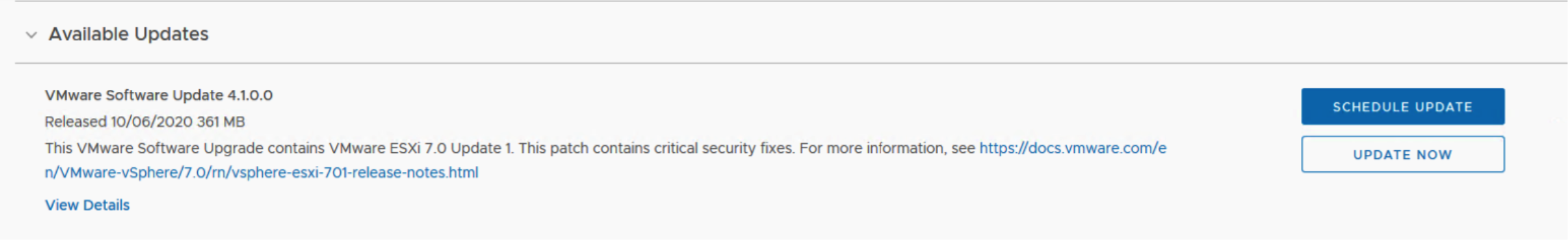
By default, all clusters can be selected in applicable domain, or individual clusters can be selected as per below screenshot

By default, all clusters are upgraded in parallel. To upgrade clusters sequentially, select Enable sequential cluster upgrade.


Click Enable Quick Boot if desired. Quick Boot for ESXi hosts is an option that allows Update Manager to reduce the upgrade time by skipping the physical reboot of the host. More details on Quick boot can be found on KB https://kb.vmware.com/s/article/52477
Once the ESXi upgrade task is initiated it can be monitored from SDDC Manager Tasks

As per normal, subtasks can be monitored by selecting the main task

Tasks can also be monitored from Workload domains Update tab

Click View Status for details
View status will give a granular view of the upgrade process.

Update Activity can be further interrogated by clicking View Update Activity

As each ESXi Node gets upgraded the status will be reflected on update activity.

Once upgrade completes the task will be marked successful on SDDC Manager

Summary
An admin should be able download bundles , configure and execute an upgrade of VCF including all managed infrastructure components
Appendix A - NSX-T Fabric Overview
NSX Configuration Overview: Management Workload Domain
NSX provides the core networking infrastructure in the software-defined data center stack within VCF. Every workload domain is integrated with and backed by an NSX-T platform.
For more information on NSX-T please review https://docs.vmware.com/en/VMware-NSX-T-Data-Center/index.html
The Management workload domain is preconfigured with NSX-T, For VI workload domains, NSX-T can be deployed alongside new workload domains or new workload domains can be added to existing NSX-T deployments. By default, workload domains do not include any NSX-T Edge clusters and as such are isolated.
During the initial VCF bring-up process, NSX-T is automatically deployed and configured in the management workload domain. Its default components include NSX-T 3.0 instance which is comprised of three controllers with a VIP for management access. Follow the steps below to review the main components of the NSX-T architecture and how it relates to VCF 4.X
- Log into SDDC Manager
- In the left panel, navigate to Inventory > Workload Domains
- Select the workload domain that is of type ‘MANAGEMENT’ (‘ mgmt-domain’ in this example):

Select the management cluster, (‘mgmt01’ in this example):

We can see that there is an NSX-T instance (nsx-mgmt-vcf.ssdc.lab) deployed with an associated NSX-T Edge Cluster (mgmt- edge-cluster), as we have chosen to deploy VCF with the option of AVN (Application Virtual Networks).
Note: If AVN was not chosen as part of bring-up, an Edge Cluster would not be available. as per the following screenshot:

Accessing NSX-T interface from SDDC Manager
Click on the hyperlink to launch NSX-T Web interface, and login with administrative privileges defined on bring-up i.e., admin
Once logged in from the NSX-T Dashboard we are shown four main dashboards Networking, Security, Inventory and System.

In the next section we will focus on System and Networking and how that relates to VCF.
NSX-T Appliances.
The NSX-T Data Center Unified Appliance is an appliance included in the installation of NSX-T. It includes the ability to deploy the appliance in the roles of NSX Manager, Policy Manager, or Cloud Service Manager.
VMware has combined both the NSX Manager and NSX controller into a single virtual appliance called “NSX unified appliance” which can be run in a clustered configuration.
During initial VCF 4.X bringup NSX-T Appliances are deployed on the management cluster and automatically configured as per the bring-up spec
This is the screen-shot of the VCF 4.X Excel spread-sheet section relating to NSX-T

To inspect the NSX-T appliances and cluster status
- Click on System to review the Fabric.
- On the left-hand navigation pane click on Appliances
We will first inspect the NSX-T Appliances. There are three appliances that are deployed and clustered together. To access the cluster a Virtual IP (in our case IP 10.0.0.20) to automatically configured as per VCF 4.0 bring up spec.
The NSX-T Cluster Status should be of status stable

Transport Zones
In NSX-T Data Center, a transport zone (TZ) is a logical construct that controls which hosts a logical switch can reach. A transport zone defines a collection of hosts that can communicate with each other across a physical network infrastructure. This communication happens over one or more interfaces defined as Tunnel Endpoints (TEPs).
There are two types of transport zones: Overlay and VLAN. An overlay transport zone is used by ESXi host transport nodes and NSX-T Edge Nodes. When an ESXi host or NSX-T Edge transport node is added to an Overlay transport zone, an N-VDS is installed on the ESXi host or NSX Edge Node.
VCF 4.x will automatically configure three transport zones (two if no AVNs are specified)
To inspect the transport zones automatically configured by VCF, click on Fabric > Transport Zones

We have three configured transport zones. The VLAN transport zone is used by NSX-T Edge Nodes and ESXi host transport nodes for its VLAN uplinks. When an NSX-T Edge Node is added to a VLAN transport zone, a VLAN N-VDS is installed on the NSX-T Edge Node.
- Overlay transport zone for host transport nodes and edge nodes
- VLAN-backed transport zone for host management networks, e.g., vSAN and VMotion VLAN-backed edge transport zone for Edge uplinks
To inspect host transport zone overlay
Click on transport zone name, in our example, mgmt-domain-tz-overlay01. The overview will show number of hosts and edges associated, number of switches and switch ports.
Click on Monitor to review the health and status of the transport nodes, in this case hosts and edge appliances

You may repeat this procedure for the remaining transport nodes.
Host Transport Nodes
In NSX-T Data Center, a Transport Node allows nodes to exchange traffic for virtual networks.
The vSphere hosts were defined on the VCF 4.X Excel Spread-sheet and act as Transport Nodes for NSX-T

To inspect the host transport nodes from an NSX-T perspective
- From the system view Click on Fabric -> Nodes
- From Host Transport Nodes click on drop down pick list next to "Managed by"
- Select the Compute Manager, in our case vcenter-mgmt.vcf.sddc.lab
- Expand the Cluster, in our case mgmt-cluster
We should now see (since this is a management cluster) a minimum of four vSphere hosts from the management cluster prepared successfully and Node status should be Up

The hosts were defined on the VCF 4.x Excel Spread-sheet as esxi-1 through to esxi-4
Edge Transport Nodes
The NSX Edge provides routing services and connectivity to networks that are external to the NSX-T Data Center deployment. An NSX Edge is required if you want to deploy a tier-0 router or a tier-1 router with stateful services such as network address translation (NAT), VPN and so on.
An NSX Edge can belong to one overlay transport zone and multiple VLAN transport zones. If a Virtual Machine requires access to the outside world, the NSX Edge must belong to the same transport zone that the VM's logical switch belongs to. Generally, the NSX Edge belongs to at least one VLAN transport zone to provide the uplink access.
We defined NSX-T Edges in the VCF 4.X Excel spread-sheet

To review the edge transport nodes and clusters.
Click on Fabric > Nodes > Edge Transport Nodes

Click on one of the edge-transport nodes for more details
We can see this edge is associated with 2 transport zones; a VLAN sfo01-m01-edge-uplink-tz and a host overlay transport zone mgmt-domain-tx-overlay01
Click on Monitor to review the system resources and how each interface on the appliance is associated to each uplink. the interfaces fp-ethX can be mapped to the virtual vNIC interfaces on the edge appliance.

Compute Manager
A compute manager, such as vCenter Server manages resources such as hosts and VMs.
NSX-T Data Center is decoupled from vCenter. When VCF bringup process adds a vCenter Server compute manager to NSX-T, it will use the vCenter Server user's credentials defined in the VCF 4.X bringup specifications.When registered NSX-T polls compute managers to find out about changes such as, the addition or removal of hosts or VMs and updates its inventory accordingly.
To inspect the configuration Click Fabric > Compute Managers

Click on the registered Compute Manager to gather more details, in this case it is the management vCenter server

NSX-T Logical Networking Overview
In this section we will review the logical networking concepts and how they relate to VCF 4.x Management Domain bring-up. A few terms to help with this overview, for more information please review the NSX-T 3.0 installation guide https://docs.vmware.com/en/VMware-NSX-T-Data-Center/3.0/installation/GUID-A1BBC650-CCE3-4AC3-A774-92B195183492.html
Tier-0 Gateway or Tier-0 Logical Router
The Tier-0 Gateway in the Networking tab interfaces with the physical network. The Tier-0 gateway runs BGP and peers with physical routers.
Tier-1 Gateway or Tier-1 Logical Router
The Tier-1 Gateway in the Networking tab connects to one Tier-0 gateway for northbound connectivity and one or more overlay networks for southbound connectivity.

Segment
This is also known as a logical switch. A segment provides virtual Layer 2 switching for Virtual Machine interfaces and
Gateway interfaces. A segment is a logical entity independent of the physical hypervisor infrastructure and spans many hypervisors, connecting VMs regardless of their physical location.
Virtual machines attached to the same segments can communicate with each other across transport nodes through
encapsulation over tunneling.
When segments are created, they appear as a port group on vSphere.
Tier-0 and Tier-1 Gateways
To review the Tier-0 Gateway deployment
From the main NSX-T Dashboard, click on Networking > Tier-0 Gateways. We can see that the Tier-0 gateway, mgmt-edge- cluster-t0-gw01, has been deployed as part of VCF 4.x bring-up.

Click on Linked -Tier1 Gateways. we now see that the Tier-1 Gateway, mgmt-edge-cluster-t1-gw01 is associated with the Tier-0 gateway

Click on Networking > Tier-1 Gateways

Click on Linked Segments, we see the Tier-1 Gateway is associated with 2 segments. These segments were defined on the VCF bring-up spec

Tier-0 BGP Routing
To enable access between your VMs and the outside world, you can configure an external or internal BGP (eBGP or iBGP) connection between a tier-0 gateway and a router in your physical infrastructure.

This is a general review of BGP routing and how it was defined on the VCF 4.X bring-up and what it looks like on the NSX-T Manager
Here are the deployment parameters for the AVNs on VCF 4.x spreadsheet. This part of the bring-up simply defined how the Edges for the management cluster would be deployed and what should the configuration of Tier-0 (with BGP) and Tier-1 gateways looks like.

Note the following details,
- Edge Autonomous System ID 65003
- Top of Rack Autonomous System ID 65001
- Top of Rack IPs 192.168.16.10 and 192.168.17.10
When configuring BGP, you must configure a local Autonomous System (AS) number for the Tier-0 gateway. VCF spec set this value to 65003. Both edges must use the same AS number
You must also configure the remote AS number on the Top of Rack switches. As per the VCF bringup spec, the physical Top of Rack switch AS number is 65001.
EBGP neighbors must be directly connected and in the same subnet as the tier-0 uplink.
We can see by the VCF screenshot above both edge node 1 and edge node 2 have Uplinks defined on 192.168.16.0/24 and 192.168.17.0/24.
We also see both top of rack switches have IP addresses on the same subnet i.e., 192.168.16.10 and 192.168.17.10
From the main NSX-T Dashboard, click on Networking > Tier-0 Gateways.
Expand the Tier-0 Gateway for more details.
Expand BGP Details.
We can see the local AS number is 65003 which matches the excel spreadsheet entry.

Next, we will look at the BGP Neighbors. we can see the detail by looking at the details behind the BGP Neighbors, in this case 2
Now we see that there are two neighbors configured, 192.168.16.10 and 192.168.17.10, with AS number 65001 this matches the Top of Rack Switch details defined on the VCF spreadsheet.

For a graphical representation of Tier-0 BGP configuration, close the BGP Neighbors detail and click on topology view highlighted below in red. We can see the IP addresses 192.168.16.2, 192.168.16.3, 192.168.17.2 and 192.168.17.3 are configured and peered to the Top Of rack Switches (192.168.16.10 and 192.168.17.10)


Segments
This is also known as a logical switch. as per the VCF 4.0 Bring up spec, we have defined two segments as per the AVN setup for Virtual Machine Traffic.
These are Region -A Logical Segment called local-sgement and xRegion Logical Segment xregion-segment

To view the AVN Segments, click on Networking > Segments.
Take note of the two segments highlighted below, these are backed by management domain overlay transport zone.

These Segments are presented as Port Groups on vSphere.
To view on vSphere
- Login to vSphere Management vCenter server,
- Navigate from Home > Networking > Management Networks
- expand management distributed switch and locate the segments

The remaining two Segments are for VLAN backed up-link connectivity for the NSX-Edges
These VLANs were defined on bring-up on the VCF 4.X excel spreadsheet, see NSX-T Edge Uplink-1 and Edge-Uplink-2

This is a detailed view of one of the NSX-T Edge uplink segments (Edge Uplink 1)

NSX-T Edge Overlay
An NSX-T Edge overlay is also defined for on VCF 4.X bring up excel spreadsheet

Separate VLANs and subnets are required for NSX-T Host Overlay (Host TEP) VLAN and NSX-T Edge Overlay (Edge TEP) VLAN, as it is a form of isolating the traffic for each onto a separate VLAN.
In this way we use separate VLANs for each cluster for the Host TEPs - so if you had three clusters you could have three separate Host TEP VLANs and one Edge TEP VLAN.
By separating the traffic onto different VLANs and subnets we remove a potential SPOF. e.g., if there was a Broadcast Storm in the Host TEP VLAN for one cluster it wouldn’t impact the other clusters or Edge Cluster.
NSX-T Host Overlay (Host TEP) VLAN and NSX-T Edge Overlay (Edge TEP) VLAN must be routed to each other. so, in our case the NSX-T Host Overlay VLAN 0 is routed to NSX-T Edge Overlay VLAN 1252.
You cannot use DHCP for the NSX-T Edge Overlay (Edge TEP) VLAN.
Note: The NSX Manager interface provides two modes for configuring resources: Policy and Manager View. For more information read the NSX-T 3.0 documentation https://docs.vmware.com/en/VMware-NSX-T-Data-Center/3.0/administration/GUID-BB26CDC8-2A90-4C7E-9331-643D13FEEC4A.html#GUID-BB26CDC8-2A90-4C7E-9331-643D13FEEC4A

To review the NSX-T Overlay configuration you may have to switch to Manager View. Click on Manager on the top right of the NSX-T Main menu if not already in Manager mode.

Now click on Logical Switches on Networking Dashboard
Click on Edge Overlay name as defined on the VCF 4.0 excel spreadsheet, in this case sddc-edge-overlay
The summary shows this logical switch is associated with the overlay transport zone mgmt-domain-tz-overlay01

Click on Transport Zone to view the transport zone and "Where Used"

To review where the VLAN 1252 is defined, click on System > Fabric > Nodes > Edge Transport nodes.
Select an edge node and select edit. the Edge node is associated with two transport zones, and a profile that defines VLAN 1252

Click on System > Fabric > Profiles
An uplink profile defines policies for the links from hosts to NSX-T Data Centre logical switches or from NSX Edge nodes to top-of- rack switches.
The settings defined by uplink profiles include teaming policies, active/standby links, the transport VLAN ID, and the MTU setting in our case uplink-profile-1252 has the teaming and VLAN settings defined on the uplink profile associated with the Edge transport nodes
