
vSAN Availability Technologies
Overview
Introduction
Maintaining access to application services and data continues to be the top priority for nearly all IT organizations. Service level requirements from lines of business are higher than ever before. Loss of access to applications and data often causes losses in productivity and revenue. As a result, systems such as servers, the network, and storage are commonly architected to provide the highest levels of uptime. Many consider storage the foundational component of an IT infrastructure. SAN and NAS solutions have been the traditional choices for highly available, shared storage services.
The future of modern infrastructure is hyper-converged infrastructure (HCI). It offers a common operational model for computing, storage, networking, and even cloud resources from a single console. The modern HCI software stack runs on standard x86 server hardware with local storage devices. These storage devices are pooled and presented to servers as a shared datastore. VMware vSAN is a common example of this approach. HCI can be deployed in primary data centers, remote office locations, and the public cloud.
As with any enterprise-class storage solution, maintaining access to applications and data is paramount. HCI powered by vSAN is no exception. This document provides technical coverage of how vSAN works to provide the highest levels of availability and durability.
Much of the content in this document assumes the use of the Original Storage Architecture (OSA) found in all versions of vSAN. The characteristics of the Express Storage Architecture (ESA) are not fully documented here, but shares many similarities.
vSAN Architecture Basics
HCI powered by vSAN takes a "scale-out storage" or "storage clustering" approach. In other words, persistent storage devices and the data they contain are distributed across the entire cluster of hosts. This is significantly different from a traditional storage approach where a single cabinet contains the storage controllers, drives, and networking connections. The loss of a few components in a traditional storage array or, worse yet, loss of the entire cabinet means all of the datastores in this cabinet are impacted. Spreading I/O and data across several drives connected to multiple storage controllers in a cluster of hosts limits the impact of a failure to that device or host. Data stored on vSAN is redundant and distributed across the cluster on multiple vSAN hosts. Therefore, the data is still accessible even if a host is offline.
vSAN requires a minimum of three hosts in a cluster. vSAN can scale up to 64 hosts in a cluster and VMware vCenter Server can manage multiple clusters. However, more common cluster sizes range from eight to 12 hosts. There are many recommendations and design decisions that must be made based on the requirements of the business. The document titled vSAN Cluster Design - Large Clusters Versus Small Clusters provides excellent guidance on the topic of cluster size.
vSAN Express Storage Architecture (ESA)
vSAN Express Storage Architecture in vSAN 8 is a single-tier architecture optimized for high performance NVMe based TLC flash devices for both on-premises environments, and for the hyperscale public clouds. Each host has a disk pool of these devices. There is one vSAN datastore per cluster. All hosts in the cluster have access to this shared datastore, which enables core vSphere availability features such as VMware vSphere vMotion, vSphere DRS, and vSphere HA.
vSAN Original Storage Architecture (OSA)
The follow section covers the vSAN original storage architecture design.
Figure 1 below shows a cluster with four hosts. Each of these hosts contains two disk groups. The drives in a vSAN disk group are dedicated to vSAN use. A vSAN host with one disk group is supported, but a common design recommendation calls for at least two disk groups. This can be scaled up to five disk groups.
Each disk group contains one cache drive, which must be a flash-based storage device. All of the cache devices across the disk groups in every host is referred to as the cache tier. A disk group must also contain at least one capacity drive. A maximum of seven capacity drives per disk group is supported. The capacity drives across the cluster are collectively called the capacity tier. Capacity drives can be magnetic disks or flash-based devices.
Clusters with flash devices in the cache tier and magnetic devices in the capacity tier are called hybrid clusters. Clusters with flash devices in both tiers are referred to as all-flash clusters. Mixing hybrid and all-flash configurations within the same vSAN cluster is not supported.
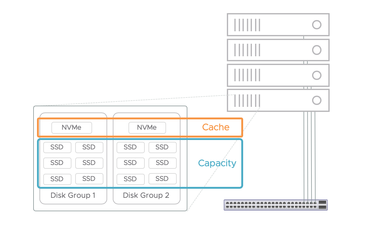
Figure 1. A 4-node vSAN cluster with two disk groups per host.
vSAN OSA utilizes a 2-tier architecture by design. The cache tier does not contribute to the overall capacity of a vSAN datastore. It is used exclusively for read-caching and/or write-buffering depending on whether the configuration is hybrid or all-flash. The capacity drives collectively determine the raw size of the vSAN datastore. There is one vSAN datastore per cluster. All hosts in the cluster have access to this shared datastore, which enables core vSphere availability features such as VMware vSphere vMotion, vSphere DRS, and vSphere HA.
vSAN Objects and Components
Objects and Components
An overview of vSAN's objects and components can be found on the following blog post: vSAN Objects and Components Revisited. For more information on Object and component behaviors see the VSAN Design Guide.
vSAN ESA Snapshots - Snapshots will no longer be split out as their own discrete objects and components.
The following information is specific to the vSAN Original Storage Architecture.
vSAN is an object datastore with a mostly flat hierarchy of objects and containers (folders). Items that make up a virtual machine are represented by objects. The various types of objects that exist include virtual disks (VMDK) and VM Home namespace. Each object consists of one or more components. The maximum size of a component is 255GB. If an object is larger than 255GB, it is split up into multiple components. Figure 3 below shows a 600GB virtual disk split into 3 components.
Storage Policies and Component Placement
Storage Policy Based Management
The number of components that make up an object is also determined by the type and level of availability rules that are applied as part of a storage policy.
Storage Policy Based Management (SPBM) is the management framework utilized to govern storage services applied to objects on vSAN and Virtual Volumes (VVols ). A storage policy consists of one or more rules that determine items such as the level of availability, performance, capacity consumption, etc. Storage policies are created and managed using the vSphere Client (HTML5 or FLEX). Policies can be assigned to virtual machines and individual objects such as a virtual disk.
Storage policies are easily changed or reassigned if application requirements change. These modifications are performed with no downtime and without the need to migrate virtual machines from one datastore to another. SPBM makes it possible to assign and modify service levels with precision on a per-virtual machine basis.
Figure 4 shows the VM Storage Policy wizard. The availability tab provides options for “Site disaster tolerance” where you can choose from various standard and stretched cluster configurations, and “Failures to tolerate” where you can choose the number of failures to tolerate and the failure tolerance method (RAID-1, RAID-5\6).

Protection Against a Storage Device or Host Failure
The most common question asked when discussing vSAN availability is how does vSAN protect against a storage device or host failure. The most common method is by mirroring objects across multiple hosts. For example, if we configure a storage policy to contain a rule that maintains availability in the event of a storage device or host failure, vSAN will create two replicas of an object and place them on separate hosts. If one of the hosts or storage device(s) contained in a host fails, the object is still accessible using the replica on the other host. In other words, we can tolerate the failure of one host and still maintain access to the data. The simple formula: Data availability after N fault domain failures requires N+1 replicas. The data on each host in Figure 5 is a mirror copy.

The storage policy rule that determines the level of availability of an object on vSAN is Primary level of Failures to Tolerate or PFTT. If PFTT=1, we are instructing vSAN to create and place replicas of the object so that the failure of a storage device or host can be tolerated.
There is also a rule named Failure Tolerance Method, which contains two options: RAID-1 mirroring and RAID-5/6 erasure coding. RAID-1 mirroring with PFTT=1 are the default settings for vSAN. We will discuss RAID-5/6 erasure coding shortly.
Witness Components
As with many clustering solutions, having an even number of replicas creates the risk of a "split brain" scenario when the hosts containing the replicas are unable to communicate with each other over the network. To solve this issue, vSAN will typically create another component called a "witness." This witness component is small - approximately 4MB - and serves as a tie-breaker when a partition occurs as shown in Figure 6.

For an object to be accessible, vSAN must achieve a quorum for the object by having access to more than 50% of the active components that make up an object. In the example above, a minimum of both data components or a data component and the witness component must be accessible to have a quorum. If any two of the three components above (or all three) are offline, the object would not be accessible until greater than 50% are back online.
It is important to note that witness components might not be utilized in all cases. Recent versions of vSAN utilize the concept of "votes." More than 50% of the votes must be available to achieve quorum. Each component usually has a vote count equal to 1. In some cases, if the number of replicas (each with 1 vote) is even, vSAN will simply add a vote to one of the components making the number of votes odd. Quorum is achieved if more than 50% of the votes are accessible.
RAID-5/6 Erasure Coding
RAID 5/6 with vSAN ESA
vSAN Express Storage Architecture has an innovative new parity raid system. For more information see this document.
RAID 5/6 with vSAN Original Storage Architecture
The other failure tolerance method is RAID-5/6 erasure coding. Selecting this option for the Failure Tolerance Method rule enables PFTT=1 and PFTT=2 resilience while reducing the amount of raw capacity consumed when compared to RAID-1 mirroring.
For example, a 100GB object protected by RAID-1 mirroring and PFTT=1 consumes 200GB, i.e., 2 x 100GB replicas. That same 100GB object protected by RAID-5 erasure coding (FTT=1) consumes 133GB of raw storage - a 33% reduction versus RAID-1 mirroring. The following diagram shows component placement in a 4-node all-flash vSAN cluster for an object protected by RAID-5 erasure coding.

Note there are three data components plus a parity component. At least three of the four components must be present for this object to be accessible. in other words, we can tolerate the loss of any one host and maintain accessibility, i.e., PFTT=1. If PFTT is set to 2 and RAID-5/6 erasure coding is selected as the failure tolerance method, we would see six components distributed across six hosts - four data components and two parity components. RAID-6 erasure coding (PFTT=2) reduces raw capacity consumption by 50% versus PFTT=2 with RAID-1 mirroring.
While RAID-5/6 erasure coding does help conserve capacity, there are tradeoffs. More hosts are required to satisfy PFTT=1 and PFTT=2 RAID-5/6. As shown in the example above a minimum of three hosts are required for RAID-1 mirroring while RAID-5 erasure coding requires at least four hosts. Erasure coding also introduces write amplification as parity components must also be updated when data components are written to. This failure tolerance method has the potential to impact performance, and this is the case with any type of storage (not just vSAN). Since vSAN requires the use of all flash devices to support RAID-5/6 erasure coding, little if any performance impact is observed. For a deeper dive on how vSAN utilizes RAID-5/6 erasure coding, read this blog
https://blogs.vmware.com/virtualblocks/2018/06/07/the-use-of-erasure-coding-in-vsan/
Data Placement Scheme Recommendations
vSAN Express Storage Architecture RAID Recommendations
RAID 5/6 should always be chosen over RAID 1, with rare exceptions such as 2 node where it is not possible. For more information about the new adaptive raid policies see the vSAN Design Guide or this document that compares the new RAID 5/6 policies.
vSAN Original Storage Architecture (OSA) RAID Recommendations
RAID-1 mirroring should be used if performance is most important and you have plenty of raw capacity. RAID-1 mirroring is your only option if you are using a hybrid vSAN configuration. If you have an all-flash vSAN configuration and space efficiency is more important, RAID-5/6 erasure coding reduces capacity consumption with very little or no impact on performance.
Note: It is important to remember that it is possible to assign a different policy to each object.
Consider a VM running a database - it might make sense to have a RAID-1 policy assigned to some VMDKs and a RAID-5/6 policy assigned the other VMDKs. This is an excellent example showing one of the many benefits of SPBM and vSAN.

Note : In vSAN 6.7, the behavior of VM swap objects now inherits the storage policy assigned to the VM home space object. Different workloads can now be easily assigned storage policies that are appropriate for their VM swap object.
Network Partition Groups
vSAN Utilizes the Network
vSAN consists of two or more physical hosts typically connected by a 25Gbps networking. 25Gbps or faster is recommended and explicitly required for vSAN express Storage Architecture. 10GbE is required for vSAN Original Storage Architecture. These network connections are required to replicate data across hosts for redundancy and to share metadata updates such as the location of an object's components.
As with any storage fabric, redundant connections are strongly recommended. The VMware vSAN Network Design Guide provides more details on network configurations and recommendations. Due to vSAN’s dependence on the network, many questions arise concerning network connectivity between hosts in the cluster. This section aims to address such questions.
Every host in the cluster must have a vmkernel adapter with the vSAN service enabled, as shown in the screenshot below.

The vSAN heath check service verifies a vmkernel adapter with the vSAN traffic service enabled is present on each host. The health check service also verifies many other network configurations and connectivity, as shown in figure 10.

Network Partition Groups
A module of vSAN called the Cluster Monitoring, Membership, and Directory Services (CMMDS) is responsible for monitoring links to the cluster. A leader node (host) and a backup node are elected in a vSAN cluster. The leader node is responsible for dispatching an update provided by one node to all other nodes in the cluster. In a healthy cluster where all nodes are communicating over the vSAN network, there is only one leader node and a backup node. All the nodes in this healthy cluster are members of the same network partition group. Nor
mally, there is only one network partition group named "Group 1" as seen in this screenshot.

If both the leader and the backup nodes go offline, the CMMDS participates in electing a new leader node and backup node. In the case where one or more hosts become isolated from each other, vSAN will attempt to form a vSAN cluster and elect a leader in each partition. In other words, it is possible to have more than one network partition group.

vSAN and vSphere High Availability (HA) Integration
vSphere HA uses the same network connections as vSAN when vSAN is enabled. This helps ensure that vSphere HA and vSAN see the same network partition(s) in a cluster. Having a consistent view of network partitions across vSAN and HA enable accurate and reliable responses to host isolation and multiple network partitions.
For many years, VMware vSphere and vSAN have provided users the ability to maintain high availability of an application in the event of an unexpected outage. “vSphere HA” is a cluster feature that is reactive: taking action to make an application available again. vSphere Proactive HA, first introduced with vSphere 6.5 is proactive: taking action to remove applications off of hosts suspected of imminent failure. vSAN 7 U2 now supports vSphere Proactive HA, where the application state and any potential data stored can be proactively migrated to another host. This is yet another great addition to making sure applications are running at their highest levels of availability.
There are a number of recommendations to consider when configuring vSphere HA for a vSAN cluster. For detailed information on network design and sizing please refer to the vSAN Design Guide.
Single Host is Isolated
An object is available if >50% of its components (more specifically, votes) are active and accessible. There are a minimum of three components when Primary Number of Failures to Tolerate (PFTT) = 1. There are two replicas, which contain mirror copies of the data, and a witness, which acts as a tie breaker when the network is partitioned.
As we saw in Figure 12 above, a second network partition group (Group 2) is created when a host becomes isolated from the rest of the cluster. Components are distributed across hosts for availability. In the case of PFTT=1 and RAID-1 mirroring, a minimum of three components are present. Each one resides on a different host. That means the isolated host has access to, at most, one of the three components that make up an object.

There is no way for this host by itself to achieve a quorum for any of the objects. A VM can run on the isolated host, but it will not be able to read or write to storage as it does not have access to its objects (VM Home, VMDKs, etc.).
To resolve this issue, vSphere HA powers off running VMs on the isolated host and attempts to restart them on other hosts in the cluster. These other hosts in network partition Group 1 have access to enough components (more than 50%) to enable access to the objects. The VMs are restarted successfully even though one of the hosts are offline.
Net result: No data loss and downtime for the VMs on the affected host is minimized.
This video demonstrates the rapid recovery of 50 VMs affected by a host failure.
All Hosts are Disconnected
A loss of network connectivity between all the hosts in a vSAN cluster is more serious. Each host in the cluster effectively forms its own single-node cluster. In other words, there are multiple network partition groups. This screenshot shows four network partition groups as the vSAN network on all hosts in this 4-node cluster is disconnected.

Each host still has access to the data on its local drives. The challenge in this scenario is components are commonly distributed across multiple hosts. Therefore, it is not possible for any of the disconnected hosts to have access to greater than 50% of the components. Even if one of the components that make up a VM's object is located on the same host where the VM is running, that is still access to less than 50%. In other words, any VMs where PFTT=1 or higher will not be able to read and write to any of its objects.
The VMs might continue to run from a compute and memory standpoint, but they will not be able to write to storage. VMs in this state are sometimes referred to as "zombie" VMs and they often end up crashing.
The good news is data is not lost and access to objects will be restored when network connectivity is restored. Any "zombie" VMs might have to be reset to resume normal operations.
A corner-case scenario when a VM might be able to survive the disconnection of all hosts is when a VM has a policy assigned with PFTT=0. The component(s) that make up the object could be located on the same host where the VM is running. However, it is more likely components will be located on other hosts - even in a small, 3-node cluster. This likelihood increases as the number of hosts in the cluster increase. Therefore, assigning a policy with PFTT=0 is not an effective measure to counteract the effects if multiple host disconnections.
Network Recommendations
These are the vSAN Network recommendations applicable to vSAN availability:
1. Design your vSAN network to be resilient just like any other storage fabric.
2. Consult the VMware vSAN Network Design Guide .
3. Read the Using vSphere HA with vSAN documentation.
vSAN Component States
vSAN Component States
vSAN components can be found in a few different states:
- Active
- Reconfiguring
- Absent
- Degraded
- Stale
Active Components
The most common state is Active , which means the component is accessible and is up to date. Below we see two components that are Active .

Reconfiguring Components
Another common component state is Reconfiguring . This state is observed when a change to a storage policy is made, a new storage policy is assigned to an object, host maintenance mode, or loss of a storage device, controller or entire host. The screenshot below shows a component in the Reconfiguring state.
![]()
If an issue occurs that takes a storage device or entire host offline, components on the device are marked as Absent or Degraded depending on the issue.
Absent Components
As you would expect, losing access to a component typically reduces the availability level of an object. Consider this example: A 100GB VMDK object with a storage policy assigned where the Failure Tolerance Method is RAID-1 mirroring and PFTT=1. vSAN creates two mirrored copies (replicas) each on separate hosts. A witness object is placed on a third host in the cluster. A host containing one of these objects goes offline. Two of the three components are still active, which means the object is still accessible. However, if a second host containing another one of those objects goes offline, the object would be inaccessible.
vSAN, like many other storage solutions, will perform rebuilds to restore the appropriate level of resiliency. This operation on any storage platform is expensive in terms of I/O - especially if large amounts of data must be copied. vSAN attempts to make an "educated guess" on whether components will become available again in a reasonable amount of time. If components will be available again shortly - after a host reboot, for example - it does not make sense to start a (costly) rebuild process.
If a component goes offline without additional information, vSAN expects the component will come back online shortly. This situation is often referred to as All Paths Down (APD). vSAN will mark missing components in this scenario as Absent .
![]()
vSAN 7 Update 1 introduces a new system for planned maintenance. A object will be created that absorbs the missing writes from the absence components. In the event of a additional loss, if the absent component is restored by removing the host from maintenance mode, availability of an other unavailable object may be restored. For more information, see this section of the vSAN Design Guide.
Examples of this nature include host reboots, network partitions, and pulling a storage device from a server chassis. vSAN will wait 60 minutes by default before starting the rebuild process for components marked as Absent . The goal of this approach is to avoid unnecessary rebuilds. The 60-minute rebuild timer can be changed. This VMware KB article discusses the process.
Recommendation : Avoid changing the default rebuild timer setting of 60 minutes as this provides a good balance of avoiding unnecessary rebuilds while minimizing the risk of downtime. If a situation occurs where a timelier rebuild is desired, it is possible to trigger a rebuild using the Repair Objects Immediately in the vSAN Health Check user interface.
Degraded Components
A component that is marked as Degraded occurs when a storage device fails, and error codes are sensed. vSAN assumes a defective device will not come back online and the rebuild process is started immediately. This scenario is commonly referred to as a Permanent Device Loss (PDL).
As a side note simply pulling a storage device is not an accurate way to simulate a storage device failure when performing a proof of concept. vSAN sees this as an APD situation and expects the device will come back online shortly. Therefore, vSAN will wait 60 minutes (default) before starting the rebuild process. This led several administrators to believe that vSAN was not working properly when in fact it was working as designed.
Stale Components
The last component state discussed in this document is Active-Stale , as shown in the following screenshot.

vSAN use sequence numbers to verify a component has the latest updates. This sequence number is normally kept consistent across components that make up an object. When a change to the object occurs, the data is written to both replicas, for example, and the sequence number is updated for the components. If a component is active, but its sequence number is different/older than the current sequence number for the object, the component is marked as Active - Stale. This usually occurs when the components of an object go offline and come back online concurrently at different times.
To help clarify this, consider Figure 18 above. The storage policy assigned to the object was RAID-1 mirroring and PFTT=1. Host 02 went offline first. The object was still available as vSAN was able to achieve a quorum with the replica on Host 04 and the witness on Host 01. Updates to the components on Host 04 and Host 01 continued to occur while Host 02 was offline. Then, Host 04 also went offline.
At this point two of the three components were offline, so the object became inaccessible. Host 02 eventually comes back online, and the component becomes Active . However, the sequence number of the component on Host 02 is outdated and Host 04 is still offline. In other words, the component on Host 02 is missing the most recent changes and vSAN is "aware" of this due to the difference in sequence numbers. Even though two of the three components that make up the object are active, vSAN keeps the object inaccessible to avoid data loss or corruption. The object will remain inaccessible until the object on Host 04 is online with the most recent data. vSAN will then synchronize the stale component with the component that contains the latest data and enables access to the object.
vSAN Component Intelligent Rebuild
vSAN achieves high availability and extreme performance through the distribution of data across multiple hosts in a cluster. Data is transmitted between hosts using the vSAN network. There are cases where a significant amount of data must be copied across the vSAN network. One example is when you change the fault tolerance method in a storage policy from RAID-1 mirroring to RAID-5 erasure coding. vSAN copies or “resynchronizes” the mirrored components to a new set of striped components.
Another example is repair operations such as when vSAN components are offline due to a host hardware issue. These components are marked “absent” and colored orange in the vSAN user interface. vSAN waits 60 minutes by default before starting the repair operation. vSAN has this delay as many issues are transient. In other words, vSAN expects absent components to be back online in a reasonable amount of time and we want to avoid copying large quantities of data unless it is necessary. An example is a host being temporarily offline due to an unplanned reboot.
vSAN will begin the repair process for absent components after 60 minutes to restore redundancy. For example, an object such as a virtual disk (VMDK file) protected by a RAID-1 mirroring storage policy will create a second mirror copy from the healthy copy. This process can take a considerable amount of time depending on how much data must be copied. The rebuild process continues even if the absent copy comes back online in versions of vSAN prior to 6.6.

The object repair process improved starting in vSAN 6.6 with Intelligent Rebuilds. A high-level description is included here, with pointers to more details.
If absent components come back online while vSAN is rebuilding another copy, vSAN will determine whether it is more efficient to continue building an entirely new copy or update the existing copy that came back online using Smart Efficient Repairs . vSAN will restore redundancy using the most efficient method and cancel the other action. This enhancement in vSAN 6.6 rebuilds improves the speed and efficiency of object repair operations to reduce risk and minimize resource usage.
In cases where there are not enough resources online to comply with all storage policies, vSAN 6.6 will repair as many objects as possible, a Partial Repair . This helps ensure the highest possible levels of redundancy in environments affected by unplanned downtime. When additional resources come back online, vSAN will continue the repair process to comply with storage policies.
Enhanced Rebalancing is the act of redistributing components across the hosts that comprise a vSAN datastore. The need to rebalance can be for a number of different reasons, such as thin provisioned virtual disks being filled up, or introducing an additional host to vSAN, but the objective remains the same: Effective balancing of components across hosts leads to more efficient utilization of resources for both performance and capacity, and minimizes the effort to accommodate planned or unplanned events in a cluster.
Maintenance mode will, with vSAN 7 update 1 proactively redirect missing writes for otherwise absent components. For more information, see the vSAN Design Guide - Maintenance considerations.
Rebalancing efforts fall into two general categories: Proactive rebalancing, and reactive rebalancing.
Proactive rebalancing occurs when disks are less than 80% full. The opportunity to run a proactive rebalance will only occur when any single disk has consumed 30% more capacity than the disk with the lowest used capacity. vSAN automatically checks for these conditions and will provide a health check alert that will allow the user to invoke a rebalance using the "Proactive Rebalance Disks" button in the Health section of the vSAN UI.
Reactive rebalancing occurs when any disk is more than 80% full. This is an automatic process taken by vSAN to ensure the best distribution of components. An imbalance will automatically be detected, and vSAN will automatically invoke efforts to achieve better balance.
Adaptive Resynchronization
vSAN Express Storage Architecture Adaptive Re-synchronization
For vSAN ESA, adaptive resynchronization was moved to the networking stack as disk groups no longer exist.
vSAN Origional Storage Architecture Adaptive Re-synchronization
Excessive amounts of vSAN backend resynchronization traffic might affect cluster performance. Resynchronization operations in previous versions of vSAN are automated and controlled entirely by vSAN. In other words, administrators are unable to adjust the rate at which resynchronization operations are performed. Throughput of resynchronization operations could be manually adjusted to reduce the impact of excessive resynchronization activity at the cost of an increase in the amount of time needed to rebuild and or resynchronize components.
vSAN 6.7 introduces an Adaptive Resynchronization feature to ensure fair-share resources are available for virtual machine I/O and resynchronization I/O as the I/O changes.
When I/O activity exceeds the sustainable Disk Group bandwidth, Adaptive Resync guarantees bandwidth levels for VM I/O and resynchronization I/O. During times without contention, VM I/O or resynchronization I/O are allowed to use additional bandwidth. If there are no resynchronization operations being performed VM I/O can consume 100% of the available Disk Group bandwidth. During times of contention, resynchronization I/O will be guaranteed 20% of the total bandwidth the Disk Group is capable of. This allows for a more optimal use of resources.
Fault Domains
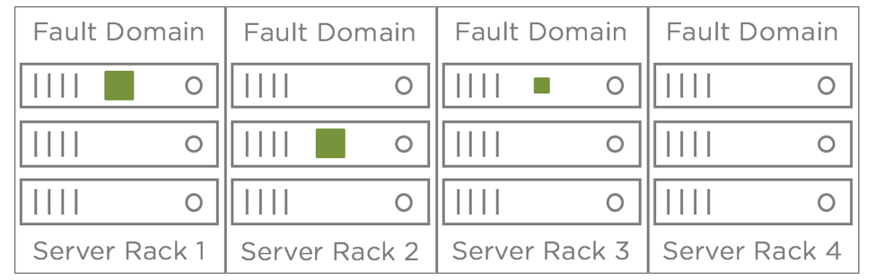
Fault domain is a term that comes up often when discussing availability. In IT, a fault domain usually refers to a group of servers, storage, and/or networking components that would be impacted collectively by an outage. A very common example of this is a server rack. If a top-of-rack (TOR) switch or the power distribution unit (PDU) for a server rack failed, it would take all of the servers in that rack offline even though the servers themselves are functioning properly. In this example, the server rack is considered a fault domain.
vSAN includes a feature called " Rack Awareness ," which enables an administrator to configure fault domains in the context of a vSAN cluster.
Host is Implicit Fault Domain
Each host in a vSAN cluster is an implicit fault domain. vSAN automatically distributes components of a vSAN object, e.g., virtual disk (VMDK), across hosts in a cluster based on the Number of Failures to Tolerate (FTT) rule assigned to that virtual machine (VM).
For example, a VM has the default setting of PFTT=1 - the object can withstand the failure of one storage device or host that contains a component and the object is still accessible. These objects are spread across multiple hosts to provide that resiliency. The following diagram shows this basic example. The larger green squares are data components and the smaller, green square is the witness component for this object. The two larger components are mirrored copies of the object and the smaller component represents the witness component.

Rack Awareness
While the failure of a storage device or entire host can be tolerated, what if these servers are in the same rack and the TOR switch goes offline? Answer: All hosts are isolated from each other and none of the objects are accessible as described earlier.
To mitigate this risk, the servers in a vSAN cluster should be spread across server racks and fault domains must be configured in the vSAN user interface. After fault domains are configured, vSAN will redistribute the components across server racks to eliminate the risk of a rack failure taking multiple objects offline. Figure 20 below shows what this might look like with a 12-node vSAN cluster spread across four server racks.
It is very simple to configure fault domains in vSAN. This short video demonstrates the process for configuring multiple vSAN Fault Domains. https://www.youtube.com/watch?v=X_xwo3SMaXY
Regardless of whether fault domains are configured or not, here are some numbers to keep in mind when designing a vSAN cluster:
RAID-1 mirroring requires 2N+1 fault domains, where N is the PFFT setting.
| Number of Failures to Tolerate | Minimal # of Fault Domains |
| FFT=1 | 3 |
| FFT=2 | 5 |
| FFT=3 | 7 |
RAID-5/6 erasure coding requires 2N+2 fault domains, where N is the FFT setting.
| Number of Failures to Tolerate | Minimal # of Fault Domains |
| FFT=1 | 4 |
| FFT=2 | 6 |
| PFFT=3 | Not supported |
If you attempt to assign a policy that requires more hosts than what is available, you will see an error message like this one:

Consider an Additional Host
Another scenario to consider is if there are enough fault domains for rebuilds when there is a host or storage device failure. Remember vSAN will either attempt to rebuild objects with reduced availability immediately or after 60 minutes. However, there must be enough fault domains to satisfy the availability rules in a storage policy.
Consider a 3-node cluster. If a host is offline, that leaves only two hosts. vSAN objects will still be available, but the cluster will not be able to tolerate another failure. Furthermore, vSAN is unable to rebuild components to restore redundancy while that host is offline. Adding a fourth host to the cluster enables the rebuild of components in cases where a storage device or host has failed or must be in maintenance mode for an extended period of time.
Recommendation : Add at least one more host for rebuilds. Example: RAID-1, PFTT=1, at least 4 hosts/fault domains.

Maintenance Mode
Planned Downtime
In addition to unplanned downtime, we need to discuss planned downtime. The primary example of planned downtime is host maintenance. There are many reasons a vSphere host might need to be taken offline such as firmware updates, storage device replacement, and software patches.
vSphere has a feature designed specifically for these types of activities called "maintenance mode." When a host is put into maintenance mode, vSphere automatically evacuates running virtual machines to other hosts in the cluster. This is done with vMotion so that virtual machine downtime is not incurred. This can take just a few minutes or several minutes depending on factors such as the number of virtual machines that must be migrated and vMotion network speed. Once all of the virtual machines have been evacuated, the host enters maintenance mode and maintenance on that host can begin.
vSAN introduces another consideration, which is the utilization of local storage devices inside of each host. These devices contain components that make up vSAN objects. Shutting down or rebooting a host makes these components inaccessible until the host is back online.
vSAN also accomodates for unplanned environmental conditions such as sudden power loss. While a good data center design should always provide for redundant or temporary power, a sudden loss in power will not compromise the integrity of the VMs or the data because all writes are persisted to non-volatile media.
Maintenance Mode with vSAN
When a host that is part of a vSAN cluster is put into maintenance mode, the administrator is given three options concerning the data (vSAN components) on the local storage devices of that host. The option selected has a bearing on a couple of factors: The level of availability maintained for the objects with components on the host and the amount of time it will take for the host to enter maintenance mode. The options are:
- Full data migration
- Ensure accessibility (default)
- No data evacuation
A maintenance mode pre-check is included to help ensure adequate capacity remains after a host is evacuated. This function is also used when removing a disk or disk group. Conducting this pre-check prior to evacuating a host provides a better understanding of how the cluster will be impacted from a capacity standpoint. Changes in storage policy compliance are also indicated.

The following diagrams are examples of component placement when using vSAN Maintenance Mode. Figure 24 shows a four-node cluster and only two objects to keep things simple. One object is assigned a storage policy with PFTT=1. The three components (two data, one witness) that make up this object are colored green. The second object is assigned a storage policy with PFTT=0. The second object has only one component (indicated in orange) due to the PFTT=0 assignment.

Ensure Accessibility
Ensure data availability instructs vSAN to migrate just enough data to ensure every object is accessible after the host goes into maintenance mode. The level of availability protection might be reduced for some objects. Figure 24 shows component placement after putting the first host into maintenance mode with the ensure accessibility option.

The orange component is migrated to another host to ensure access. Since there is already a green data component accessible on the fourth host and the witness for that object is on the second host, the object is accessible even though the green component on the first host was not migrated. The green component on the first host is offline and marked as Absent in the vSAN UI.
When the first host is back online, the green component on that host will be updated with any changes made to the green component on the fourth host. In other words, the two green data components will be synchronized to bring the object back into compliance with the PFTT=1 rule.
The “ ensure accessibility ” option is appropriate for scenarios where a host will be offline for a short period of time, e.g., a quick patch and host reboot. This option minimizes the amount of data that must be moved while maintaining access to an object. Keep in mind the level of availability might be reduced for objects that have components on the host in maintenance mode. For example, the object composed of the green components would be inaccessible if the fourth host goes offline while the first host is in maintenance mode in the scenario above.
Keep in mind the rebuild timer (60 minutes by default) is in effect for all maintenance mode options. vSAN will start rebuilding absent components located on a host that is in maintenance mode for a period longer than what the rebuild timer is set to.
Recommendation : If maintenance is going to take longer than the rebuild timer value, select the “ full data migration ” option.
Full Data Migration
As you might expect from the name of this option, all data is migrated from the host going into maintenance mode. This option is best for cases where a host is going to be offline for a longer period of time or permanently decommissioned. It is also appropriate in cases where the number of failures-to-tolerate for objects must not be reduced

This option maintains compliance with the number of failures to tolerate but requires more time as all data is migrated from the host going into maintenance mode. It usually takes longer for a host to enter maintenance mode with “ full data migration ” versus the “ ensure accessibility ” option.
In vSAN 6.6, evacuating data to other hosts has been optimized to reduce the amount of overhead and data migration during a migration operation. The object manager will no longer attempt to fix compliance at an object level across the cluster during a full evacuation, but rather, only strive to move all components from the node entering maintenance mode (EMM) onto other nodes in the cluster. vSAN preserves a current object effective PFTT level during this EMM process. If an object had been assigned PFTT=2 in its policy but had an effective availability of PFTT=1, it will preserve this PFTT=1 status for the EMM process. This reduces the amount of time required, minimizes data movement across the cluster, and also increases the chance for a successful maintenance mode operation. Previous editions would require all affected objects to be fully compliant, including the repair of other unrelated components before completing the EMM process.
Also note that with smaller clusters, it might not be possible for vSAN to maintain compliance with a PFTT rule. Consider a cluster with three hosts. If one of the hosts is put into maintenance mode, there would only be two hosts providing access to components. That is one less than the minimum number of hosts needed for the object with green components to be compliant with the PFTT=1 rule. The object would be accessible with two of the three hosts online. The object would become inaccessible if a host failed while the other is in maintenance mode (only one of the three hosts online).
Recommendation : Build a cluster with at least four hosts if the cluster will be running workloads the must be highly available at all times (including maintenance windows).
No Data Migration
No data is migrated when this option is selected. A host will typically enter maintenance mode quickly with this option, but there is a risk if any of the objects have a storage policy assigned with PFTT=0. As seen in the diagram below, the object with green components will remain accessible, but the object with the orange component will be offline.

This option is best for short amounts of planned downtime where all objects are assigned a policy with PFTT=1, or higher or downtime of objects with PFTT=0 is acceptable.
Degraded Device Handling DDH
In many cases, a poorly performing application or platform can be the equivalent of offline and impact availability. For example, excessive latency (network, disk, etc.) can cause a database query to take much longer than normal. If an end-user expects query results in 30 seconds and suddenly it takes 10 minutes, it is likely the end-user will stop using the application and report the issue to IT - the same result as the database being offline altogether.
A cache or capacity device that is constantly producing errors and/or high latencies can have a similar negative effect on a vSAN (vSAN) cluster. This can impact multiple workloads in the cluster.
Prior to vSAN 6.1, a badly behaving disk caused issues in a hand-full of cases, which led to another vSAN availability feature. It is commonly called Dying Disk Handling, Degraded Disk Handling, or simply "DDH."
vSAN (vSAN) 6.1 and newer versions monitor cache and capacity devices for issues such as excessive latency and errors. These symptoms can be indicative of an imminent drive failure. Monitoring these conditions enables vSAN to be proactive in correcting conditions such as excessive latencies, which negatively affects performance and availability. Depending on the version of vSAN you are running, you might see varying responses to disks that are behaving badly.
DDH in vSAN 6.2
vSAN 6.2 includes four enhancements to improve the reliability and effectiveness of DDH:
1. DDH will not unmount a vSAN caching or capacity disk due to excessive read IO latency. Only write IO latency will trigger an unmount. Taking a disk offline and evacuating all of the data from that disk is usually far more disruptive than a sustained period of read IO latency. This change was made to reduce the occurrence of "false positives" where read latency rises beyond the trigger threshold temporarily and returns to normal.
2. By default, DDH will not unmount a caching tier device due to excessive write IO latency. As discussed above, taking a cache device offline causes the unmount of the cache and all capacity devices in the disk group. In nearly all cases, excessive write IO latency at the cache tier will be less disruptive than taking an entire disk group offline. DDH will only unmount a vSAN disk with excessive write IO latency if the device is serving as a capacity device. This global (affects all vSAN disks) setting can be overridden via ESXi command:
esxcfg-advcfg --set 1 /LSOM/lsomSlowTier1DeviceUnmount
Running the command above will instruct vSAN to unmount a caching tier device with excessive read and/or write IO latency.
3. DDH tracks excessive latency over multiple, randomly selected 10-minute time intervals instead of using a single 10-minute interval. This improves the accuracy and reliability of DDH to reduce the occurrence of false positives. Transient elevations in IO from activities such as vSAN component recovery, sector remapping for HDDs, and garbage collection for SSDs should no longer cause DDH false positive issues. To further improve DDH accuracy, latency must exceed the threshold for four, non-consecutive, 10-minute time intervals that are randomly spread out over a six to seven hour time period.
4. DDH attempts to re-mount vSAN disks in failed state or disks previously unmounted by DDH. DDH will attempt to re-mount a disk under these conditions approximately 24 times over a 24-hour period. The re-mount attempt will fail if the condition that caused the disk to go offline is still present.
DDH in vSAN 6.1
Version 6.1 simply looks for a sustained period of high read and/or write latencies (greater than 50ms). If the condition exists for longer than 10 minutes, vSAN will issue an alarm and unmount the disk. If the disk with excessive latency is a cache device and vSAN takes it offline, the entire disk group is unmounted. In other words, all capacity devices in the disk group are also unmounted. As you can imagine, this impacts a larger number of components in many cases. Here is an example of this happening with an SSD:
2015-09-15T02:21:27.270Z cpu8:89341)vSAN Device Monitor: WARNING – READ Average Latency on vSAN device naa.6842b2b006600b001a6b7e5a0582e09a has exceeded threshold value 50 ms 1 times.
2015-09-15T02:21:27.570Z cpu5:89352)vSAN Device Monitor: Unmounting vSAN diskgroup naa.6842b2b006600b001a6b7e5a0582e09a
Components on this disk group will be marked Absent and the rebuild of these components on disks in other disk groups will begin if after the 60-minute rebuild timer has expired.

If an object is not protected by either RAID-1 mirroring or RAID-5/6 erasure coding and it has a component on the unmounted disk group, that object will be inaccessible. This scenario highlights another reason why PFTT should be configured greater than zero in nearly every case and a proper data protection strategy is a must. We will get into backup, replication, and disaster recovery later in this series.
Taking a disk or entire disk group offline can be somewhat disruptive and sometimes requires the rebuild data. This is something that all storage platforms avoid unless absolutely necessary. With vSAN 6.1, the criteria - errors and/or latency for 10 minutes - was not as selective as it should have been. There are a few cases where the issue is transient. A disk might produce high latencies for 15 minutes and return to normal performance levels. We want to avoid initiating the movement of large amounts of data in cases like this, which prompted some changes in later versions.
DDH Indicators
There are a few things to look for to figure out if DDH has kicked in:
A vmkernel.log log message indicating that a disk or disk group has been unmounted.
2016-10-10T10:10:51.481Z cpu6:43298)WARNING: LSOM: LSOMEventNotify:6440: vSAN device 52db4996-ffdd-9957-485c-e2dcf1057f66 is under permanent error.
2016-10-10T10:17:53.238Z cpu14:3443764)vSAN Device Monitor: Successfully unmounted failed vSAN diskgroup naa.600508b1001cbbbe903bd48c8f6b2ddb
A reference to "failed" (above) as opposed to "unhealthy" in the vmkernel.log message indicates that a disk failure was detected as opposed to a disk with sustained high latency.
A hostd log message indicating that a disk or disk group has been unmounted...
event.Unmounting failed vSAN diskgroup
A vCenter Server event message indicating that a disk or disk group re-mount was not successful...
eventTypeId = "Re-mounting failed vSAN diskgroup naa.600508b1001cbbbe903bd48c8f6b2ddb.",
One last thing to note is when deduplication and compression is enabled, a DDH issue with any disk in the disk group (cache or capacity) will cause an unmount of the entire disk group.
Windows Server Failover Cluster (WSFC)
In vSAN 6.5 VMware introduced the concept of iSCSI targets hosted on a vSAN cluster. This allowed connection of physical hosts to a vSAN datastore to take advantage of SPBM and other vSAN features such as deduplication, compression, encryption and QoS for physical machines external to a virtualized cluster. This extended vSAN’s capabilities from the VMs hosted on vSAN clusters to physical hosts, and provided an excellent method for hosting shared disks used by applications like physical Oracle RAC instances.
vSAN 6.7 introduced support for Windows Server Failover Clusters (WSFC) using the vSAN iSCSI target service. If you currently host WSFC instances on your infrastructure that use RDMs for shared disks in use cases such as quorum, SQL Failover Cluster Instances (FCI) and Scale-out File Server (SOFS), these can now fully migrate to vSAN without the use of RDMs.
Fully transparent failover of LUNs is now possible with the iSCSI service for vSAN when used in conjunction with WSFC. This feature is incredibly powerful as it can protect against scenarios in which the host that is serving a LUN’s I/O fails. This failure might occur for any reason: power, hardware failure or link loss. In these scenarios, the I/O path will now transparently failover to another host with no impact to the application running in the WFSC.
The following reference architecture includes details on implementing SQL FCI and Scale-Out File Server on top of WSFC using the vSAN iSCSI Target service
vSAN Stretched Clusters
Stretched Cluster Benefits
vSAN stretched clusters provide resiliency against the loss of an entire site. vSAN is integrated tightly with vSphere HA. If a site goes offline unexpectedly, vSphere HA will automatically restart the VMs affected by the outage at the other site with no data loss. The VMs will begin the restart process in a matter of seconds, which minimizes downtime.
Stretched cluster configuration must account for not only a variety of failure scenarios but recovery conditions. vSAN 7 U2 introduces integration with data placement and DRS so that after a recovered failure condition, DRS will keep the VM state at the same site until data is fully resynchronized, which will ensure that all read operations do not traverse the inter-site link (ISL). Once data is fully resynchronized, DRS will move the VM state to the desired site in accordance to DRS rules. This improvement can dramatically reduce unnecessary read operations occurring across the ISL, and free up ISL resources to continue with its efforts to complete any resynchronizations post-site recovery.
vSAN stretched clusters are also very beneficial in planned downtime and disaster avoidance situations. Issues such as an impending storm or rising flood waters typically provide at least some time to prepare before disaster strikes. VMs at one site in a vSAN stretched cluster can be migrated using vMotion to the other site out of harm's way with no VM downtime and no data loss.
Consider the levels of availability that can be achieved when combining app-level resiliency with a vSAN stretched cluster. An excellent example is Oracle RAC as detailed in the Oracle Real Application Clusters on VMware vSAN reference architecture paper.
A few Deployment Scenarios and networking Requirements
vSAN features the capability to create a stretched cluster across two sites. The two sites could be separate rooms at opposite ends of the same building, two buildings on the same campus, two campuses in separate cities, and so on. There are a number of possibilities.
The limitations of what is possible centers around network bandwidth and round-trip time (RTT) latency. Many stretched cluster solutions need an RTT latency of 5ms or less. A common requirement is writes to both sites must be committed before the writes are acknowledged. RTT latencies higher than 5ms will introduce performance issues. vSAN is no exception. A 10Gbps network connection with 5ms RTT latency or less is required between the two sites for a vSAN stretched cluster.
Architecture Overview
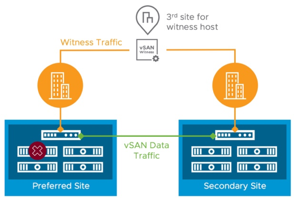
At the time of this document vSAN currently supports up to 15 hosts per site. In addition to the hosts at each site, a "witness" must be deployed to a third site. The witness is a VM appliance running ESXi that is configured specifically for use with a vSAN stretched cluster. Its purpose is to enable the cluster to achieve quorum when one of the two main data sites is offline. The witness also acts as “tie-breaker” in scenarios where a network partition occurs between the two data sites. This is sometimes referred to as a “split-brain” scenario. The witness does not store virtual machine data such as virtual disks (VMDK files). Only metadata such as witness components are stored on the witness.

Up to 200ms RTT latency is supported between the witness site and data sites. The bandwidth requirements between the witness site and data sites varies and depend primarily on the number of vSAN objects stored at each site. A minimum bandwidth of 100Mbps is required and the general rule of thumb is at least 2Mbps of available bandwidth for every 1000 vSAN objects. The vSAN Stretched Cluster Bandwidth Sizing Guide provides more details on networking requirements.
vSAN Stretched Cluster Fault Domains
A vSAN stretched cluster consists of exactly three fault domains. The physical hosts in one data site make up one fault domain; the physical hosts at the other data site are the second fault domain; the witness is the third fault domain.
When a VM is deployed to a vSAN stretched cluster, a RAID-1 mirroring policy is applied to the objects that comprise the VM. One copy of each object such as VM Home and VMDKs are placed on hosts in the first data site; another copy of these objects are placed in the second site; witness objects are placed on the witness at the third site. If any one of the three sites goes offline, there are enough surviving components to achieve quorum so the objects are still accessible
Stretched Cluster Preferred and Secondary Fault Domains
A vSAN stretched cluster consists of exactly three sites or, more accurately, three fault domains: The Preferred fault domain, the Secondary fault domain, and the Witness fault domain. This short article explains the difference between the Preferred and Secondary fault domains and how this difference affects recovery based on the type of failure.

The screenshot above shows one of the steps in configuring a vSAN stretched cluster. There are two fault domains that store data such as VM Home objects and virtual disks. These are the Preferred and Secondary fault domains.
Currently, only the RAID-1 mirroring rule with Number of Failures to Tolerate = 1 are supported with a vSAN stretched cluster. That means one copy of the data is stored in the Preferred fault domain, one copy is stored in the Secondary fault domain, and the witness component is stored on the Witness host. This component distribution provides resilience against a disk failure, host failure, and the loss of an entire site (fault domain).
Back to the original question: What is the difference between the Preferred and Secondary fault domains?
When network connectivity between the Preferred and Secondary fault domains is lost, vSAN is no longer able to write data to both copies of an object. Keep in mind vSAN data is not accessible if vSAN is unable to achieve quorum (access to more than 50% of the components that make up an object). The Preferred or Secondary fault domain must combine with the Witness host (third fault domain) to achieve quorum.
vSAN will automatically select the Preferred fault domain in this scenario. VMs running in the Preferred fault domain will continue to run without interruption. vSphere HA powers off VMs running in the Secondary fault domain and they are restarted in the Preferred fault domain. This is to preserve data integrity with minimal downtime.
When network connectivity is restored between the Preferred and Secondary fault domains, changes at the Preferred site are synchronized to the Secondary site and operations return to normal (writes occurring synchronously to both sites). vSphere DRS affinity rules can be used to automatically migrate specific VMs back to the Secondary site.
As you can see, the concept of the Preferred and Secondary fault domains for vSAN stretched clusters is fairly simple: vSAN "prefers" running all of the VMs in the Preferred fault domain when there is a loss of network connectivity between the two data sites/fault domains
vSAN Stretched Cluster Failure Scenarios
Keep in mind the following when it comes to storage policies and component placement in a stretched cluster: RAID-1 mirroring is currently the only fault tolerance method that can be used. Erasure coding requires a minimum of four fault domains. A vSAN stretched cluster only has three fault domains - the preferred, secondary, and witness fault domains. Components that make up objects such as virtual disks are distributed across the sites, i.e., fault domains, to help ensure availability. One copy of each object is placed in the preferred fault domain. A second copy of each object is placed in the secondary fault domain. A witness component for each object is located on the witness VM at a third site.
Storage Device Failure
Normally in a stretched cluster, all reads are performed locally and writes occur at both sites synchronously. In other words, a VM in "Site A" will read from "Site A" and write to "Site A" and "Site B". When a disk goes offline, vSAN will continue to read from and write to the other copies of impacted objects. Reads will occur across the site link if a VM is running in one site and the accessible copy of the VM's object is located at the other site. If the vSAN cluster is a hybrid configuration, the read cache for the affected VMs will need to be re-warmed, which can impact performance for a brief amount of time.
The second copy of the object will be rebuilt on one or more healthy disks in the same site after 60 minutes if the failed disk is marked as absent. The rebuild will start immediately if the failed disk is marked as degraded.
Behavior in a host failure scenario is similar to a storage device failure. The main difference is host failure will, of course, impact VMs running on the failed host. vSAN and vSphere HA are tightly integrated. These VMs are automatically restarted by vSphere HA on other nodes in the cluster.
Naturally, a host failure will likely have a larger impact than a single disk failure as there are commonly multiple disks in each host. If a host is offline for an extended period of time or permanently, rebuilds will probably take considerably longer than what would be observed with the loss of a single disk. Note that vSAN prioritizes normal production traffic higher than rebuild traffic to minimize any potential performance impact from having to rebuild large amounts of data.
Host Failure

Behavior in a host failure scenario is similar to a storage device failure. The main difference is host failure will, of course, impact VMs running on the failed host. vSAN and vSphere HA are tightly integrated. These VMs are automatically restarted by vSphere HA on other nodes in the cluster.
Naturally, a host failure will likely have a larger impact than a single disk failure as there are commonly multiple disks in each host. If a host is offline for an extended period of time or permanently, rebuilds will probably take considerably longer than what would be observed with the loss of a single disk. Note that vSAN prioritizes normal production traffic higher than rebuild traffic to minimize any potential performance impact from having to rebuild large amounts of data.
vSAN 7 U2 makes a significant improvement to ensuring the latest written data is saved redundantly in the event of an unplanned transient error or outage. When an unplanned outage occurs on a host, vSAN 7 U2 will immediately write all incremental updates to another host in addition to the other host holding the active object replica. This helps ensure the durability of the changed data in the event that an additional outage occurs on the other host holding the active object replica. This builds off of the capability first introduced in vSAN 7 U1 that used this technique for planned maintenance events. These data durability improvements also have an additional benefit: Improving the time in which data is resynchronized to a stale object.
Local Network Failure
If there is a network failure within a site (inter-site link is still intact), vSAN will respond as described in the vSAN Failure Handling guide. in the case where one or more hosts are isolated from the rest of the hosts at the same site, the isolated hosts will form a separate network partition group until the network issue is resolved. The isolated host(s) will lack the necessary number of components/votes (greater than 50%) to achieve quorum. vSphere HA will power off the VMs on the isolated hosts and attempt to restart the VMs on other hosts that have proper network connectivity in the cluster.
Preferred or Secondary Site Failure

When the preferred or secondary site (fault domain) goes offline, it is still possible for vSAN to achieve quorum using the components at the healthy site and the witness components. vSphere HA automatically restarts the VMs that were running at the offline site. VMs running at the healthy site continue to run without downtime. When the offline site is returned to normal operation, all changes at the healthy site are sync'd between both sites.
DRS affinity rules can be used to automate the process of migrating running VMs back to their original location after a site outage has been resolved. This click-through demo shows the process of configuring a vSAN stretched cluster, its behavior when a site goes offline, and the return to normal operations when the failed site is back online.
Witness Site Failure

Loss of connectivity to the witness VM has minimal impact on the VMs running in a stretched cluster. VMs continue to run and all data remains accessible. If the witness VM lost connectivity with the preferred and/or secondary site, vSAN is still able to achieve quorum between the preferred and secondary sites.
If the witness VM is lost permanently, a new one can be deployed with minimal effort. Witness components and vSAN metadata will be re-sync'd with the new witness.
Something else to keep in mind is the witness must be able to communicate with both sites to participate normally in the cluster. If it is unable to communicate with the preferred and secondary fault domains, the witness is removed from the cluster. The witness will automatically rejoin the cluster when connectivity to both sites is restored. vSAN verifies connectivity between sites through the use of "heartbeat" packets. These are transmitted between sites once per second. If five consecutive heartbeats are missed, the connection is down from a vSAN perspective.
Site Failure followed by Witness Failure
vSAN 7 U3 improves the availability of data if one of the data sites becomes unavailable, followed by a planned, or unplanned availability of the witness host appliance. This is achieved through vSAN's Adaptive Quorum Control mechanism, that adjusts the votes on the objects when a data site is offline. This helps improve data availability by allowing for all site-level protect VMs and data to remain available if one data site is offline, and the witness host appliance becomes offline at some period thereafter. This capability mimics similar behavior found in storage array-based synchronous replication configurations. This feature is not only applicable to stretched clusters, but this new logic will work with vSAN 2-node clusters as well. Note that this Adaptive Quorum Control mechanism is only used when the data site is offline prior to the witness site. It does not perform any adjustments of votes if the witness host appliance is offline first.
2-Node VSAN
Many customers have found a vSAN 2-node topology to be extraordinarily effective for remote and edge use cases. 2-node topologies are highly effective at providing resilience in the event of a single host failure, but with vSAN 7 U3, we’ve enhanced this capability to include secondary levels of resilience. Much like vSAN stretched clusters, 2-node topologies can now offer a secondary level of resilience when they have 3 or more disk groups in a host. This means that a topology could suffer an entire host failure, a subsequent failure of a witness, and failure of a disk group on the remaining host, yet still provide full data availability. 3 Disk groups are required for RAID 1 protection within a host, or 4 Disk groups for RAID 5 protection within a host.
HCI Mesh Considerations
HCI Mesh leverages existing vSphere HA and vSAN availability concepts to provide both compute and storage high availability. vSphere HA will provide compute availability on the client cluster, and vSAN storage policies with FTT=N configured will provide storage availability on the server cluster. If the network connection between a client and server cluster is severed, the remote vSAN datastore on a client host will enter APD 60 seconds after the host becomes isolated from the server cluster. After that, vSphere will follow the current HA mechanisms for APD events and attempt to restart VMs after a 180 second delay.
For more information see the HCI Mesh Tech Note, or the vSAN FAQ.
Data Protection and Disaster Recovery
In this last section we will briefly discuss data protection, replication, and disaster recovery. This is just a sample of the various solutions and options that are available both from VMware and its massive ecosystem of data protection and disaster recovery partners.
Data Protection
VMware vSphere includes vSphere APIs for Data Protection (VADP), which provides a framework and mechanisms such as Changed Block Tracking (CBT) to data protection vendors including Dell EMC, Veeam, Symantec, Commvault, and IBM to name just a few. These vendors utilize the APIs and redistribute code provided by VMware to enable efficient backup and recovery of virtual machines. The use of VADP also helps ensure compatibility with a number of features such as vMotion and various vSphere storage types including vSAN. In other words, the majority of backup solutions are able to back up VMs on vSAN the same as traditional VMFS and NFS datastores.
An important thing to point out here is that backup vendors provide the products. VMware simply provides the APIs. Each vendor utilizes the APIs in different ways. Therefore, it is up to the vendors to test/certify their solution(s) and provide support statements to their customers. As such, backup vendors also provide support for their products.
A number of vendors support backing up VMs residing on vSAN datastores. Be sure to check with your backup vendor to determine version requirements and best practices for deployment and operations.
Snapshots
The snapshot architecture used in previous editions of vSAN can be thought of as an enhanced form of a redo-log based snapshot architecture that has been a part of vSphere for many years. While vSAN introduced the “vsanSparse” snapshots to alleviate some of the technical implications of traditional, redo-log based snapshots, these improvements had limits in meeting today’s requirements in performance, scalability, and use cases. VMware does not recommend using VM snapshots as backups. The snapshot file is only a changelog of the original virtual disk. It creates a place holder disk to store data changes since the time the snapshot was created. If the base disks are destroyed, the snapshot files are not sufficient to restore a virtual machine.
With vSAN 8, when using the ESA, snapshots are achieved using an entirely different approach from past editions. Instead of using a traditional “chain” of a base disk and delta disks, the snapshot mechanism uses a highly efficient lookup table using a B-Tree. The log structured file system of the vSAN ESA allows for incoming writes to be written to new areas of storage with the appropriate metadata pointers providing the intelligence behind which data belongs to which snapshot. Snapshot deletion times were over 100x faster than previous versions of vSAN snapshots. The new architecture prevents any need of the computational and data movement effort found in a traditional snapshot deletion. Snapshot deletions, merges, or consolidations were one of the most resource intensive activities found in the traditional redo-log architecture, but also one of the most common activities due to how most snapshots are used. When a snapshot is deleted in vSAN 8 using the ESA, the snapshot delete action is largely just a metadata delete activity. It is immediately acknowledged after logically deleted, and at a later time (asynchronously), the metadata and data will be removed.
Replication
There are a number of host-based replication solutions that can be used to replicate VMs such as vSphere Replication and Dell EMC RecoverPoint for VMs. vSphere Replication is an asynchronous replication feature that is included with vSphere Essentials Plus Kit and higher editions of vSphere. Since these solutions are host-based (as opposed to array-based they can replicate VMs residing on just about any type of vSphere storage including vSAN.
Similar to the use of VADP for backup solutions, VMware provides vSphere APIs for IO Filtering (VAIO), which enables solutions such as Dell EMC RecoverPoint for VMs to provide efficient replication and very low RPOs with little or no impact to the protected VMs. For more details on VAIO go to storagehub.vmware.com
vSphere Replication
VMware vSphere Replication is a hypervisor-based, asynchronous replication solution for vSphere virtual machines. It is fully integrated with VMware vCenter Server and the vSphere Web Client. vSphere Replication delivers flexible, reliable and cost-efficient replication to enable data protection and disaster recovery for all virtual machines in your environment.
vSphere Replication 8.1 marks the move from SUSE Linux Enterprise Server (SLES) to Photon OS for the VR Appliance. Photon OS is a lightweight Linux distribution optimized for vSphere with a security-hardened kernel. It will provide enhanced security, stability and make upgrades and patching the appliance easier. This translates to a more secure, stable and easy to manage solution for customers
Disaster Recovery
The keys to a good disaster recovery (DR) solution are speed and reliability. Naturally, organizations want to minimize downtime in the event of a disaster by using tools that provide the fastest recovery times. Automation is the main ingredient that facilitates speed of recovery. Reliability of a DR plan is just as important as speed. Frequent testing is the best way to help ensure reliability - especially in IT environments where change is constant.
SRM delivers on both speed through automation and reliability by enabling frequent, non-disruptive DR plan testing. SRM is tightly integrated with vSphere Replication. Multiple groups of protected VMs can be configured and included in one or more recovery plans giving organizations the flexibility needed to satisfy varying DR requirements.
Another important consideration is the speed of the storage at the DR site. This is especially true when recovering larger numbers of VMs, which is effectively a "boot storm". All-flash vSAN configurations are ideal for this use case as shown in this video: Recover 1000 VMs in 26 mins with SRM & VR on vSAN
It is possible to utilize a vSAN stretched cluster and SRM together. The vSAN stretched cluster would provide protection for two sites located relatively close together while SRM with vSphere Replication enables disaster recovery in scenarios where both sides of the stretched cluster are impacted by an event such as a large hurricane or power grid failure. The diagram below provides a simple, high-level look at what this architecture might look like.
Summary
Application uptime and resiliency to failure are key factors of any hyperconverged infrastructure (HCI) storage solution. vSAN is VMware’s software-defined storage solution built from the ground up for vSphere virtual machines. It aggregates locally attached disks in standard x86 servers that are part of vSphere cluster to create a shared datastore. vSAN is compatible and integrated with the entire VMware stack including vSphere, vRealize Operations, and NSX. VM storage provisioning and day-to-day management are controlled through policies that can be created and modified at any time using Storage Policy Based Management (SPBM). Policies are assigned at the VM level. This enables precise control of service levels such as resiliency, space efficiency, and performance on a per VM basis. vSAN delivers enterprise-class features scale and performance making it the ideal storage platform for virtual machines. Together, vSAN, vSphere and Site Recovery Manager provide enterprise-class availability and disaster recovery to satisfy the requirements of the most demanding business critical workloads.