
Planning Highly Available and Mission Critical Microsoft SQL Server on Windows Deployments with VMware vSphere
1. Introduction
Ensuring that SQL Server is highly available is one core tenet of mission critical, along with other concepts like performance and scalability. Deploying SQL Server properly ensures that it achieves the availability, scalability, and reliability that is required to be mission critical. Striking the balance between utilization, availability, performance, and manageability is not an easy task, but achievable if planned correctly. Virtualizing SQL Server under VMware vSphere® can help you achieve that goal even though the standard in many companies is to still use physical servers. Why virtualizing SQL Server deployments?
While physical hardware is a tried-and-true method of deploying SQL Server implementations, there can be complications that are part of the deployment process, such as the wait time between ordering and receiving the hardware, and then the actual IT work that needs to get done including tasks like racking and stacking in the data center. It could be weeks, or even months between the time a system was ordered to when it is ready for end users. The business as a result is often less agile because of this process. In today’s modern world, being less agile can be the difference between success and failure.
Virtualization is one of the best methods of achieving that agility. While virtualization has been around for quite some time, there are many data professionals who are unsure if virtualization is the right way to deploy a database server due to years of fear, uncertainty, and doubt based on misconceptions from a time when things were different years ago such as:
- In the early days of virtualization, the computing world was still largely 32-bit, limiting scalability and density.
- Virtual machines (VMs) at that time were limited in the amount of memory and number of processors, which led to bad experiences with virtualizing database workloads.
- Virtualization was still maturing as a deployment method, so the tools and processes were not as mature as they are today.
Today, those challenges are gone. 64-bit is the standard for server hardware and operating systems. As of SQL Server 2016, Microsoft no longer ships a 32-bit server-based version of SQL Server. Physical servers today have large computing capacity with many cores per physical processor and support for large amounts of memory. Only select applications can push modern hardware to its limits, so finding ways to better utilize that computing power while at the same time increasing agility, performance, and availability but reducing cost is the hallmark of virtualization. As of vSphere 8, the following list shows some of the selected maximums including:
- 768 virtual CPUs per VM
- 24TB of memory per VM
- 896 logical CPUs per Host
- 4,096 virtual CPUs per Host
- 32 virtual CPUs per Core
- 16 NUMA Nodes per Host
- Up to 24TB memory per Host
- 1,024 virtual machines (VMs) per Host
- 96 hosts per VMware Cluster
- 8,000 VMs per VMware Cluster
For the complete list of maximum configurations for all currently supported versions of VMware products and solutions, refer to: https://configmax.esp.vmware.com/guest?vmwareproduct=vSphere
In context of availability, virtualizing also provides other options that could potentially enhance the availability options already supported by both Windows Server and SQL Server. Whether looking to architect a simple availability solution in a single data center, or true business continuity with adding a disaster recovery aspect to the architecture to come online in another site, the availability must meet your needs based on actual requirements.
Whether you are a SQL Server DBA, VMware administrator, architect, or IT decision maker, this paper will help you understand how to architect highly available, mission critical SQL Server solutions utilizing vSphere. Performance and agility aspects as they relate to availability will be presented, but this is not a dedicated performance paper. There is much more in terms of nuances at the Windows Server and SQL Server layers that you will need to know as well; this paper is not meant to be exhaustive, but it covers the most important aspects and provide the specific practices as they relate to vSphere.
2. Supportability and Lifecycle Management
Achieving availability is more than choosing and enabling one or more features at the hypervisor or in the guest VM. When deploying mission critical systems that require both reliability and availability to meet business demand, it is imperative that they are supported end-to-end from all vendors. VMware makes this process easier by publishing clear guidelines via their Compatibility Guides (http://www.vmware.com/guides.html). The VMware Compatibility Guide (https://www.vmware.com/resources/compatibility/search.php) allows you to search for a specific combination of VMware products, releases, and more, to determine if your proposed solution is proper and supported. As an example, if you were looking for certified Cisco blades for vSphere 8.0 U1, your query would look like what’s shown in Figure 1 below.

Figure 1 - Querying the VMware Compatibility Guide
The results would look like what’s shown in Figure 2 below.

Figure 2 - Results of the Compatibility Guide Query
The supported versions of Windows Server are also covered by the Compatibility Guide. Under the Compatibility Guide link above, use Guest OS for the value next to What are you looking for. Figure 3 shows the output of a query for Windows Server 2022.
Note that under OS Family Name, if you are going to use older, unsupported versions of Windows Server such as Windows Server 2008 R2 or Windows Server 2012 R2, VMware considers them from a supportability standpoint to be the same as their non-R2 variants for this tool. From a Microsoft standpoint, they are completely separate releases, not point releases despite the R2 designation.
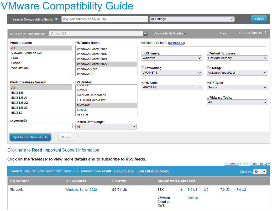
Figure 3 - Querying to Find Which Versions of vSphere Support Windows Server 2022
SQL Server must be supported by the target Windows Server OS. Figure 4 below shows the major version of SQL Server and the versions of Windows Server that support them, starting with SQL Server 2008 and Windows Server 2012 (see https://learn.microsoft.com/en-US/troubleshoot/sql/general/use-sql-server-in-windows).

Figure 4 - SQL Server to Windows Server Support Matrix
To determine the minimum version of SQL Server required by Windows Server 2022 or later, consult the Microsoft Knowledge Base article “Using SQL Server in Windows”. For example, SQL Server versions older than 2017 are not supported on Windows Server 2022, which is the latest version of Windows Server as at the timing of this writing.
Similarly, the table above shows that SQL Server 2022 (the latest version available as of this writing) is only supported on Windows Server 2022, 2019 and 2016 – it is not supported on Windows Server 2012 R2 or Windows Server 2012.
Platform choices are ones that you live with for several years, and the goal is that every component should be supported end-to-end for its entire lifecycle. Microsoft publishes lifecycle guidelines for all of its products including SQL Server and Windows Server at https://learn.microsoft.com/en-us/windows/release-health/windows-server-release-info?source=recommendations. As of the writing of this paper, Windows Server versions earlier than Windows Server 2019 are out of mainstream support, meaning the minimum Windows Server version you should consider deploying under VMware is Windows Server 2019 (Windows Server 2016 is out of mainstream support and is now supported only on “Extended Support” basis). With the end of mainstream support quickly approaching as of the publication of this paper for Windows Server 2019, VMware highly recommends that customers consider deploying Windows Server 2022 where application compatibility is not an issue.
This is why keeping your infrastructure mission critical is a coordinated effort: all pieces of the puzzle have to come together.
Understand that third party application vendors may dictate what version of SQL Server (including patch level) and/or Windows Server that can be deployed. Keep that in mind as you look at what Microsoft will be supporting as you do not want to find yourself out of support with Microsoft and possibly VMware, but in support with the application vendor. If possible, all of your versions will be currently supported by each vendor.
You should always strive to deploy platforms that are in Mainstream Support from Microsoft and have plans to migrate to later versions as they age into Extended Support. This is a critical aspect of availability as well as security, because if the product is no longer being updated, you may encounter functional or compatibility issues, and possibly violate internal rules around security since the platform may no longer receive security updates beyond the extended support timeframe. The biggest long-term challenge is to find and retain administrators who have the knowledge and desire to manage earlier platforms beyond their expiration date.
Last, but certainly not least, you should follow the guidelines in the Microsoft Support Knowledge Base Article “Support policy for Microsoft SQL Server products that are running in a hardware virtualization environment”.
The cost of migrating and upgrading to later versions of Windows Server, SQL Server, and all of VMware’s products every few years will often be offset by the enhancements that could benefit your environment. You should have a planned obsolescence for versions and a scheduled refresh of hardware.
3. Planning for SQL Server Availability Features Under vSphere
This section provides an overview and understanding of the availability features that would be deployed in a guest VM and how to approach deploying them from a VMware perspective.
3.1 SQL Server Protection Levels
There are three levels of protection that the built-in SQL Server availability features can provide: instance, database, and data.
An installation of SQL Server is known as an instance. Therefore, instance-level protection covers the entire installation of SQL Server. Up to 25 instances are supported on a single Windows Server Failover Cluster (WSFC) that is a single clustered configuration, and 50 for standalone (see “Maximum capacity specifications for SQL Server”) – but that does not mean you should deploy the maximum number of instances on a WSFC or a single server. Deploy as many as needed for the business, taking into account manageability, performance, and availability. An instance of SQL Server is the equivalent of a database in Oracle.
There are two types of instances: default and named. A default instance on a standalone server has the same name as the underlying Windows Server. For example, if a server’s name is ALLAN, the name ALLAN is used by applications or end users to access the SQL Server instance. A standalone or clustered configuration can only have one default instance. A clustered instance, also known as a failover cluster instance, works slightly differently, and that will be discussed in Section 3.2.2.
A named instance adds a unique identifier when accessing it, otherwise if you have more than one instance, you cannot get to the data. This unique name is recognized by SQL Server only. It is not registered anywhere else in your infrastructure. Both clustered and standalone solutions can have all named instances, or one default instance and the rest named if there is more than one installation on that standalone server or cluster.
If the underlying server is named ALLAN and there are two named instances installed – HIRT and BOSTON – an application would access them via name using ALLAN\HIRT and ALLAN\BOSTON. When there are multiple instances installed, each gets its own set of binaries, but there are also shared files which are common to all instances. As with a default instance, FCIs have a slightly different behavior with named instances that will be discussed in Section 3.2.2.1.
Database-level protection ensures that specially configured copy of a database can be brought online in another SQL Server instance on a separate server (physical, virtual, or cloud-based). Bringing one or more databases online is just part of the process; there are objects in the instance that will be required to also be configured on that other instance for the application to work properly after switching. The process for this is not part of database-level protection, and DBAs must handle this manually. A database in SQL Server is the equivalent of a schema in Oracle.
Data-level protection ensures that business critical data also exists in a database on another instance of SQL Server and is accessible. Similar to database-level protection, there are other objects in SQL Server that may be required to use the data, and features that fall in this category generally do not make good candidates for making an exact replica of everything in the primary database since it was not designed for that type of protection.
The three levels of protection map to the availability features provided by SQL Server. Table 2 shows the level to feature mapping.
Table 1. Protection Mapping to SQL Server Availability Features
|
Protection Level |
SQL Server Availability Feature |
|
Instance |
Always On Failover Cluster Instance Note: Starting with SQL Server 2012, Always On Availability provides instance-level high availability. |
|
Database |
Always On Availability Group (SQL Server 2012 and later) Basic Availability Group Database Mirroring (deprecated in SQL Server 2012) Log Shipping |
|
Data |
Replication (SQL Server’s built-in feature, not hardware or non-SQL Server software-based) |
This availability section will focus primarily on Always On failover cluster instances (FCIs) and availability groups (AGs) as they are the most widely used availability features in SQL Server. Because both of these features require that Windows Server is clustered underneath them, there are some additional considerations that you must take into account when deploying a clustered configuration of Windows Server and SQL Server underneath. You cannot deploy an availability group or clustered instance of SQL Server without clustering Windows Server first as a WSFC.
Inside the VM, clustering is a stack. This can be seen in Figure5.

Figure 5. Clustering Stack for SQL Server as It Relates to vSphere
The other availability features – database mirroring, log shipping, and replication – will only be discussed briefly. Database mirroring (DBM) was deprecated in SQL Server 2012. Underneath the covers, how it works is similar to (but not exactly the same as) an Availability Group because some of the underpinnings are similar, such as the way that the log records are sent to the mirror. Log shipping is based on SQL Server’s native backup and restore, so there is not much special that needs to be done from a virtualization standpoint. Many of the generic best practices that will be discussed in this paper could apply, but log shipping itself does not complicate a deployment. SQL Server’s replication feature has a few different variants (snapshot, merge, and transactional), but is not designed to provide availability like the database-level features. These three SQL Server availability features will not be discussed further in this paper.
Always On is Microsoft’s formal marketing umbrella which encompasses both the availability groups feature as well as clustered instances of SQL Server; it is not the AG feature. Prior to late 2015, the Always On marketing moniker did not include a space. Since a clustered installation of SQL Server can either be an FCI or use an AG, using something like SQL Clustering would be incorrect, and using AAG, AOAG, or another variant for AG is not correct either. With the SQL Server availability features, using the right names helps keep everyone on the same page. If you see incorrect names for these features, refer back to this paper to know how it maps properly to how Microsoft refers to them.
3.2 Planning Clustered Implementations of SQL Server under vSphere
A base WSFC only provides availability. It does not provide scale out or load balancing capabilities. Workloads running on top of a WSFC may add these as part of what they provide, but the general rule of thumb for deploying SQL Server is that you must properly size and scale up an AG or FCI. A server or VM participating in a WSFC is known as a node. It is a general best practice to ensure that each node participating in a clustered SQL Server has the same configuration.
Always refer to VMware Knowledge Base article “Microsoft Cluster Service (MSCS) support on ESXi (1004617)” for the latest information on supported configurations of Microsoft clustered configurations under vSphere.
3.2.1 Deploying a Windows Server Failover Cluster
This section will help you plan a base WSFC configuration for an AG or FCI under vSphere.
3.2.1.1. Windows Server Edition, Number of Nodes, and Supportability
Windows Server 2008 R2 and earlier requires Enterprise or Datacenter Editions to be able to create a WSFC (formerly known as Microsoft Clustering Service (MSCS) in these versions). Windows Server 2012 and later can use either Standard or Datacenter Editions.
Windows Server 2012 and later can support up to 64 servers, known as nodes, in one WSFC. VMware ESXi™ supports up to 16 VMs in a single FCI’s configuration.
Current Microsoft documentation treats FCIs and AGs as mutually exclusive and could potentially be interpreted in different ways for the total number of nodes. For a configuration with shared storage, meaning an FCI, the maximum number of nodes depends on the SQL Server edition. For SQL Server 2022 Enterprise edition, it is whatever the Windows Server edition supports. For SQL Server 2022 Standard edition, the maximum is 2 nodes.
See the following applicable references for more details:
- Editions and supported features - SQL Server 2016 | Microsoft Learn
- Editions and supported features - SQL Server 2017 | Microsoft Learn
- Editions and supported features of SQL Server 2019 - SQL Server | Microsoft Learn
- Editions and supported features of SQL Server 2022 - SQL Server | Microsoft Learn
Since an AG can support up to the maximum number of replicas, the total number of VMs in a WSFC configuration should not be a concern, even if combining one or more FCIs are part of an AG. However, if there is any confusion, you should contact VMware support to ensure that your proposed solution is one that will be supported. Since Microsoft supports up to 64 nodes in a WSFC and SQL Server’s number of nodes varies per feature, your limitation will come in based on if you are deploying an FCI and whether you have shared storage. To ensure that a WSFC configuration is supported by Microsoft, a process called validation was introduced in Windows Server 2008. It validates the proposed configuration of the WSFC before creating it. If the validation tests show that the configuration is fine, the VMs can be clustered as a WSFC.
As virtualization became widely adopted, Microsoft introduced the option to skip certain parts of the cluster validation process and interpret certain findings differently, particularly for components that are outside the scope of Microsoft’s control or responsibility. The support for these components has shifted to third-party vendors like VMware. Microsoft also updated its guidance on required actions to take when a test fails. In all, Microsoft no longer prevents cluster setup solely based on a failed test report or when tests are skipped.
VMware continues to recommend that customers perform cluster validation before setting up their cluster on VMs hosted on VMware vSphere. When using Raw Device Mapping (RDM) for storage presentation to the nodes, the cluster validation wizard may report an error on the storage test. This is because the Wizard has no notion of this valid storage option. It is ok to skip this test entirely or ignore the warning.
Microsoft deprecated clustering-related features in Windows Server 2022. However, the cluster validation Wizard still checks for some of these features when validating a cluster setup on Windows Server 2022. For example, Microsoft removed the “LBFO” feature and replaced it with “Switch Enabled Teaming Configurations”, a Microsoft hypervisor feature which does not exist in VMware vSphere. Because the wizard checks for this feature on all Windows OS instances, regardless of the underlying hypervisor platform, the wizard generates a “Switch Enabled Teaming (SET) Configurations” warning during the validation process.
While it is likely that that this issue will be fixed in future Windows Server 2022 updates, it is unlikely that such fixes will be backported to earlier versions of Windows. It is safe to ignore this error or unselect the check for this feature before performing the validation test. See Figure 6 below:

Figure 6 - Validation Wizard Checks for SET
WSFC nodes could be all physical, all virtual, or a mix of physical and virtualized nodes as long as that validation process is run and satisfies the supportability laid out by Microsoft in the Support policy for clustered configurations - SQL Server | Microsoft Learn. A mixed WSFC of physical nodes with VMs in vSphere is supported with vSphere 5.5 or later.
3.2.1.2. Active Directory Domain Services and Domain Name Services
Beginning with Windows Server 2016, Microsoft introduced the “Active Directory-Detached Cluster” feature in WSFC. This allows for the creation of WSFC with nodes which do not belong to an Active Directory Domain (a “Workgroup Cluster”, so to speak). A Workgroup WSFC allows for the configuration SQL Server Always On Availability Group in which none of the nodes is a domain member (this configuration is called “Domain Independent Availability Group”) – identical to “normal” Availability Group for all intent and purposes, except for the domain membership requirement. A similar but limited, less robust configuration option was introduced in Windows Server 2012 and SQL Server 2012.
Except for scenario described in the preceding paragraph, WSFC requires both Active Directory Domain Services (ADDS) and Domain Name Services (DNS). DNS does not have to be Microsoft’s implementation. Both ADDS and DNS should be redundant to ensure that your infrastructure, especially WSFCs, can access them if required. In ADDS, corresponding objects are created for any resource that is a name, and subsequently, that name and its associated IP address are stored in DNS.
3.2.1.3. Networking
Prior to Windows Server 2008, the traditional way to configure a WSFC was to have two separate networks, each on its own subnet:
- One for external traffic, commonly known as the public network
- One for intra-cluster traffic only, commonly known as the private or heartbeat network
This configuration also assumes that underneath those two networks, there are separate network cards. Each network card is plugged into a different physical switch, and so on. This configuration ensures that a WSFC’s networking is not a single point of failure and the WSFC nodes can still communicate even if one of the networks is down. Translated to the virtualized world, it would look as Figure 7.
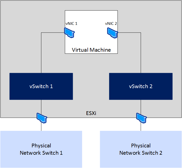
Figure 7. Example Logical Network Topology for a WSFC Node
With the introduction of validation in Windows Server 2008, Microsoft still checks for redundant networking but will allow a configuration that does not have it. In the software defined world, mapping back to physical networks is not the same as it would be if you had physical NICs. This can be even more abstracted when you have a blade-based system where the network connections are aggregated in the chassis. The reality is that a vNIC generally cannot fail in the same way a physical network card can.
Microsoft no longer requires more than one NIC for WSFC and the concept of “dedicated heartbeat NIC” has been obviated by the fact that, even if you designate one NIC as such, WSFC will still use that NIC for normal, “public” traffic in normal operations.
If you configure a single vNIC on VMs that will be part of a WSFC, validation will still generate a warning if it sees a single network for the WSFC. If you knowingly created this configuration, this would be expected. At the top of the report, you will see that the network category has a warning similar to the one in Figure 8.

Figure 8. Network Validation Category Reflecting a Warning
Clicking on Network, it will bring you down to the section which has a list of the tests that were run. In this case, you can see in Figure 9 that Validate Network Configuration is the test that generated the warning.

Figure 9. Validate Network Communication with a Warning
Drilling down further, in Figure 10, you can see the warning messages generated due to the single vNIC that is configured. The two highlighted messages are identical, and are reporting that it only sees one NIC, and it could be a single point of failure.

Figure 10. Single vNIC Warnings
If you have followed the prescriptive guidance on networking configuration in a vSphere infrastructure, this configuration is perfectly acceptable because the networking is fully redundant underneath that single vNIC. If, however, that vNIC is connected to a vSwitch (or vSphere Distributed Switch) which is incorrectly mapped to a single physical NIC, that means a network blip could possibly take down your WSFC, and subsequently, an AG or FCI configured on it. If this is your configuration, do not cluster Windows Server and create an AG or FCI; you are not highly available nor redundant at the network layer.
In a similar fashion, a single physical NIC inside a vSphere host that has multiple ports connected to multiple physical switches is also a single point of failure. The ports are physically considered separate, but the card itself is the single point of failure. Keep in mind that if you are using blades, the blades share an enclosure and backplane, which would include all networking.
One way to create redundancy at the vSphere level is to team the NICs in ESXi (follow KB 100488). Teaming NICs may also provide higher bandwidth since they can usually be configured in one of three ways: failover, load balanced, or a combination of both (which is generally recommended) depending on the functionality provided by the driver or software. Microsoft also supports teaming of NICs inside guests, and if you do, it is recommended to use the built-in teaming provided by Windows Server in Windows Server 2012 or later.
3.2.1.4. Quorum
To help ensure that the WSFC is up and running, it employs a mechanism known as quorum. If you lose quorum, the WSFC and anything running on top of it (such as an AG or FCI) will also be brought offline. Quorum makes use of another resource called a witness, which can be a disk, a file share, or in Windows Server 2016 and later versions, a cloud witness in Microsoft Azure. For a file share, the share must be a Server Message Block (SMB) 3.2 or later share that should be highly available. Discussing quorum in-depth is out of scope for this paper. For more information, see the links at the end of the document. The one method that would require more special attention would be a disk-based witness. How to approach shared disk storage will be covered in Section 3.2.2.2.
3.2.1.5. Cluster In a Box, Cluster Across Boxes, Number of Hosts, and Node Placement
vSphere has two ways to create a WSFC which are VMware concepts: cluster in a box (CIB) and cluster across boxes (CAB). CIB is when all WSFC nodes are on the same physical host. CAB is when the WSFC nodes are placed on different hypervisor hosts. These terms can apply to both AG and FCI configurations under vSphere. CIB is generally not recommended for a production environment as the ESXi host is a single point of failure but would be more than acceptable for test configurations. CIB is also not supported for FCI configuration, when the underlying storage is presented as RDM.
In either configuration, you must configure an affinity or anti-affinity rule for the nodes to keep them together (CIB) or separate (CAB). For CAB, configuring the proper anti-affinity rules ensures that the virtualized WSFC nodes cannot run on the same hypervisor host. This will impact the number of hosts that will be required, and dictate how VMware vSphere Distributed Resource Scheduler™ (DRS), VMware vSphere High Availability (HA), or VMware vSphere vMotion® can ultimately be used. For CIB, configuring affinity ensures that the nodes will be kept on the same host.
For example, if you have two WSFC nodes comprising a FCI configuration that should be CAB, you will need at least three vSphere hosts so that, in the event of one of the hosts failing that was running one of the WSFC nodes, that VM can be started on the third host. If the active WSFC node is the VM on the failed ESXi Host, the WSFC mechanisms would take over first and move the clustered resources over to the peer (passive) node during this failure. When the node from the failed host is restarted elsewhere, it would no longer be the one owning the resources in the WSFC.
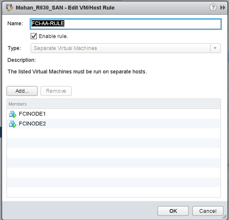
Figure 11. DRS Anti-affinity Rule for Two WSFC Nodes in an FCI Configuration
To ensure that vSphere HA and vMotion respect the affinity/anti-affinity rules, you must also set the appropriate vSphere HA rule settings as shown in Figure 12.
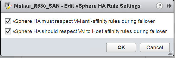
Figure 12. vSphere HA Settings for Anti-affinity for WSFC Nodes Set for a CAB Configuration
One thing to note is that VMware strongly recommends that you should not over-commit memory resources on an ESXi Host or in a vSphere Cluster which contains WSFCs VMs. If ESXi memory over-commitment is unavoidable, VMware recommends that you should reserve all the memory allocated to the WSFC VMs to ensure that they always have entitlement on the resources. See “Setup for Failover Clustering and Microsoft Cluster Service” for additional information.
3.2.2 Always On Failover Cluster Instances
FCIs are historically the most common form of a clustered SQL Server configuration, whether physical or virtual. A WSFC with a one clustered instance of SQL Server is known as a single instance failover cluster. If you have more than one instance, that FCI configuration is known as a multiple instance failover cluster. Using active/passive and active/active are not correct since you can have more than two nodes and/or two instances in a WSFC. For more information on the proper terms for FCIs, see the links later in the paper. SQL Server Standard Edition supports a two node FCI, while Enterprise Edition supports up to the maximum number of nodes supported by the underlying Windows Server version and edition.
FCIs remain popular even under VMware because, in a failover of the instance (planned or unplanned), it restarts automatically on another node and there is no need to worry if everything needed (such as logins, SQL Server Agent jobs, and others) is there. It also provides availability and minimal downtime when the underlying Windows Server installation needs to be patched since you can just fail the FCI over to another node. The VMware options protect the VM itself but would not protect against downtime due to application-level outages or a component failure in the Windows Server OS which does not trigger a complete outage.
3.2.2.1. ADDS, DNS, and FCIs
An FCI also gets its own unique name that gets an object in AD, DS, and DNS. This also means that at least one IP address must be assigned to an FCI. If a WSFC is multi-subnet, more than one IP address can be assigned. Each IP address and name are different from the names and IP addresses of the WSFC and the underlying nodes. For example, if the nodes are named PHILLY and SOUTHJERSEY, and the WSFC is named BFBRIDGE, the name for the FCI could be LIBERTYBELL. LIBERTYBELL would then get an object called the virtual computer object (VCO) that is a child to the CNO.
If the instance is a default instance, it would be accessed via LIBERTYBELL, not the other names. A named instance would have the additional name after a slash as noted above, such as LIBERTYBELL\MUSEUM. Installing another FCI in the same WSFC would require an additional unique name and IP address(es).
3.2.2.2. Storage for FCIs
For the main data and log storage used by FCIs, it requires some sort of storage that is accessible by all of the nodes. Storage is a single point of failure in an FCI configuration. From an in-guest perspective, this can be done via the following methods shown in Table 2 below.
Table 2. SQL Server FCI Shared Disk Options per Version for a WSFC
|
Drive Letter |
Drive Letter + Mount Point |
SMB 3.0 |
Cluster Shared Volume (CSV) |
Local TempDB |
|
|
SQL Server 2008 |
Yes |
Yes |
No |
No |
No |
|
SQL Server 2008 R2 |
Yes |
Yes |
No |
No |
No |
|
SQL Server 2012 |
Yes |
Yes |
Yes |
No |
Yes |
|
SQL Server 2014 |
Yes |
Yes |
Yes |
Yes |
Yes |
|
SQL Server 2016 |
Yes |
Yes |
Yes |
Yes |
Yes |
|
SQL Server 2017 |
Yes |
Yes |
Yes |
Yes |
Yes |
|
SQL Server 2019 |
Yes |
Yes |
Yes |
Yes |
Yes |
|
SQL Server 2022 |
Yes |
Yes |
Yes |
Yes |
Yes |
Drive letters, drive letter with mount points underneath, and CSV all require that the storage is presented to all of the underlying hosts and then to the VMs participating in that WSFC configuration. For more information on how SQL Server FCIs can use CSVs, see this SQL HA blog post.
See Use Cluster Shared Volumes in a failover cluster for detailed information and considerations for using CSV for Windows Server Failover Cluster.
Presenting that storage is supported under vSphere in the following ways:
- Fibre channel
- Fibre channel over Ethernet (FCoE) – vSphere 5.5 and later supports native; for more information on FCoE see note 4 of Table 1 in the VMware Knowledge Base article “Microsoft Clustering on VMware vSphere: Guidelines for supported configurations”.
- iSCSI – native (vSphere 5.5 or later) or in-guest. If using iSCSI inside the guest, separate vNICs should be used to connect to a different network than the one used by the nodes for SQL Server or WSFC traffic.
- Physical raw device mapping (RDM, also known as a physical RDM or pRDM)
- Virtual Volumes (vVols) – See Virtual Volumes (vVols) now supports WSFC
- Support for using VMFS-backed storage (VMDKs) for shared-disk WSFC configuration began in vSphere 6.7 U3 (for vSAN storage) and generally from vSphere 7.0, with the introduction of the “Clustered VMDK Datastore” type.
- VMware began supporting VMDK-backed share-disks for FCI on a limited basis in vSphere 6.7, with the release of the vSAN iSCSI feature.
Before vSphere 6.7, the only supported disk option for FCI was Raw Device Mapping (RDM). vSphere 6.7 provided support for VMDKs when presented through the VMware Virtual Volumes storage option. With the release of 6.7 Update 3, this support for VMDKs was extended to VMware vSAN storage.
vSphere 7.0 introduced the “Clustered VMDK” datastore option for SAN-based storage, eliminating the historical requirement for (and dependence on) RDM as the disk presentation option FCI configuration, although RDM continues to be supported in all versions of vSphere.
Use the VMware Paravirtual SCSI (PVSCSI) adapter for the disks that will be used FCI Data and Log files; and for better performance, consider using more than one PVSCSI controller to split up the I/O load for better concurrency. Make sure that you are configuring the PVSCSI adapters properly by following the advice in the following VMware KBs: 1267, 1268, and 2053145, which talk about disk-related configuration topics like queue depth and VMKernel Admittance.
3.2.2.3. Using Native VMDKs for FCIs (vSphere 6.7U3 and Later)
With the release of the “Clustered VMDK” feature in vSphere 7.0, VMDKs can now be successfully shared among/between WSFC nodes natively, with support for SCSI-3 Persistent Reservation capabilities. RDMs are, therefore, no longer required for WSFC shared-disk clustering.
Considerations and limitations for using Clustered VMDKs are detailed in the “Limitations of Clustered VMDK support for WSFC” section of VMware vSphere Product Documentation.
With a few restrictions, you can enable Clustered VMDK support on existing VMFS Datastore. Because Clustered VMDK-enabled Datastores are not intended to be general-purpose Datastores, VMware recommends that, where possible and practical, customers should create new dedicated LUNs for use when considering Clustered VMDKs.
The most common use envisioned for this feature is the support for shared-disk Windows Server Failover Clustering (WSFC), which is required for creating SQL Server Failover Clustering Instance (FCI).
If you must re-use an existing Datastore for this purpose, VMware highly recommends that you migrate all existing VMDKs away from the target Datastore, especially if those VMDKs will not be participating in an FCI configuration. VMware does not support mixing shared VMDKs and non-shared VMDKs in a Clustered VMDK-enabled Datastore.
You can enable support for Clustered VMDK on a Datastore only after the Datastore has been provisioned.
The process is as shown in the images below:
- In VMware vCenter® Client, select the datastore for which you want to enable “Clustered VMDK”.
- Click on the “Configure” tab.
- Click on the “General” section.
- Click “Enable” on the “Clustered VMDK section”, as shown below.

Figure 13 - Enabling Clustered VMDK (Step 1)
- Read the warning, then Click “Enable” to commit the change.
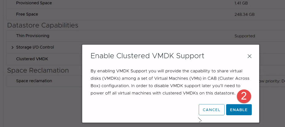
Figure 14 - Enabling Clustered VMDK (Step 2)
- Verify that the status on “Clustered VMDK” is now set to “Enabled”.
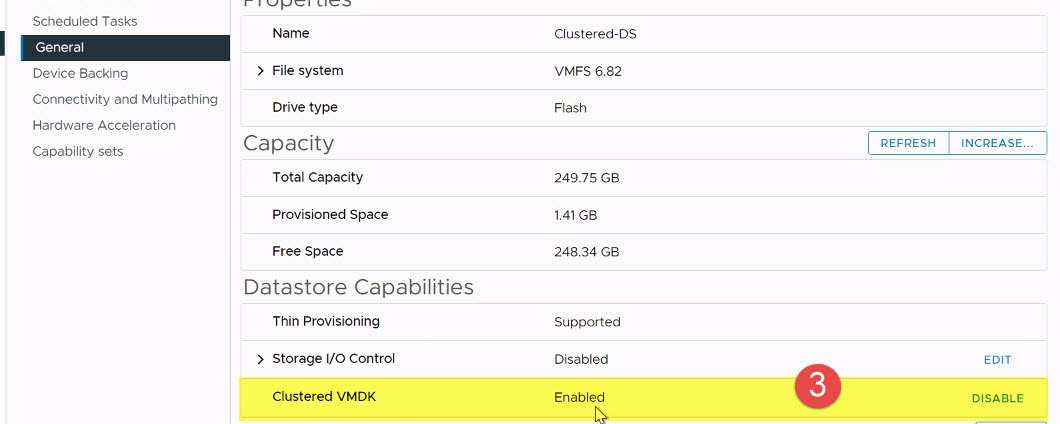
Figure 15 - Enabling Clustered VMDK (Step 3)
Windows Server Failover Clustering uses SCSI-3 PRs commands to coordinate access to a clustered disk resource. These commands (PR-IN and PR-Out) are emulated at VSCSI layer on a datastore. The feature requires support from the datastore perspective. Enabling the “Clustered VMDK” feature on a datastore as shown above is all that is required to satisfy WSFC’s requirements for the datastore to become useful for hosting shared disks (VMDKs) which are required for SQL Server FCI configurations.
3.2.2.4. Provisioning Shared VMDK on First FCI Node
The process of creating and allocating VMDKs in a “Clustered VMDK” datastore is similar in every respect to the process of doing so on any vSphere datastore.
The following is a high-level description of the steps required to create and allocate a VMDK disk to more than once VM in a vSphere environment:
- Right-click and select “Edit Settings” on one of the VMs which will share the disk.
- From the “Add New Device” menu, select “Hard Disk” as shown below.

Figure 16 - Add New Shared VMDK Disk to a VM
- Expand “New Hard disk” and change the Disk size as desired. An example is shown in Figure 17.
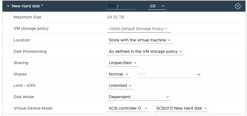
Figure 17 - Specify Desired Disk Size
- Select “Location”, then click “Browse”, as shown in Figure 18.
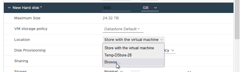
Figure 18 - Browse to Clustered VMDK Datastore
- Select the “Clustered VMDK” Datastore you created earlier. Click OK. An example is shown in Figure 19.
Note: It is very important for you to note this location. This is where you will browse to when you are ready to attach this shared disk to another Node.
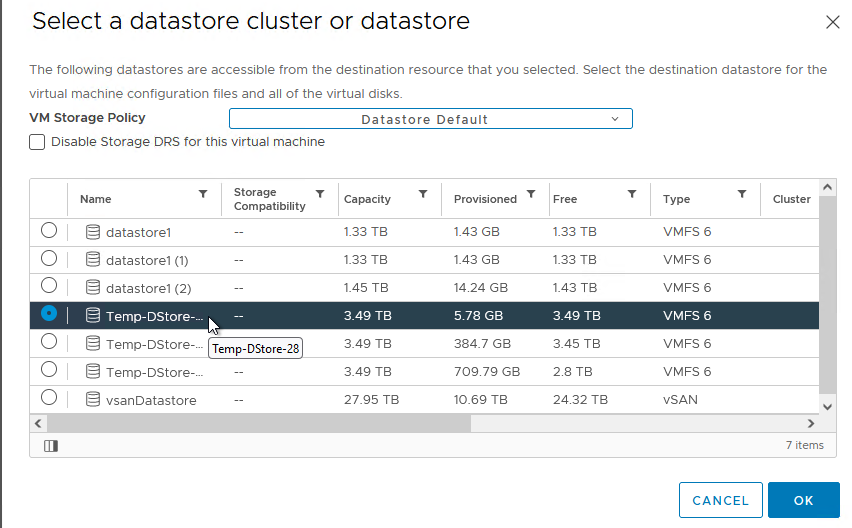
Figure 19 - Select the Clustered VMDK Datastore for the Shared Disk
- Click “Disk Provisioning” and select “Thick Provision Eager Zeroed”, as shown in Figure 20. Even if the backing storage array is all-Flash, Eager Zeroed thick provisioning is recommended for performance and high throughput considerations for Microsoft SQL Server data, logs and TempDB volumes.
Note: Thin provisioned disks are supported only when using vSAN.

Figure 20 - Select Disk Provisioning Format
- Click on “Disk Mode” and change it to “Independent – Persistent”, as shown in Figure 21.
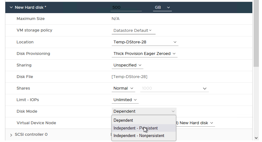
Figure 21 - Specify the Disk Mode
- From the “Virtual Device Node” menu, select the appropriate SCSI Controller ID to which you want to attach the disk, as shown in Figure 22.
Note: It’s important that you record the SCSI ID for this disk. You will need to attach the same disk to the same SCSI channel on all VMs which will share this disk.

Figure 22 - Attach VMDK to the SCSI Controller
- As shown in Figure 23, expand the SCSI Controller to which you have attached the disk, click on “SCSI Bus Sharing” and ensure that it is set to “Physical”. Click OK to commit all the changes.

Figure 23 - Select Controller Bus Sharing Option
When you are done, your configuration should look similar to what is displayed in Figure 24 below:
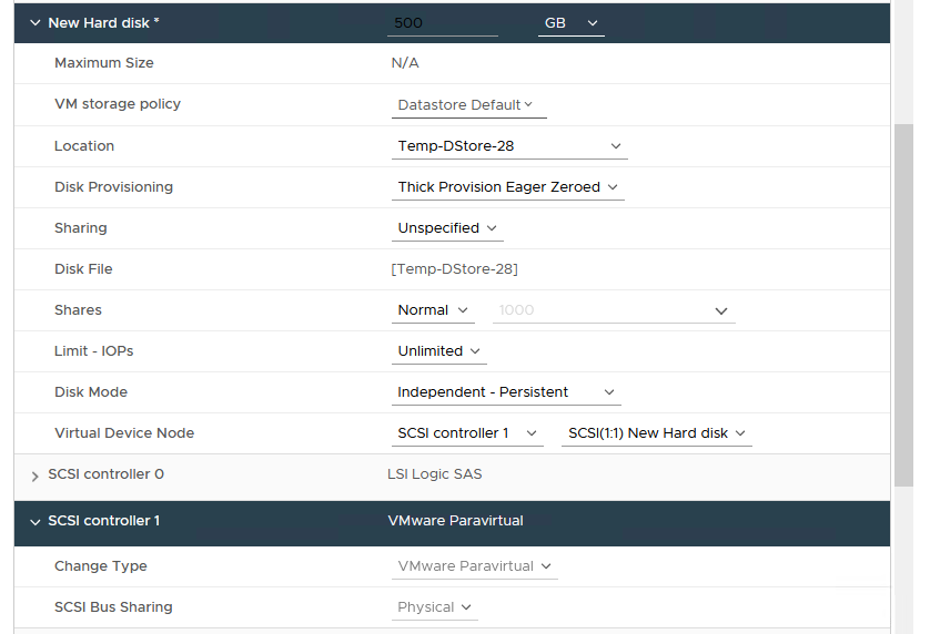
Figure 24 - Sample Shared VMDK Configuration Info
It is recommended that you now power on the VM and format this disk as desired in Windows Server. The same disk can now be presented to additional VMs which will be sharing it.
3.2.2.5. Adding Shared VMDKs to other FCI Nodes
- Right-click and select “Edit Settings” on one of the VMs which will share the disk.
- From the “Add New Device” menu, select “SCSI Controller” as shown in Figure 25:

Figure 25 - Add a Controller to be Used by Shared VMDK
- Expand the new SCSI Controller and change the type to “VMware Paravirtual”. An example is shown in Figure 26.
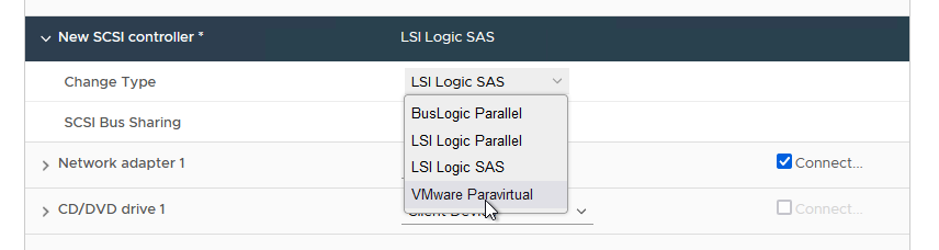
Figure 26 - Change the Type to "VMware Paravirtual"
- Change the SCSI Bus Sharing to “Physical” as shown in Figure 27.

Figure 27 - Change the Bus Sharing Option to Physical
- Click on “Add New Device” again. This time, select “Existing Hard Disk”. An example is shown in Figure 28.

Figure 28 - Add the Shared Disk to Another VM
- As shown in Figure 29, browse to the location containing the disk you are trying to share, then select the right disk (remember that you wrote down the location when you created it in the previous steps).
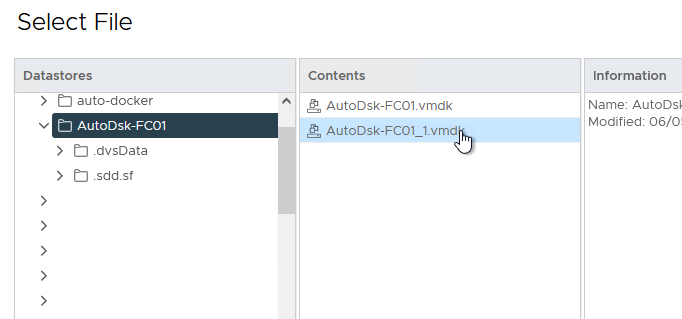
Figure 29 - Select the Correct Disk
- Important: You must ensure that the disk is connected to the same SCSI Bus on this node as it is on the original node. In other words, the SCSI ID must match on all the nodes sharing this disk as shown in Figure 30.

Figure 30 - Review the Settings
- Now, click OK to complete the configuration.
Note: If you have previously formatted this disk in the previous Section, there is no need to do so again on any additional Node. The Disk is now available for use in Windows Server and WSFC configuration. WSFC will arbitrate access to (and ownership) of the Disk as a resource from this point forward.
3.2.2.6. Using Raw Device Mapping-backed Disks for FCIs
If you must continue to use RDMs for your FCI configuration, note that the disks must be attached to a SCSI controller (VMware Paravirtual) and set to physical compatibility mode. An example is shown in Figure 31.
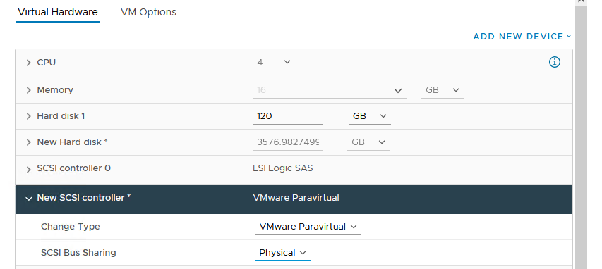
Figure 31 - Attaching RDM to SCSI Controller
To add a RDM disk to the VMs that will be participating in an FCI, follow the instructions below.
- Edit the settings of one of the nodes (it does not matter which).
- Under “Add New Device”, select RDM Disk as shown in Figure 32.

Figure 32 - Selecting RDM Disk
- A list of usable LUNs available will now be displayed. Select the LUN on which to place the RDM, then click OK. An example is shown in Figure 33.
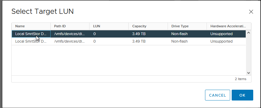
Figure 33 - Selecting LUN for RDM Disk
- Expand New Hard disk. Ensure that Compatibility Mode is set to Physical, the Virtual Device Node is set to the correct PVSCSI controller, and that Disk Mode is set to Independent – Persistent since this is a physical disk. An example is shown in Figure 34.
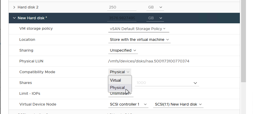
Figure 34 - Configuring the RDM
- Click “Browse” under “Location” to navigate to a compatible Datastore for the RDM’s mapping file as shown in Figure 35.
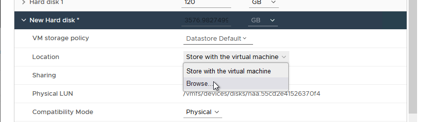
Figure 35 - Browse for Compatible Datastore
- Now, select the appropriate datastore for the RDM’s mapping file. An example is shown in Figure 36.

Figure 36 - Select the Datastore
- Click “OK” to commit the changes.
If you look at the corresponding datastore for the VM, you will see a VMDK with the size of the RDM that was added. This is a “friendly” visual representation in vCenter, as can be seen in the example in Figure 37. What it looks like underneath the covers is a bit different.
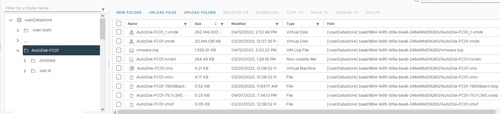
Figure 37 - RDM as Seen in vCenter
Looking underneath the covers, the actual VMDK is a small file (520 bytes). The RDM is represented by a mapping file with a name of friendlyname-rdmp.vmdk format with the size of the underlying LUN. This can be seen in Figure 38.
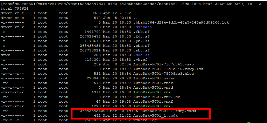
Figure 38 - Files Associated with the RDM as Seen in the Command Line
- On another VM that will be participating in this configuration, instead of adding the RDM Disk, select “Existing Hard Disk” as shown in Figure 39 below.

Figure 39 - Adding an Existing RDM Disk
- Navigate to the disk created earlier and select it, as shown in Figure 40 below. Then, click OK.

Figure 40 - Selecting RDM Disk
- Ensure that the disk is configured identically as in previous steps. Also, ensure that the virtual device node is set to the correct PVSCSI controller ID. An example is shown in Figure 41.
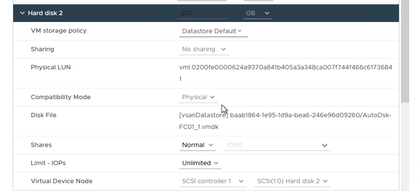
Figure 41 - Configuring the RDM on Additional Nodes
- Click OK to add the RDM to this node.
- Repeat Steps 8—11 for any other VMs which will participate in the FCI configuration.
- When completed, the disk will be available in all of the nodes as shown in Figure 42 and can be configured for use in Windows Server.
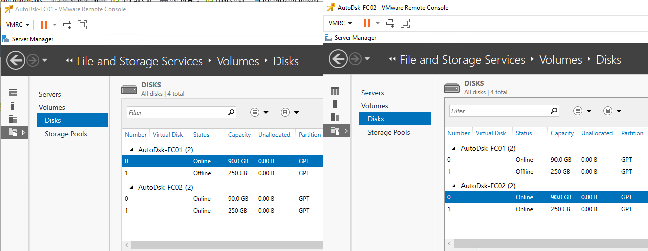
Figure 42 - Shared RDM-backed Disks, As Seen in Windows Server
Remember that, when formatting disks for use with SQL Server, use a 64KB allocation unit size and for the file system, use NTFS, or with SQL Server 2014 or later, you can also use ReFS.
Note: If you are using RDMs and the WSFC node VMs are for some reason on the same host (CIB), you will see errors in validation similar to the one in Figure 43.
Important: Cluster-in-a-Box (“CIB”) configuration is not recommended for important clustered SQL Server workloads. This is because, if the host becomes unavailable, all the clustered nodes become unavailable. CIB does not provide real “high availability”.

Figure 43 - Disk Errors During WSFC Validation
Underneath the covers, vSphere 5.5 and later supports a Path Selection Policy (PSP) of Round Robing (PSP_RR) with shared disks as long as the underlying storage supports it. PSP is set at the host level, and hosts with a different PSP setting running clustered Windows Server VMs is a supported configuration.
If using SMB 3.0 file shares for SQL Server data, log, and backups, VMware only supports it with Windows Server 2012 or later. This is not a Microsoft limitation. This requirement would be true if the data, log, or backups were stored using FCIs or standalone instances of SQL Server.
There are three places where “local” disks can be used with a FCI configuration: for the OS disk, TempDB, which is SQL Server’s temporary workspace, and for the CIB scenario.
The OS disks for each node should not be placed on the same datastores and, where possible, those datastores should not be on the same storage unit. When combining with the data/log/backup RDMs, those disks even though they are technically a single point of failure, should be separate from the OS disks to have some level of redundancy at the storage layer.
If the desire is to create a VMDK to use for TempDB, it should only be done after evaluating that this is required and that you will have enough IOPS to sustain the workload. It also complicates the configuration a bit because it can affect vSphere HA and/or vMotion and have local disks as part of the SQL Server deployment; this will be addressed later in the paper.
If using a drive letter, drive letter + mount point, or CSV, VMware recommends that you should set the following Registry Key (HKEY_LOCAL_MACHINE > System > CurrentControlSet > Services > Disk) value to “60” on each of the WSFC nodes in Windows Server.
3.2.3 Always On Availability Groups
Availability Groups (AGs) are comprised of replicas, with the following limitations:
- One primary and 8 secondary replicas (5 of which can be Synchronous) in SQL Server 2019 and later
- One primary and 8 secondary replicas (3 of which can be Synchronous) in SQL Server 2017
- One primary and 8 secondary replicas (2 of which can be Synchronous) in SQL Server 2016 and 2014
- One primary and 4 secondary replicas in SQL Server 2012
AGs can be combined with FCIs for even more protection inside a guest environment. Unlike FCIs, which are configured at the time of installing SQL Server, an AG can be configured post-SQL Server installation.
AGs have enhancements over other database-level features such as:
- A Listener which, like the unique name for an FCI, provides abstraction for end users and applications to access an instance without having to worry about which node it is running.
- One or more secondary replicas which can not only be used for availability, but also for read only activity as well as backups and DBCCs (these additional uses affect licensing and the choice of SQL Server editions)
- Providing both high availability and functional disaster recovery in the same feature
An AG keeps the secondary replicas in sync by sending the transactions across a log stream. The synchronization can occur synchronously or asynchronously, which means that the network between the VMs participating in an AG has to be robust and reliable. In some cases, this may require an additional dedicated network that could be mapped to an additional vNIC (and possibly a dedicated physical network/VLAN). This would be determined through testing.
In SQL Server 2012 and 2014, AGs are an Enterprise Edition feature. In SQL Server 2016 and later, Microsoft allows you to create an AG (also known as Basic Availability Group), using Standard Edition, but you are limited to a total of two replicas.
3.2.3.1. ADDS, DNS, and AGs
SQL Server 2012 and 2014 require the use of Active Directory Domain Services (ADDS), Domain Name Services (DNS) with all AG configurations. If a Listener is configured, it requires a VCO along with an entry in DNS. See Section 3.2.1.1 for additional information on ADDS and DNS requirements and considerations applicable to AG.
3.2.3.2. Storage and Networking for Availability Groups
Each replica has a copy of the database(s) participating in a given AG. This means that if you have a database that is 2TB, a two-replica configuration will require 4TB of space. An FCI only has a single copy of the data but is a single point of failure.
Despite the increase in storage usage due to multiple copies of the databases participating in an AG, one of the biggest benefits of using an AG under vSphere is that it does not have any special shared storage requirements unless you are combining FCIs with AGs. This means that with vSphere, unless there is reason that RDMs must be used for the SQL Server data and transaction log files (such as combining FCIs and AGs, and using RDMs for the FCI portion), you should use standard VMDKs and VMFS datastores instead of RDMs. This simplifies the planning and configuration and makes AGs a good fit for use under vSphere.
You must plan how the VMDKs would be laid out not only for performance of SQL Server databases and transaction log files, but for availability as well. Placing all of the files on the same datastore on the same storage unit would be a single point of failure.
An example disk presentation approach for an AG configuration using VMDKs is shown below. There may be more than one data file which may or may not be on the same datastore for a particular VM, but that would be acceptable compared to the alternative.
For a comprehensive prescriptive guidance on optimally provisioning storage for Microsoft SQL Server on vSphere, see the “Storage Best Practices” section of Architecting Microsoft SQL Server on VMware vSphere. One example is shown in Figure 44.
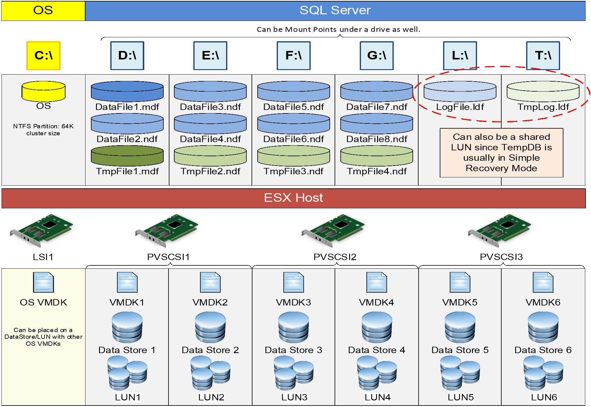
Figure 44 - Sample Disk Presentation for VM Participating in an AG
From a redundancy and availability perspective, imagine that the six datastores are spread over at least two different storage units with logical separation. For example, the two different OS datastores are on different underlying storage, and the respective data and transaction log ones are as well. The goal of availability groups is to not have the underlying storage be a single point of failure, which is the case with FCIs. Some may configure an AG to just use the readable replica functionality, and that would be a perfectly acceptable use of having the data for all replicas on the same storage unit. This may or may not limit how you would use an underlying option such as vSAN or vVols for storage, so you should carefully consider how you plan on using AGs before deploying the VMs for them,
Storage performance is crucial for an AG. Not only do you need to worry about the primary replica which is the read/write copy, but if using synchronous data movement, the secondary replica also needs to have as good, if not better, IOPS to ensure that it does not lag behind. If a secondary replica will be used for other purposes such as read only traffic, on that replica, additional IOPS will be needed for the database participating in the AG as well as TempDB. If these are VMDKs, they should be configured as eagerzeroedthick.
The logic behind the disk representation shown above is beyond simple disk, datastore or LUN redundancy. Separating the disks onto multiple datastores, LUNs and SCSI controllers substantially improves performance for the SQL Server workloads. This is because, in the above sample, IOs from the attached disks are parallelized, ensuring that the aggregate IO from each disk is less likely to saturate a single device along the IO path and is, therefore, unlikely to exceed that device’s queue depth. Queue depth breach leads to IO throttling, which results in sub-optimal query and transaction performance.
4. vSphere Availability Options and SQL Server Interoperability
This next section will cover the availability features available in vSphere and specifically how each one works in conjunction with VMs that have SQL Server running inside.
4.1 Distributed Resource Scheduler
vSphere’s Distributed Resource Scheduler (DRS) is a feature that will reallocate resources based on configured policies. One of DRS’ main benefits is that it can provide load balancing for VMs running in a vSphere cluster. DRS can move (vMotion) a VM to another ESXi host based on host and vSphere cluster resources utilization thresholds set by the vSphere administrator. DRS has a variant (Storage DRS, or SDRS) which would move VMDKs based on IOPS or space utilization of the datastore in a datastore cluster.
DRS monitors resources utilization within a given vSphere Cluster and responds to observed trends by taking defined actions. DRS provides fine-grained configuration and tuning capabilities enabling an Administrators to control both the thresholds at which DRS should take actions, as well as the specific, acceptable actions they expect DRS to take when the defined threshold is breached.
A core requirement for successfully running clustered SQL Server in a vSphere infrastructure is that VMs participating in the WSFC must be configured in such a way that nodes participating in the same WSFC cluster must not run on the same ESXi Host. The mechanism for enforcing this requirement is the DRS rule. DRS is not enabled by default in a vSphere Cluster. When the vSphere Cluster contains WSFC-clustered workloads, enabling DRS becomes a requirement.
When enabled, the default DRS response is set to “manual” as shown in Figure 45. This means that, even if DRS detects unbalanced host resource utilization within a vSphere cluster, DRS will simply report the imbalance and recommend administrative actions to remedy the situation.

Figure 45 - DRS Default Policies and Behavior
For VMs participating in the same WSFC (regardless of whether it’s supporting an FCI or an AG configuration), administrators must configure appropriate DRS rules to ensure that the nodes are always separated onto different ESXi hosts.
4.1.1.1. Configuring DRS Anti-Affinity Rules for Clustered SQL Server Nodes
For detailed information on how to configure the appropriate DRS rule for clustered SQL Server nodes, see Using vSphere DRS Groups and VM-Host Affinity Rules with WSFC Virtual Machines and Create VM-VM Affinity Rules for WSFC Virtual Machines.
The following is a high-level description of the process for configuring DRS anti-affinity rules for a 2-node WSFC.
- In vCenter, click on the name of the vSphere Cluster containing the VMs.
- Click on Configure.
- Ensure that vSphere DRS is turned on. If it is not, just toggle it on as shown in Figure 46.
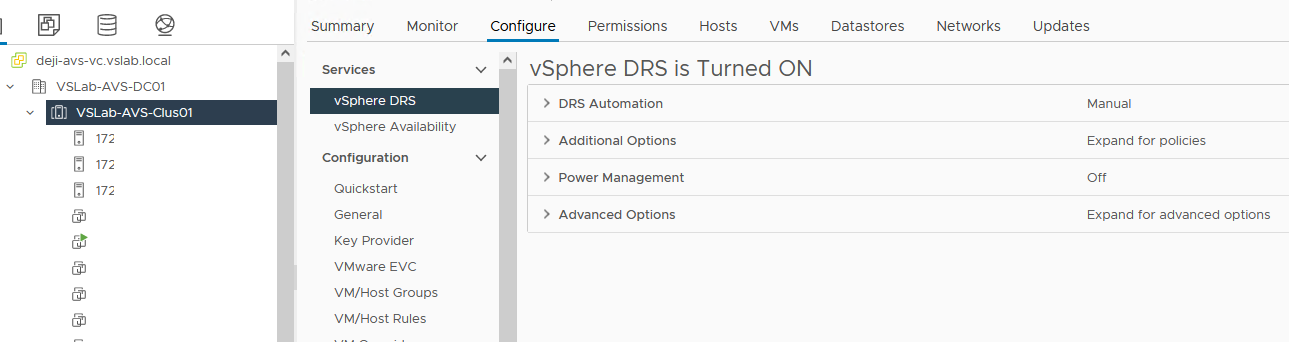
Figure 46 - Verify that DRS is Enabled
- Now, go to the “VM/Host Rules” section and click “Add” as shown in Figure 47.

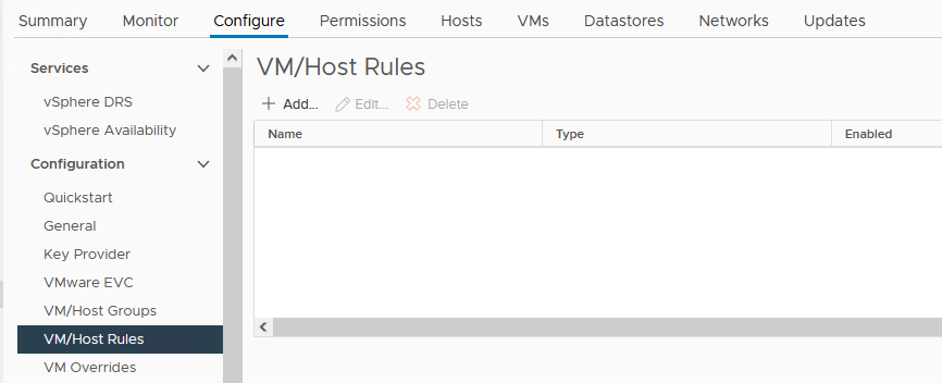
Figure 47 - Creating a DRS VM Rule
- Give the Rule a name, then choose “Separate Virtual Machines” as the rule type, as shown in Figure 48.

Figure 48 - Creating a VM-VM Anti-Affinity Rule
- Click on “Add” on the same screen again and add the VMs that need to be separated. See Figure 49 below. Click “OK” when done.
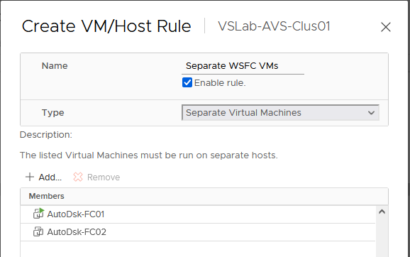
Figure 49 - Applying the Rule to Selected VMs
- Confirm that the rule is enabled, as shown in Figure 50.

Figure 50 - Verify that Rule is Created
From this point on, vSphere DRS will ensure that, to the extent possible, the two VMs are not co-located on the same ESXi Host.
As previously mentioned, the default automation behavior for DRS is “Manual”, meaning that DRS will not re-balance VMs in the vSphere cluster even if it detects unbalanced resource utilization in the cluster. For efficiency and optimal performance, Administrators should consider changing this. DRS uses vMotion to migrate a VM from one host to another if it determines that doing so will benefit the VM and its workload. Substantial improvements in vMotion logics and operations over the years have made vMotion operations very suitable for even the most resource-intensive and sensitive applications in a vSphere environment.
If DRS configured policies and rules seem to cause a noticeable impact on SQL Server’s performance due to an unwanted migration of a VM to another ESXi host, the DBAs and virtualization administrators have the ability to selectively disable DRS for the specific VM, even though DRS is enabled at the vSphere Cluster level for all other VMs in the Cluster. Instead of completely disabling DRS for the VM, this option (called “VM Overrides”) can also be used to fine-tune vSphere’s VM availability automation levels for specific VMs. Here’s a high-level description of how to accomplish this:
- From the DRS configuration screen used in previous sections, click on “VM Overrides”, as shown in Figure 51. Then click “Add”.
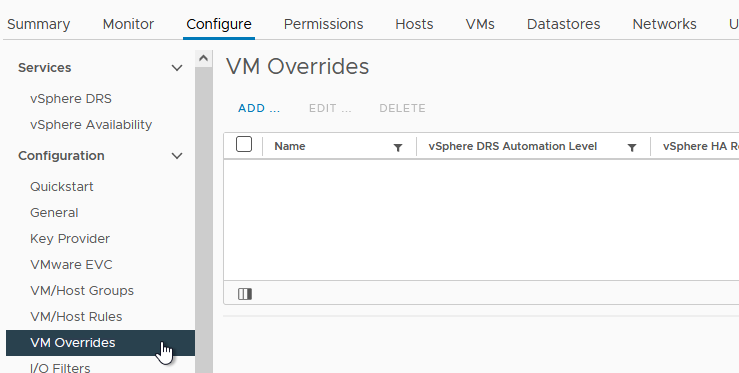
Figure 51 - Create DRS Rules Overrides on for a VM
- Select the VM that will have overrides configured on it and click “Next”. An example is shown in Figure 52.
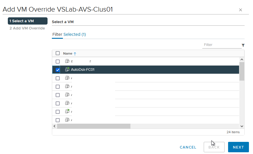
Figure 52 - Apply the Overrides to Desired VM
- Select the desired automation levels for the VM, then click “Finish” as shown in Figure 53.

Figure 53 - Configure Desired VM-Specific Response Rule
If vSphere High Availability is enabled on the luster, the applicable automation settings can also be adjusted through an override.
When enabled, DRS plays a role in determining the initial placement of a VM in a vSphere cluster. It detects the most suitable ESXi Host for the VM and, depending on the automation level, places the VM on that host, or make a recommendation as to placement.
DRS continuously evaluates the health of the cluster and re-evaluates its guidance in response to changing conditions every 5 minutes, although other conditions (for example, a vSphere HA event caused by sudden non-availability of an ESXi Host) may trigger a more immediate response and application of rules.
4.2 vSphere High Availability
vSphere HA provides high availability for virtual machines by pooling the virtual machines and the hosts they reside on into a cluster. Hosts in the cluster are monitored and in the event of a failure, the virtual machines on a failed host are restarted on alternate hosts.
When vSphere HA is enabled in a vSphere cluster, one of the hosts in the cluster is elected as the primary host. All other hosts are each considered a Secondary Host and can become a primary host in the event that the original primary host becomes unavailable. The primary host, among other functions, is responsible for monitoring the state of all VMs and hosts in the cluster. It communicates this knowledge to vCenter and uses this knowledge to determine the appropriate response in the event of a failure of a host in the cluster.
vSphere HA is a very matured technology which has become a staple and core feature of vSphere high availability. When enabled, vSphere HA is responsible for providing continuity for a protected VM if the VM’s host becomes unavailable. vSphere HA is responsible for restarting the impacted VMs previously located on a failed host on a surviving host.
It is important to note that, although it has introspective insights into the health of a VM and its operating system, vSphere HA is not an application-level HA solution. It is not a replacement for WSFC, FCI, or AG. vSphere HA protects a VM, not the application within the VM. As long as a VM’s heartbeat is detectable and determined to be operational, vSphere HA does not intervene, even if the application inside the VM has crashed or become inaccessible for any reason.
vSphere HA compliments (and does not interfere with) WSFC, AG, and FCI. By ensuring that a failed VM (which has failed because, for example, its host has failed) is promptly restarted on another host, vSphere HA reduces the duration of application outage and helps improve an application’s native high availability.
For illustration purposes, consider a scenario in which one of the VMs in a 2-node WSFC-AG configuration is located on Host A. Let’s call this VM “VM-A”. In steady state, everything is ok, operational and available. SQL Server is happy. Let’s say VM-A is currently the primary node for a critical database. Then, in the middle of the night, Host A fails, taking VM-A down with it. Of course, WSFC responds and moves the clustered resources to the second Node and AG does its thing and makes the database accessible within acceptable window.
But the SQL Serve infrastructure is now operating in a degraded, non-highly available, single-node state because VM-A is down. Without vSphere HA, VM-A will remain down until an Administrator intervenes. With vSphere HA, VM-A is immediately powered on another Host while Host A is still down. Within a minute or 2, VM-A has rejoined the WSFC cluster and HA stability is restored. Of course, it is no longer the primary node at that point (unless auto-failback has been configured in WSFC), but this is immaterial from a high availability perspective.
Some Customers have inquired about the feasibility of using vSphere HA to provide “good enough” high availability for their SQL Server workloads. This inquiry is primarily driven by cost considerations (the cost of extra licenses requires by the extra node, WSFC and SQL clustering, additional storage (for AG), etc. VMware’s position is that this choice should be informed primarily by Customers’ and Business Owners’ SLA and resource availability expectations. If a short interruption of service and access is acceptable, then vSphere HA provides enough protection and availability for SQL Server, with the caveat that someone who is responsible for SQL Server must check that the databases are OK after coming up
It is important to also stress that if using vSphere HA without native Windows/SQL Server HA options, and the SQL Server VM becomes unavailable, applications and end users would notice that SQL Server was unavailable while the VM is being brought online on another host. One difference from SQL Server’s built in availability features is that an application accessing an FCI or AG can be made resilient and/or cluster-aware if coded properly; there is no equivalent API for vSphere HA. At that point, it would be recommended that before any connections were allowed to use SQL Server, the DBAs ensures that the instance and its databases are fine. vSphere HA is a stop and a start as if a physical host was used, so SQL Server will go through its standard recovery mechanisms.
4.3 vSphere Fault Tolerance
vSphere Fault Tolerance (FT) creates an identical clone of a VM and keeps it up-to-date continuously. This means that if the ESXi host of the original VM somehow encounters a problem, the FT copy can replace it only if what is running inside the VM is not broken, such as corrupted installation of SQL Server or Windows Server. It is a 1:1 ratio from the primary to the secondary VM, meaning that, with FT, you can only have a single copy of a source VM.
If a failover occurs and the secondary VM becomes the new Primary VM, a new secondary VM will be automatically deployed for its replacement on another ESXi Host. The primary and secondary FT VMs cannot be on the same host, so a minimum of three ESXi Hosts will be needed in the vSphere cluster for full protection. Only one copy of a FT VM is accessible at any given time.
VMware Fault Tolerance has strict limitations on the VM’s compute resource capacity, and this might make it unsuitable for large SQL Server instances. Table 3 below shows the maximum supported compute resource allocation for VMs participating in Fault Tolerance:
Table 3. vSphere Fault Tolerance Maximums
|
Config Maximum |
vSphere 6.7, 7.0, 8.0 |
vSphere 6.5 |
|
Max CPU Per VM |
8 |
4 |
|
Max RAM Per VM |
128 GB |
64 GB |
|
Max Virtual Disk Per VM |
16 |
16 |
|
Max Disk Size Per VM |
2 TB |
2 TB |
|
Max FT VMs Per Host |
4 |
4 |
|
Max FT CPU Per Host |
8 |
8 |
It is also important to note that, because the FT protects at a VM layer, the secondary VM is an exact copy of the primary VM. This means that any OS or application defects on the primary VM is replicated intact to the Secondary VM. VMware FT is not an exact replacement for application-level HA.
VMware FT is not supported with clustered configurations of SQL Server.
4.4 vSphere vMotion
vSphere vMotion gives a VM the ability to move from host to host, network to network, storage to storage, and datacenter to datacenter while the VM remains online and continues to provide services. This means that if SQL Server is running in the guest, there is no downtime – applications and end users can still use it during the migration with no downtime and minimal impact to performance. For mission-critical workloads that need to be rehosted, this is one of the biggest benefits of vMotion. vMotion in this manner also can enable seamless hardware migrations for vSphere architectures with no downtime.
See vMotion support for WSFC for recommended configuration information and considerations for vMotion support considerations for SQL Server clustering. Additional information for architecting your VMware infrastructure to optimally support the use of vMotion for production, enterprise-class SQL Server instances are available in Architecting Microsoft SQL Server on VMware vSphere.
vMotion is a standard feature in the vSphere infrastructure, so there is no VM-specific configuration required for the VM to be vMotion-eligible or vMotion-compatible. Improvements in vMotion make it suitable and non-disruptive for even the most demanding SQL Server instances in the enterprise.
One common challenge when performing a vMotion operation on a VM that is participating in a clustered configuration of SQL Server is the possibility of temporary service outage. It is, therefore, useful to describe the conditions that trigger this outage.
When a vMotion operation is invoked (manually by an Administrator or automatically by DRS), vSphere copies the VM’s state from its current host to a target host. This copy operation is iterative and incremental. The duration of the copy operation is dictated by the following factors (among others):
- The size of the compute resources allocated to the VM
- The size of available compute resource on the target host
- The frequency of change in the VM’s guest operating system
- The network bandwidth and throughput
When vSphere has copied enough of the VM’s state and determined that what is left can be copied over in one transaction, vMotion invoked the Windows Volume Shadow Service (VSS) and requests that it freezes the VM so that vMotion can perform a last copy. When Windows freezes the VM, all operations inside Windows is suspended. During this suspended state, the VM is unable to communicate with its WSFC peer – it is unable to send or receive cluster heartbeat probes. In earlier versions of Windows, threshold for missed heartbeat before WSFC declares a node to be unavailable is 5 seconds. This means that, if the VM remains in this suspended state for longer than 5 minutes, WSFC will trigger a resource failover to another node in the cluster.
This is why unintended resource failover incidents happen on clustered SQL Server Nodes during failover. This behavior is neither peculiar nor unique to virtualized SQL Server instances. It happens the same way for SQL Server instances on physical server. The trigger is the invocation of VSS by any operation or process which needs to take a point-in-time snapshot of Windows Server.
In later versions of Windows Server, this threshold has been increased to 10 seconds (for cluster nodes located in the same subnet) and 20 seconds (for cluster nodes located in the different network segments). In a properly-configured vSphere infrastructure (for example, where adequate compute resources are available, 10G network cards are in use, multi-NIC vMotion Portgroups have been configured, the underlying network infrastructure has jumbo frames enabled, and others), vMotion’s last copy operation should be completed well before reaching the point of triggering WSFC’s resource failover behavior.
When an affinity/anti-affinity rule is employed with DRS/SDRS, it can be violated by a manual vMotion. Because the DRS/SDRS rules are run periodically, this problem should correct itself and the VMs that should be together or apart depending on the rule will be placed where they should be across the vSphere hosts.
From a SQL Server perspective, one of the biggest benefits of vMotion is that everything that is in memory – such as execution plans and recently used data in cache – remains there. Therefore, performance for SQL Server instances and databases will remain the same instead of hitting the proverbial reset button in a traditional failover. There may be a short impact during the host switching, but applications should not really notice.
4.5 Site Recovery Manager
vSphere Site Recovery Manager (SRM) is an orchestration solution that enables disaster recovery and avoidance, as well as site migration. Disaster recovery allows you to come online elsewhere if your primary data center was experiencing a major downtime event. SRM requires the use of either block-level replication for storage or vSphere Replication. Either can be used, or it is possible to mix them as well to synchronize VMs between sites.
One of the core value-add of SRM as a Business Continuity and Disaster Recovery (BCDR) solution is that it uniquely enables Administrators, Business Owners, Auditors, and authorized Stakeholders to perform simulated BCDR scenarios without any negative impact or stress on the Production environment. Customers can failover an entire SQL Server farm and all its upstream and downstream dependencies into an SRM “Bubble Network” without interrupting continuous access to the live environment. Customers can use this option to continuously verify, validate, and refine their protection and recovery plans, on-demand.
Programmable and configurable recovery automation is a very essential for an optimal BCDR Plan. A BCDR solution should be able to provide assured workflow predictability. Manual administrative tasks are prone to human errors, especially in the middle of a catastrophic disaster in an enterprise. Here is a short highlight of some features and capabilities of SRM which minimizes the number of manual administrative tasks required recover and restore services after a disaster event:
- IP reconfiguration – A DR site is usually geographically separate from the protected production site. Without expensive network stretching technologies, the IP addresses in both sites are usually different. This means that if you recover a protected VM with an IP address of “a.b.c.d” to a DR site (where the subnet range is, say, e.f.g.x”), the recovered VM will not be fully recovered nor able to provide its hosted services. SRM solves this problem by providing a mechanism to preconfigure the target IP address that a recovered VM should have at the DR site upon recovery.
- Recovery (machine and service) dependencies – SQL Server instances are usually parts of multi-tiered applications constructs. They usually provide services leveraged by other Servers (e.g., Web Servers) and they, in turn, depend on things like ADDS, DNS, etc. In a DR event, the order of recovering these tiered workloads is very important. If you recover an AD-joined SQL Server VM when the Domain Service is still unavailable, the SQL Server will not be fully recovered. SRM solves this problem by enabling an Administrator to preconfigure the order in which all protected VMs are recovered.
- Script execution – Restoring service continuity in a DR event is usually much more than just bringing up all the Servers and declaring success. There are usually some processes and other administrative tasks which might be required for service restoration.
For example, WSFCs AGs and FCIs have additional IP addresses and DNS records for performing their functions. These IP addresses are different from the IP address configured on the NIC in Windows Server (TCP/IP). While SRM can easily change the Windows IP address as explained in section 1 above, it does not change the cluster and listener IP addresses. For this and other needs, SRM provides an easy mechanism for Administrators to invoke scripts to perform these non-standard post-recovery tasks.
An exhaustive and comprehensive documentation of how to protect and recover a production Microsoft SQL Server infrastructure in its entirety with VMware Site Recovery Manager is available in Protecting and Recovering Mission-Critical Applications in a VMware Hybrid Cloud with Site Recovery Manager
Of importance in this document is the fact that SRM supports WSFC, AG, FCI, and standalone SQL Server instances without any limitations.
5. Determining Availability Architecture for SQL Server and vSphere
Architecting the availability strategy for your SQL Server deployments is based on requirements. The following are some common questions that can assist in the process:
· What are you trying to protect?
· What are your limitations – skills of the team, resources, versions/editions of Windows Server, SQL Server, etc.?
· What does the application using SQL Server support?
· What are your documented recovery point and recovery time objectives?
There is no one-size-fits-all solution when it comes to ensuring that a VM or set of VMs is highly available. The key difference in the vSphere features versus what is provided by SQL Server is that the vSphere features are designed to protect the VM, whereas the SQL Server features (or ones that hook into the proper SQL Server APIs, such as third party backup utilities) protect the instance or data and provide point-in-time recovery of the data with the use of things like AGs or transaction log backups.
Control plays into this decision – do you want the DBAs to manage the availability story for SQL Server, or the non-SQL Server administrators? The answer is that everyone needs to work together to craft a solution that meets the requirements. Since the primary responsibility for an instance of SQL Server lies with the DBAs in most organizations, they should be heavily involved in the decision of what features should be used.
For mission critical, Tier 1 applications, a combination of SQL Server native HA features (such as FCI, AG) with the proven ease, resilience and reliability of vSphere HA and DRS provide the most robust and optimal high availability solution.
As a counterpoint, for less critical, Tier 3 VMs hosting SQL Server instances and databases which may have had no availability story prior to virtualization, it may be excessive to deploy an AG or FCI, but using something like FT or even just vSphere HA not only gives that VM protection where there was none, but it should exceed expectations where none existed.
The vSphere solution that is deployed should be the result of discussions with all groups involved. At the end of the day, it is usually the DBAs who will ultimately be responsible for the maintenance, performance, and availability of SQL Server instances and databases running in the VMs. Clear lines of delineation for administration should be discussed, and DBAs – or a subset of them – should be given read only rights in vCenter.
If you have more than a handful of SQL Server deployments that are or will be virtualized, you should consider having dedicated vSphere clusters or ESXi hosts for them. This may reduce your licensing costs instead of having to account for each VM individually or license an AG or FCI solution as if each VM was like it was on physical hardware. Reducing cost is often one of the drivers for virtualizing SQL Server, so as part of an overall mission critical strategy, licensing is a key component.
6. Summary
Mission critical deployments of SQL Server are commonplace now under vSphere. One of the most important tasks is to ensure that the VMs and the workloads running in them have the availability that is required by the business. Whether you use the native SQL Server and Windows Server features, the vSphere features, or a combination of what Microsoft provides with what VMware provides, you can create resilient deployments. The SQL Server availability features and the ones in vSphere can be used exclusively or complement each other; things do not need to be all one or the other. Using both, you can create a best-of-breed solution that will not only provide the reliability that you require, but using vSphere, an agile, robust deployment architecture that will benefit both DBAs and system administrators alike.
7. Acknowledgement and Credits
Dèjì Akọ́mọláfẹ́ – Staff Solution Architect and Practice Lead (Microsoft Business Critical Applications)
Mark Xu - Sr. Technical Marketing Architect
Catherine Xu - Group Manager, Workload Technical Marketing
Allan Hirt (Author and Founder of SQLHA)
This document was originally commissioned by VMware, and authored by Allan Hirt of SQLHA, LLC who is also a Microsoft Cloud and Datacenter Management MVP and Data Platform MVP as well as a VMware vExpert.
All applicable claims of intellectual properties are hereby acknowledged to the extent required and permissible.
8. Related Documents and Links
General Information
· Architecting Microsoft SQL Server on VMware vSphere
· Protecting and Recovering Mission-Critical Applications VMware Hybrid Cloud with SRM
· Optimizing BCDR Plans in SRM: Leaving Unnecessary Disk and Data Behind
· vSphere Resource Management - VMware vSphere 8.0
· vSphere Resource Management - VMware vSphere 7.0
· Performance Best Practices for VMware vSphere 8.0
· Performance Best Practices for VMware vSphere 7.0
· Performance Best Practices for VMware vSphere 6.7 Update 2
· Performance Best Practices for VMware vSphere 6.0
· Setup for Windows Server Failover Clustering - VMware vSphere 7.0
· Setup for Failover Clustering and Microsoft Cluster Service - VMware vSphere 6.7
· Setup for Failover Clustering and Microsoft Cluster Service - VMware vSphere 6.5
· Microsoft Cluster Service (MSCS) support on ESXi
· Once More With Feeling: Stop Using Active/Passive and Active/Active
· AlwaysOn is the New Active/Passive and Active/Active
· Dear Microsoft: I Love You, But You’re Driving Me Batty
SQL Server and Windows Server Licensing
· SQL Server 2022 Licensing Datasheet
· SQL Server 2019 Licensing Datasheet
· SQL_Server_2017_Licensing_Datasheet
· Windows Server Licensing Guide
· Windows Server 2019 licensing Datasheet
· Windows Server 2016 Licensing Datasheet
VMware vSphere Configuration Maximums
· vSphere 8.0 Configuration Limits
· vSphere 7.0 Configuration Limits
· vSphere 6.7 Configuration Limits