
Deployment Guide: Modernize Your IT Infrastructure with Hybrid Cloud Solutions from Lenovo and VMware
Introduction
Overview
This deployment guide will walk the customer through deploying a Hybrid Cloud using VMware Cloud Foundation (VCF) on Lenovo ThinkAgile VX servers. It offers a turnkey hybrid cloud solution, combining Lenovo hardware, VMware software with Lenovo XClarity integration, and Azure VMware Solution (AVS) to provide customers with an automated hyperconverged infrastructure with easy management.
Audience
This deployment guide is intended for IT professionals with varying levels of VMware expertise who are responsible for deploying or managing VMware-based Software-Defined Datacenters (SDDCs) in both on-premises deployments and hybrid cloud architecture. The audience will benefit from having a base understanding of the VMware SDDC stack, including vCenter, ESXi, vSAN, NSX, as well as familiarity with deploying cloud components in Microsoft Azure. While some exposure to Lenovo's tools such as XClarity Controller, XClarity Administrator, or XClarity Integrator can be helpful, it is not a prerequisite for understanding and utilizing this reference architecture document.
Prerequisites
There are several requirements, including software packages, tools, network configuration, and information gathering the customer will need prior to starting the deployment.
VMware components
Below are the required VMware components which can be downloaded from VMware Customer Connect:
- VMware Cloud Foundation
- VMware Cloud Builder Version 4.5.1 – build number 21682411
- Cloud Builder Deployment Parameter Guide
- VMware vSphere Hypervisor (ESXi)
- VMware vSphere Hypervisor (ESXi) Offline Bundle version 7.0u3L – build number 21424296
- Ensure download of the offline bundle .ZIP file, not the .ISO file.
- Lenovo OEM Addon for ESXi
- If the OEM Customized Addon file doesn’t exist for 7.0u3L, select a previous ESXi version to locate the Lenovo Addon for ESXi 7.0 U3.
- VMware vSphere Hypervisor (ESXi) Offline Bundle version 7.0u3L – build number 21424296
- VMware PowerCLI
- Image Builder is included with PowerCLI, but additional components are required
- Powershell 5.x (not Powershell Core or 7.x)
- Python 3.7.9
- Newer versions are available but may cause Image Builder to not run properly
- Image Builder is included with PowerCLI, but additional components are required
Lenovo Components
- Lenovo XClarity Administrator (LXCA)
- Download the latest Lenovo XClarity Administrator Virtual Appliance Full Image - OVA
- Download the OVA and accompanying MD5 or SHA256 file to verify integrity.
- At the time of this writing, version 4.0.0 is latest, requiring Lenovo XClarity Administrator GA Fix 4.0.3
- Download all files associated with the GA Fix
- Download the latest Lenovo XClarity Administrator Virtual Appliance Full Image - OVA
- Lenovo XClarity Integrator for VMware vCenter (LXCI)
- Download the full image as well as any fix patches
Network Configuration
Before proceeding, verify the following network requirements are met.
- Two top of rack (ToR) switches designated as Path A and Path B
- It is possible to deploy this configuration with a single top of rack switch, but not recommended.
- Jumbo frames with an MTU size of 9000 is recommended for all interfaces, VLANs, and uplinks
- Jumbo frames must be configured for the entire data path end-to-end, including any routers where NSX-encapsulated traffic may traverse.
- The following VLANs must be configured prior to deployment for a consolidated architecture:
- Management – Jumbo frames not required but recommended for consistency.
- vMotion – Jumbo frames required.
- vSAN – Jumbo frames required.
- NSX host overlay – Jumbo frames required.
- NSX edge overlay – Jumbo frames required.
- Uplink A – Jumbo frames required.
- Uplink B – Jumbo frames required.
- VM workload(s) – Jumbo frames not required but recommended for consistency.
- Additional required VLANs for a standard architecture:
- Workload domain NSX host overlay – Jumbo frames required.
- Workload domain NSX edge overlay – Jumbo frames required.
- Server physical cabling
- Server ports cabled for HA between Path A and Path B
- Minimum of dual port network adapters split between Path A and Path B
- XClarity Controller (XCC) cabled & configured
- Ensure proper firewall rules are in place to allow communication from LXCA & LXCI to the XCC:
- Server ports cabled for HA between Path A and Path B
- DNS
- Ensure that forward and reverse records exist for all components being deployed by VCF, as well as the Lenovo components:
- SDDC Manager
- vCenter
- all ESXi host management IPs
- Three NSX Managers and one management virtual IP (VIP)
- For simplicity, supply the NSX manager DNS name for the VIP and append a/b/c for the three virtual appliances
- NSX Edge VMs
- Management interface for each edge VM, IP assigned out of the management network
- Lenovo XClarity Administrator (LXCA)
- Lenovo XClarity Integrator for VMware vCenter (LXCI)
- Ensure that forward and reverse records exist for all components being deployed by VCF, as well as the Lenovo components:
- BGP configuration – optional but recommended
- Each Tier-0 gateway will have four interfaces.
- two on Uplink A VLAN and two on Uplink B VLAN.
- Each Services Router (SR) component will have two interfaces, one per uplink VLAN.
- The BGP neighbors on the ToR will need to be configured for all four source IP addresses.
- The keep alive timer should be configured for four (4) seconds
- The hold down timer should be configured for 12 seconds
- These timers are pre-configured when deploying an NSX Edge cluster through SDDC Manager
- The deployment will fail if the timers do not match.
- If there’s a requirement for different timers, such as 10/30, users can edit the timers on the Tier-0 gateway when deployment fails, retry peering then retry the task to complete the edge cluster deployment.
- Each Tier-0 gateway will have four interfaces.
Installation Steps
The following steps are to be considered a framework for the deployment of a VMware Hybrid Cloud solution on Lenovo ThinkAgile servers. While the guide may be a complete installation walkthrough, there may be some additional steps needed for each individual environment.
Assumptions
For the purposes of this guide, it is assumed that all hardware is physically racked, cabled, and powered on. All Out-Of-Band (OOB) management endpoints are configured and accessible from the network.
For the ThinkSystem DM5000H, please see the Hardware Installation and Maintenance Guide: https://thinksystem.lenovofiles.com/storage/help/topic/dm5000f-dm5000h-dm3000h-himg/Lenovo_DM3000x_and_DM5000x_Hardware_Installation_and_Maintenance_Guide.pdf
Step 1 – Configure ToR Switches
The VLANs outlined above need to be configured on the switches. The CIDRs, VLAN IDs, and gateway IPs will be used in the next step. For consistency, building all networks as a /24 CIDR with an MTU of 9000 will result in less human error.
Step 2 – Complete Deployment Parameter Workbook
The Deployment Parameter Workbook assists in gathering all requisite information for the successful deployment of the VCF management domain. For detailed information regarding the Deployment Parameter Workbook, see here: https://docs.vmware.com/en/VMware-Cloud-Foundation/4.5/vcf-deploy/GUID-08E5E911-7B4B-4E1C-AE9B-68C90124D1B9.html
- Credentials tab
- ESXi, vCenter, and SDDC Manager policy: Each password must be at least eight (8) characters up to 20 with at least one uppercase, lowercase, number, and a special character (!@#$%^?).
- Configure all ESXi installations with the password supplied in this workbook.
- NSX-T Data Center requires at least 12 characters in addition to the previous password requirements, must not be a dictionary word, nor have three (3) of the same consecutive characters.
- Hosts and Networks tab
- Management Domain Networks
- Provide VLAN ID, CIDR subnet, gateway IP, and MTU for each of the three networks that were created in the ToR switch configuration. Enter VLAN ID “0” for native VLAN. Port groups should be named in such a manner as to differentiate the management domain, cluster, and use for each port group. Example: m01-cl01-vds01-pg-mgmt conveys that it is the management port group for the first cluster in the management domain.
- Management Domain ESXi Hosts
- Provide the hostname and IP address for the first four nodes of the management domain. Do not supply the FQDN, the DNS zone will be provided at a later step. Provide the IP address pools for vMotion and vSAN. Supply a sufficient pool size for vMotion and vSAN to accommodate any additional nodes that may be deployed following the initial four nodes of the management domain.
- Virtual Networking
- Leave vSphere Standard Switch (VSS) Name as vSwitch0, as that is the default VSS name of newly deployed ESXi hosts.
- Provide a descriptive name for the Primary vSphere Distributed Switch (VDS), as well as the physical NICs that will be assigned to the VDS, either two or four NICs, and set MTU to 9000. Profile-1 assigns all physical NICs to the VDS and can have two or four NICs. Profile-2 separates vSAN traffic on to a secondary VDS and requires four NICs split evenly between the two VDSs. Profile-3 separates NSX overlay traffic on to a secondary VDS and requires four NICs split evenly between the two VDSs. Specify the desired physical NICs for each VDS. It is recommended that each VDS has physical NICs cabled to different paths, Path A and Path B for instance.
- Security Thumbprints
- Once the four nodes of the management cluster are built, it is possible to supply the SSH RSA key fingerprint as well as SSL thumbprint for each node in the cluster. Alternatively, it is easier to select No for Validate Thumbprints.
- NSX-T Host Overlay Network and Static IP Pool
- Provide the VLAN ID that was created in the ToR switch configuration for the NSX host overlay network.
- To avoid the requirement of a DHCP server, set Configure NSX-T Host Overlay Using a Static IP Pool to Yes
- Provide a pool name & description, the gateway IP and subnet in CIDR notation created in the ToR switch configuration, and a pool size large enough to accommodate all NSX interfaces in the environment. For example, if each node in an eight (8) node cluster has two vmnics assigned to the VDS for NSX Host Overlay, then the pool will need to be a minimum of 16 addresses. It is recommended to create a pool large enough to accommodate future expansion of the cluster.
- Management Domain Networks
- Deploy Parameters tab
- Existing Infrastructure Details
- Provide two DNS servers and at least one NTP server by either IP or FQDN. Enter “n/a” to ignore validation in the workbook. These values will be used for all components deployed by VCF and should also be used when manually deploying any ESXi nodes or Lenovo components for consistency.
- Enter the DNS zone that will be appended to hostnames to form the FQDN.
- It is recommended to Enable the Customer Experience Improvement Program, CEIP.
- License Keys
- This deployment guide will use individual license keys for the components deployed by VCF.
- Supply the appropriate keys for the license level required for the deployment. For instance, VCF Advanced Edition requires NSX-T Advanced and vSAN Advanced license keys.
- vSphere Infrastructure
- Supply the desired hostname and sizes for the vCenter appliance, as well as an IP address from the management network.
- Supply the desired virtual Datacenter and Cluster names.
- Leave Cluster EVC Setting as n/a unless otherwise required for your environment
- NOTE: For live migration of workloads to Azure AVS, verify the CPU of the AVS cluster. As of this writing (August 2023) the “av36” host sku in Azure is Intel Skylake. For more information on selecting the correct EVC mode, see this KB article: https://kb.vmware.com/s/article/1003212
- Select the VCF architecture to be deployed:
- Consolidated – Select this if the environment will be a single cluster with workload VMs residing on the same physical cluster as the SDDC components.
- Standard – Select this if the environment will consist of additional workload clusters not residing in the same management vCenter, also known as VI Workload Domains.
- If deploying a Consolidated Architecture, supply descriptive resource pool names to provide a level of separation within the consolidated deployment.
- Supply the desired vSAN datastore name, and whether to enable deduplication and compression or not.
- NSX-T Data Center
- Supply the desired NSX VIP and hostname, as well as the three virtual appliance hostnames and IPs, and select the desired appliance size.
- SDDC Manager
- Supply the desired hostname and IP address for the SDDC Manager.
- Supply the desired network pool name. This network pool is where the vSAN and vMotion IP pools will reside that were provided in the Hosts and Networks tab.
- Supply the desired VCF Management Domain Name. This is an identifying name for the SDDC manager when deploying additional management domains.
- Existing Infrastructure Details
Step 3 – Create custom ESXi ISO
The following steps walk through installing the necessary components needed to create a customized ESXi installation ISO consisting of the Lenovo Addons. Proceeding with a non-customized ESXi installation may result in undetected hardware, as the necessary drivers may not be included.
- Install PowerCLI
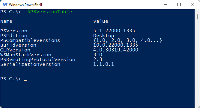
- Verify the proper version of Powershell by opening a Powershell terminal and typing $PSVersionTable
- Image Builder works with Powershell up to 5.x and doesn’t work with later releases known as Powershell Core, which may be version 6.x or 7.x. If a newer version is installed, run powershell.exe to open a Powershell 5.x version. Rerun $PSVersionTable to verify the Powershell version.
- Verify the proper version of Powershell by opening a Powershell terminal and typing $PSVersionTable
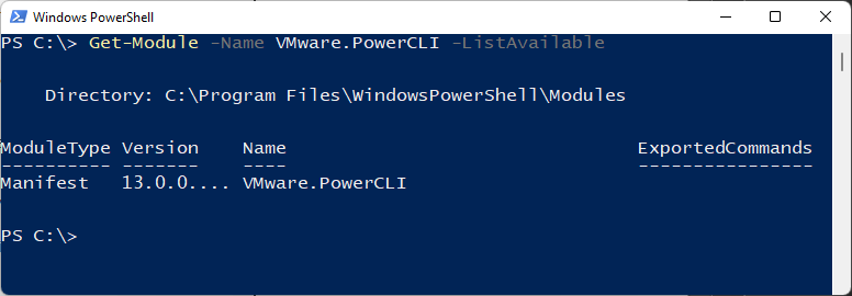
- Install the latest version of PowerCLI by running Install-Module VMware.PowerCLI -Scope CurrentUser
- You can verify PowerCLI installation by running Get-Module -Name VMware.PowerCLI -ListAvailable
- Install Python & PIP
- Download & install Python 3.7.9 from the following link: https://www.python.org/downloads/release/python-379/
- You will need to right-click and select Run As Administrator when installing Python 3.7.9.
- Take note of where Python is installed, the path needs to be entered in a later step.
- It is typically installed in: C:\Users\<User>\AppData\Local\Programs\Python\Python37
- Install PIP by running the following command:
- C:\Users\<User>\AppData\Local\Programs\Python\Python37\python.exe -m pip install --upgrade pip
- Alternatively, you can save this file as get-pip.py and run the command below: https://bootstrap.pypa.io/get-pip.py
-
C:\Users\<User>\AppData\Local\Programs\Python\Python37\python.exe get-pip.py
-
- Install required packages via PIP
-
C:\Users\<User>\AppData\Local\Programs\Python\Python37\Scripts\pip3.7.exe install six psutil lxml pyopenssl
-
- Download & install Python 3.7.9 from the following link: https://www.python.org/downloads/release/python-379/
- Set the PowerCLI python path
-
Set-PowerCLIConfiguration -PythonPath C:\Users\<User>\AppData\Local\Programs\Python\Python37\python.exe -Scope User
-
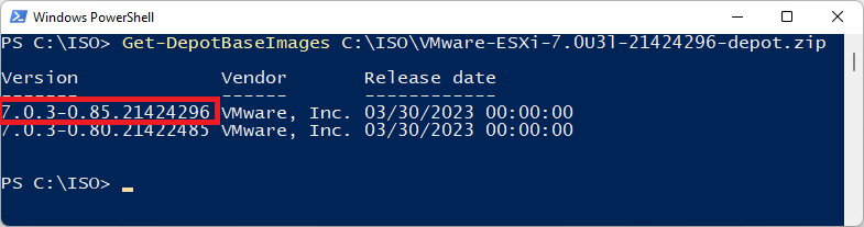
- Inspect the base image version in the offline bundle downloaded in the prerequisites and take note of the version:
-
Get-DepotBaseImages C:\ISO\VMware-ESXi-7.0U3l-21424296-depot.zip- There may be more than one base image version in the depot, be sure to use build number 21424296
-
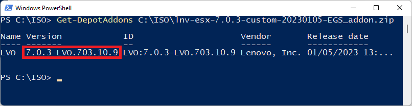
- Inspect the Lenovo addon package and take note of the version
-
Get-DepotAddons C:\ISO\lnv-esx-7.0.3-custom-20230105-EGS_addon.zip
-
- Create a software specification, save it as a json file. Below is an example you can copy & paste:
{
"base_image": {
"version": "7.0.3-0.85.21424296"
},
"add_on": {
"name": "LVO",
"version": "7.0.3-LVO.703.10.9"
}
}
- Generate the new customized ESXi installation ISO with Lenovo addons
-
New-IsoImage -Depots "C:\ISO\VMware-ESXi-7.0U3l-21424296-depot.zip","C:\ISO\lnv-esx-7.0.3-custom-20230105-EGS_addon.zip" -SoftwareSpec "C:\ISO\lenovo-spec.json" -Destination "C:\ISO\Lenovo-ESXi-7.0u3L-21424296.iso"
-
Step 4 – Install ESXi on the first server
Interactively installing ESXi on the first server in the cluster will allow the installation of Lenovo XClarity Administrator (LXCA) to facilitate the automated deployment of all remaining servers.
- Launch the XCC web interface for the first server of the cluster and launch the Remote Console.
- Mounting virtual media is done through the Remote Console
- Click the Media button to launch the virtual media interface.
- Click the Activate button to enable mounting of virtual media.
- Ensure ISO Image is selected and click Browse, locate the customized ISO created in the previous section, then click Mount all local media
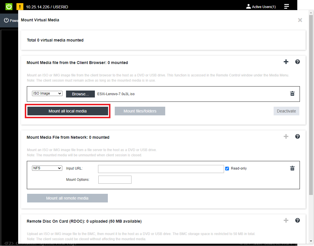
- A green checkmark will indicate the virtual media is mounted successfully.
- Scroll down, expand Select one virtual media to boot on next restart, select the ISO Image from the drop down, set behavior to Restart server immediately, click OK, then Apply
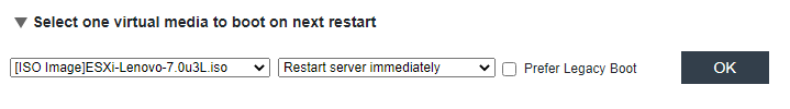
- After clicking Apply, click Close and watch the console to verify the server is rebooting from the custom installation ISO:
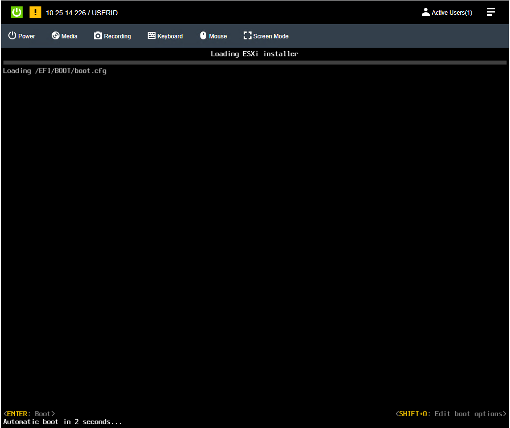
- Follow the prompts of the Interactive ESXi installer, providing the ESXi root password created in the Deployment Parameter Workbook.
- Click here for installation instructions: https://docs.vmware.com/en/VMware-vSphere/7.0/com.vmware.esxi.install.doc/GUID-6FFA928F-7F7D-4B1A-B05C-777279233A77.html
- Once the installation is complete, the system prompts to remove the installation media before rebooting.
- Click the Media button, click Unmount to the right of the ISO image, OK to confirm, then scroll down and click Close.
- Hit Enter in the remove console to initiate the reboot.
- After ESXi has rebooted, the network will need to be configured to match the information provided in the Deployment Parameter Workbook.
- Hit F2, type in the password provided during installation, and navigate to Configure Management Network.
- If a VLAN ID other than zero (“0”) was supplied in the Deployment Parameter Workbook, enter it under VLAN ID, otherwise leave it blank to use the switch port’s native VLAN.
- Navigate to IPv4 Configuration and specify the static IP address, subnet mask, and default gateway supplied in the Deployment Parameter Workbook.
- Navigate to DNS Configuration, provide the DNS servers from the Deployment Parameter Workbook, as well as the Hostname of the server (Hostname only, not FQDN)
- Navigate to Custom DNS Suffixes and provide the DNS Zone from the Deployment Parameter Workbook.
- Hit escape to exit the Configure Management Network menu, then hit Y to apply the changes & restart the management network.
- Verify you can reach the Host UI of the server by navigating to it’s FQDN in a web browser.
- Hit F2, type in the password provided during installation, and navigate to Configure Management Network.
- Configuration requirements for VCF (these steps will be automated using an unattend file while deploying ESXi through LXCA)
- Enable SSH
- Log into the Host UI and click Manage under Host
- Select the Services on the top of the right pane and locate TSM-SSH
- With TSM-SSH selected, click the Actions button, navigate to Policy, and select “Start and stop with host”
- Then click Start. A green triangle with “Running” should appear in the row signifying the service is now running.
- Log into the Host UI and click Manage under Host
- Configure NTP
- Click the System tab at the top left of the right pane, then select Time & Date
- Click Edit NTP Settings, then select the radio button for “Use Network Time Protocol (enable NTP client).
- Change the NTP service startup policy to “Start and stop with the host”
- Provide the NTP server specified in the Deployment Parameter Workbook, then click Save
- Refresh the page and verify current date and time and NTP service status is Running.
- Click the System tab at the top left of the right pane, then select Time & Date
- Regenerate certificates
- By default, the self-signed certificates have localhost.localdomain as the CN, but VCF requires the CN match the host name of the server.
- SSH into the server and type the following commands
- /sbin/generate-certificates
- /etc/init.d/hostd restart
- /etc/init.d/vpxa restart
- Verify the certificate now matches the hostname by refreshing the Host UI and viewing the new certificate’s CN.
- By default, the self-signed certificates have localhost.localdomain as the CN, but VCF requires the CN match the host name of the server.
- Enable SSH
Step 5 – Deploy Lenovo XClarity Administrator
- Log into the Host UI, click Virtual Machines in the left navigation pane and click Create / Register VM
- In the New virtual machine wizard, select “Deploy a virtual machine from an OVF or OVA file” then click Next.
- Provide a name for the LXCA VM as it will be viewed in the Hosts & VMs view.
- Click the light blue box and navigate to the Lenovo XClarity Administrator OVA downloaded during the prerequisite section.
- Select datastore1 and click Next.
- Leave Network mappings as “VM Network”, select the appropriate Deployment type that matches the size of the environment. Select the disk provisioning type desired.
- Uncheck “Power on automatically” and click Next.
- At Additional settings, click Next, the network configuration will be supplied during boot.
- At Ready to complete, click Finish.
- After the import completes, navigate to the VM and click the Start button inside the console window to power on the VM and open the web console.
- Watch the console for the network configuration prompt, you have 2.5 minutes to make a selection before it continues.
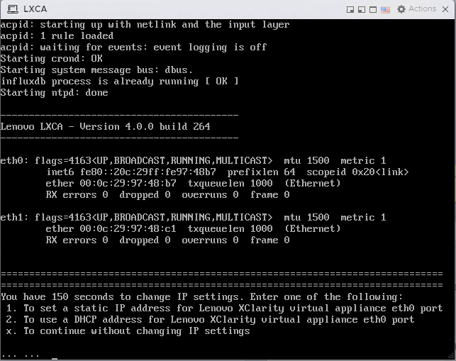
- Press 1 and hit Enter to set a static IP
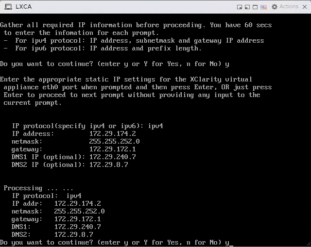
- Follow the prompts to enter the desired network configuration, then hit Y and enter to confirm:
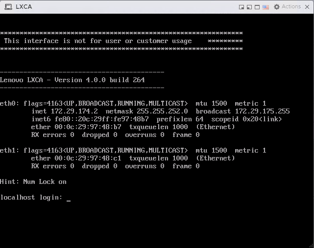
- It may take a few minutes for the appliance to reboot and set the configuration. This screen indicates when the initially deployment is completed:
- Navigate to the web interface for the LXCA appliance to start the configuration wizard: https://<ipaddress>/
- Click below for the steps to configure LXCA for the first time: https://sysmgt.lenovofiles.com/help/topic/com.lenovo.lxca.doc/setup_configurelxca.html?cp=1_5_0_3
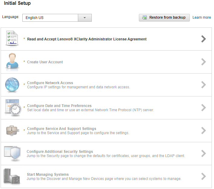
- Follow the setup wizard to the Configure Network Access section
- Leave “Select the interface for the operating system image management and deployment” set to None.
- Click Return to initial setup. Do not change any network configuration yet.
- Continue through the initial setup wizard.
- Click Start Managing Systems, then select “No, don’t include Demo Data”
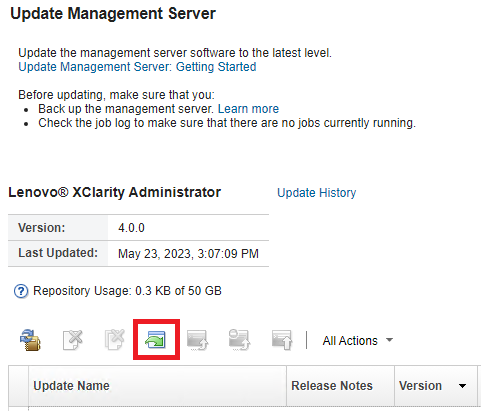
- Once at the Lenovo XClarity Administrator dashboard, click Administration, then select “Update Management Server”
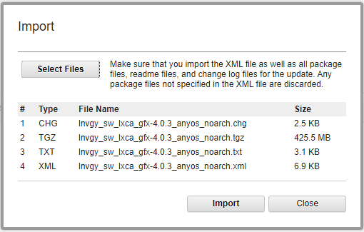
- Click the Import button to import the 4.0.3 GA fix downloaded during the prerequisites section.
- Select all files associated with the GA fix
- Once imported, select the radio button for the newly imported update and click Perform Update
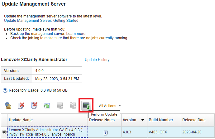
- This may be a long-running process taking several minutes.
- Log into the ESXi Host UI, navigate to the LXCA VM and launch the web console.
- Watch for the appliance to reboot back to the main login screen pictured above.
- Ignore the section to reconfigure the network either by letting it time out or by hitting X and Enter.
- Verify the new version listed is 4.0.3

- Log into LXCA and click Administration, then “Network Access”
- Click the Edit Network Access button.
- Select the required network adapter for operating system image management and deployment.
- In some cases, Eth1 may need to be configured and selected. Review the firewall requires outlined in the prerequisites section.
- If any static routes are needed, enter them in Advanced Routing.
- Click Save IP Settings, then Save.
- Click Restart at the next prompt after saving IP settings.
- This may be a long running process that takes several minutes.
- Refreshing the LXCA interface may result in “ERR_CONNECTION_REFUSED” until the services are back online.
- The appliance may not reboot if watching the web console.
- Do not manually reboot the appliance, wait for the services to come back online and provide the login prompt.
Step 6 – Deploy ESXi on remaining servers
This step will use the custom ISO created earlier in this document to create an automated OS deployment that applies the needed VCF configuration.
- Log into LXCA and click on Hardware, select “Discover and Manage New Devices” at the bottom.
- In the Discover and Manage New Devices pane, click the “Manual Input” button.
- Select the “Multiple Systems” radio button, then provide the scope of IP address for the XCC IP addresses.
- It may take several minutes to discover all new systems.
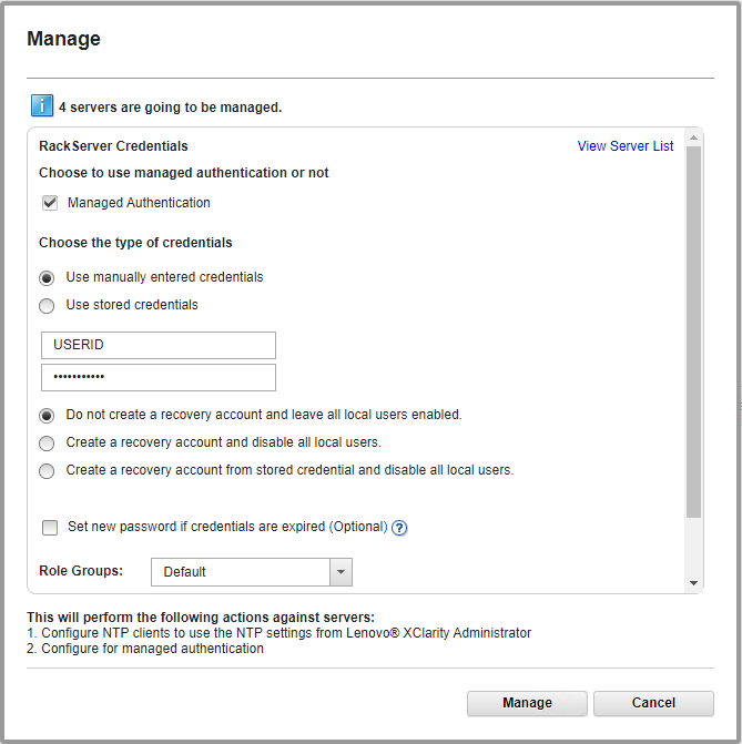
- At the Manage window, set the following configuration:
- Leave Managed Authentication Checked
- Either enter a user ID and password or create a new stored credentials
- The rest can be left as default, click Manage
- This process may take several minutes. When complete, the process bars will show Successfully managed.
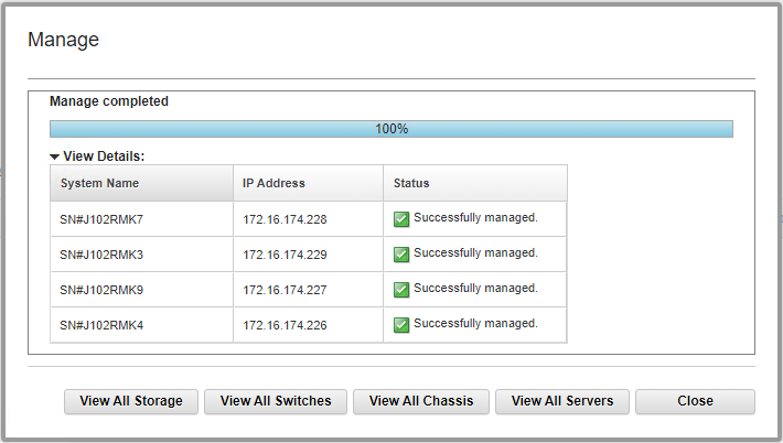
- Click View All Servers.
- The status will show “Pending” while LXCA is doing a discovery/inventory of the newly added servers. This will take several minutes.
- Click Provisioning and navigate to “Manage OS Images”.
- In the Deploy Operating Systems: Manage OS Images section, be sure OS Images tab is selected and click the import icon.
- Click Browse and locate the custom ISO created earlier in this document, then click Import.
- Verify the import was successful:
- Create the Unattend file: Click the Unattend Files tab and click the “Create Unatten File” icon.
- Change the OS Type drop down to ESXi and provide a name for the file.
- Below is an example that includes the requirements for VCF:
vmaccepteula
%include /tmp/installcfg
rootpw <change>
network --bootproto=static --ip=#predefined.hostPlatforms.networkSettings.ipAddress# --gateway=#predefined.hostPlatforms.networkSettings.gateway# --nameserver=#predefined.hostPlatforms.networkSettings.dns1#,#predefined.hostPlatforms.networkSettings.dns2# --netmask=#predefined.hostPlatforms.networkSettings.subnetMask# --hostname=#predefined.hostPlatforms.networkSettings.hostname#
reboot
#predefined.unattendSettings.preinstallConfig#
#predefined.unattendSettings.postinstallConfig#
# Locate the disk to install
%pre --interpreter=busybox
DISK=`ls /vmfs/devices/disks/ | grep M.2 | grep -v :`
echo "install --disk=$DISK --overwritevmfs" > /tmp/installcfg
%firstboot --interpreter=busybox
# VCF Prerequisites
# Enable SSH
vim-cmd hostsvc/enable_ssh
vim-cmd hostsvc/start_ssh
# NTP
esxcli system ntp set -s #predefined.otherSettings.ntpServer#
esxcli system ntp set -e 1
# Regenerate certificates to match hostname for VCF
/sbin/generate-certificates
reboot
- The example includes macros from LXCA.
- It also uses a %pre script to determine the disk to install ESXi on. This may need to be modified to fit the specific configuration of the physical servers. In this instance, the OS disk is the M.2 SATA disks.
- Edit the rootpw line to the password supplied in the Deployment Parameter Workbook.
- Click Save.
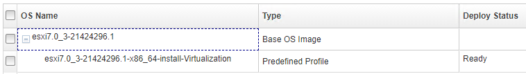
- Create the VCF profile: Click the OS Images tab and check the box next to the newly imported OS image.
- Click the Create Customized Profile icon.
- Provide a Name and Description, then select “Only unattend files” from the Customization Type drop down.
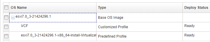
- Click the Unattend Files tab and check the box next to the unattend file create previously.
- Click Customize to create the VCF profile.
- Click Hardware and navigate to Servers to verify inventory discovery has completed.
- Click Provisioning and navigate to Deploy OS Images.
- Click the Global Settings icon and provide the ESXi root password from the Deployment Parameters Workbook
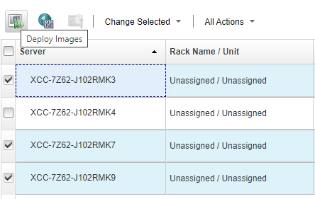
- Click the checkbox at the top left to select all servers.
- Click Change Selected and navigate to Image to Deploy.
- Select the newly created VCF profile and click OK.
- Click the checkbox at the top left to select all servers again (setting the image deselects the checkbox)
- Click Change Selected and navigate to Network Settings
- Provide the hostnames, IP addresses, Subnet Mask, Gateway, and DNS servers that match the Deployment Parameter Workbook and click OK:
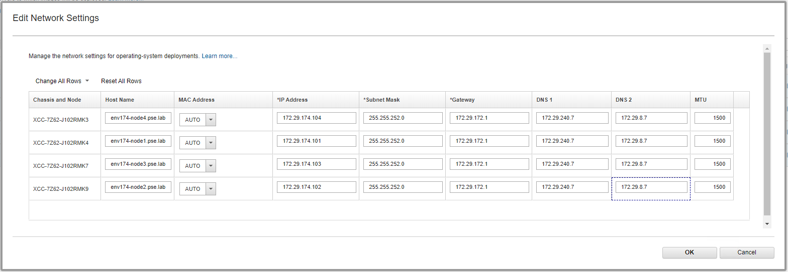
- NOTE: The storage section and global password are overridden when using a profile with an unattend file. It is possible to deploy ESXi without the unattend file example by selecting the non-VCF profile. If the non-VCF profile is selected, the storage selected will be used as the destination OS disk. VCF settings will need to be applied to any ESXi installations made without the example unattend file.
- IMPORTANT: Ensure the first server where the LXCA VM is running is now unchecked
- Click the Deploy Images icon:
- Verify the VCF unattend file is provided by the profile in the drop down. Click Deploy.
- This is a long running process.
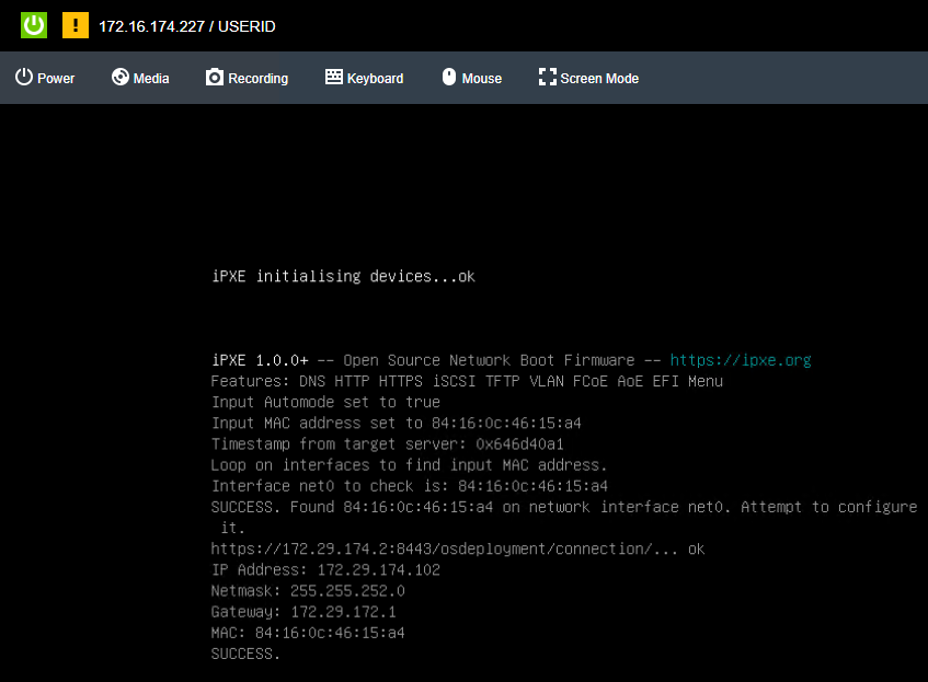
- The XCC remote console can be opened for each server to monitor the progress of the ESXi installation.
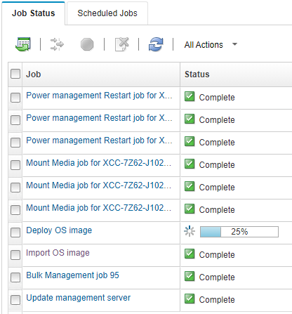
- Click the Jobs menu at the top right, then select View All Jobs at the bottom to monitor the OS deployment tasks:
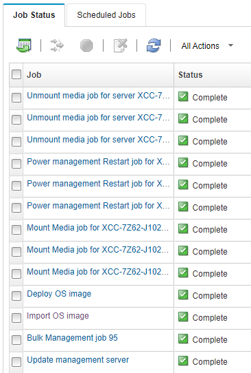
- LXCA will unmount the virtual media when OS deployment is completed:
Step 7 – Deploy VMware Private Cloud
VMware Cloud Foundation is deployed using VMware Cloud Builder. Cloud Builder performs validation on the parameters supplied in the Deployment Parameter Workbook to ensure configuration is correct and meets the prerequisites. This is a long running step and will take several hours to complete.
- Log into the Host UI of the first ESXi host and verify there’s adequate local storage to deploy the VMware Cloud Builder appliance.
- With Host selected on the left Navigator pane, click Create/Register VM.
- Select Deploy a virtual machine from an OVF or OVA file and click Next.
- Provide a name and locate the Cloud Builder OVA downloaded previously and click Next
- Select the local datastore, agree to the license agreement.
- Select the network port group that allows the Cloud Builder VM to communicate with all nodes & networks. It is preferred to use the management network.
- Set disk provisioning to Thin, select the checkbox to power on automatically, click Next.
- Provide all the parameters under Additional settings. DNS and NTP server(s) should match what was supplied in the Deployment Parameter Workbook.
- Verify all settings and supplied properties, then click Finish.
- Once the Cloud Builder appliance is deployed & powered on, verify it is online by accessing the web interface by navigating to either it’s IP address or FQDN. A VMware Cloud Builder login prompt will be displayed if successful:
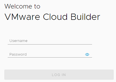
- Login with the credentials supplied during the OVA deployment, check the box to agree to the license agreement and click Next.
- Select the radio button for VMware Cloud Foundation and click Next.
- Read through the Prerequisites section to ensure all are met. Check the box signifying all prerequisites are configured and click Next.
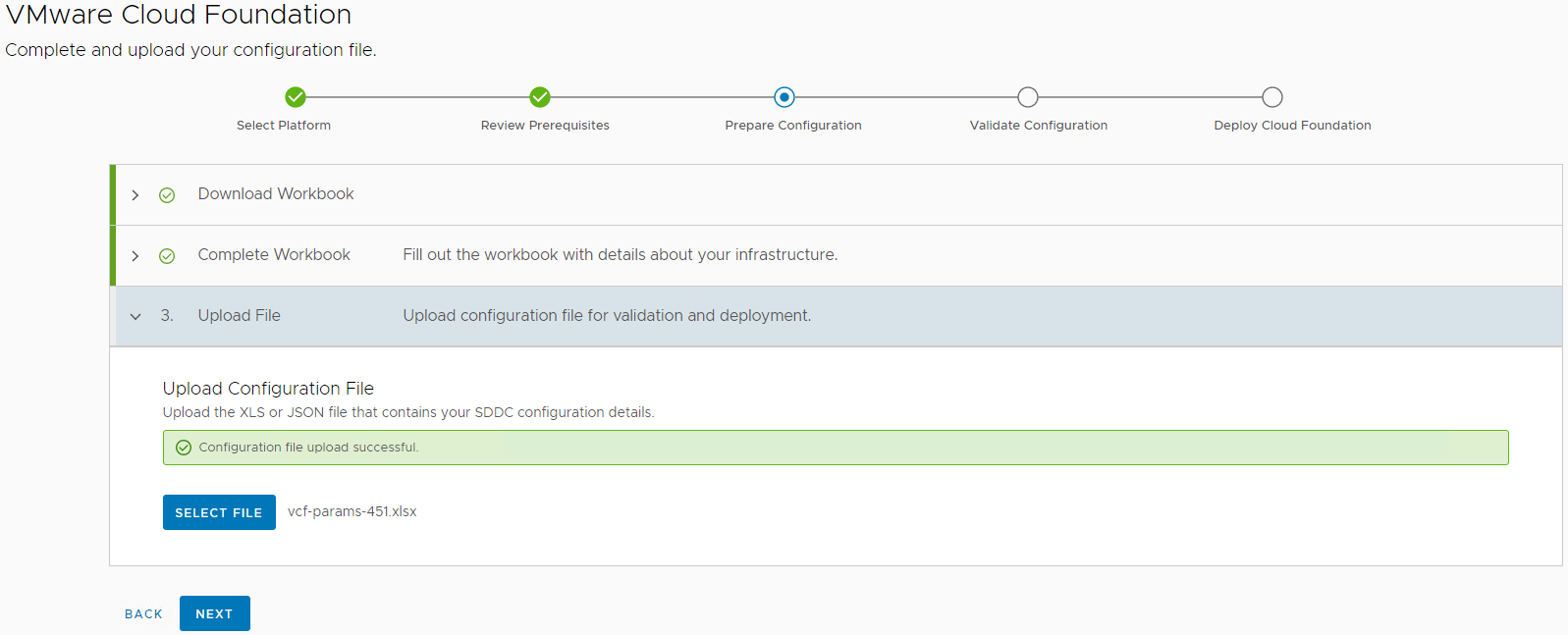
- If the Deployment Parameter Workbook is not already completed, download the file, click next, and revert to the Complete Deployment Parameter Workbook section of this document. Once the document is completed, click Next.
- Supply the completed Deployment Parameter Workbook and click Next.
- The next step validates all parameters supplied in the Deployment Parameter Workbook, as well as all validates all prerequisites are in place prior to deploying Cloud Foundation.
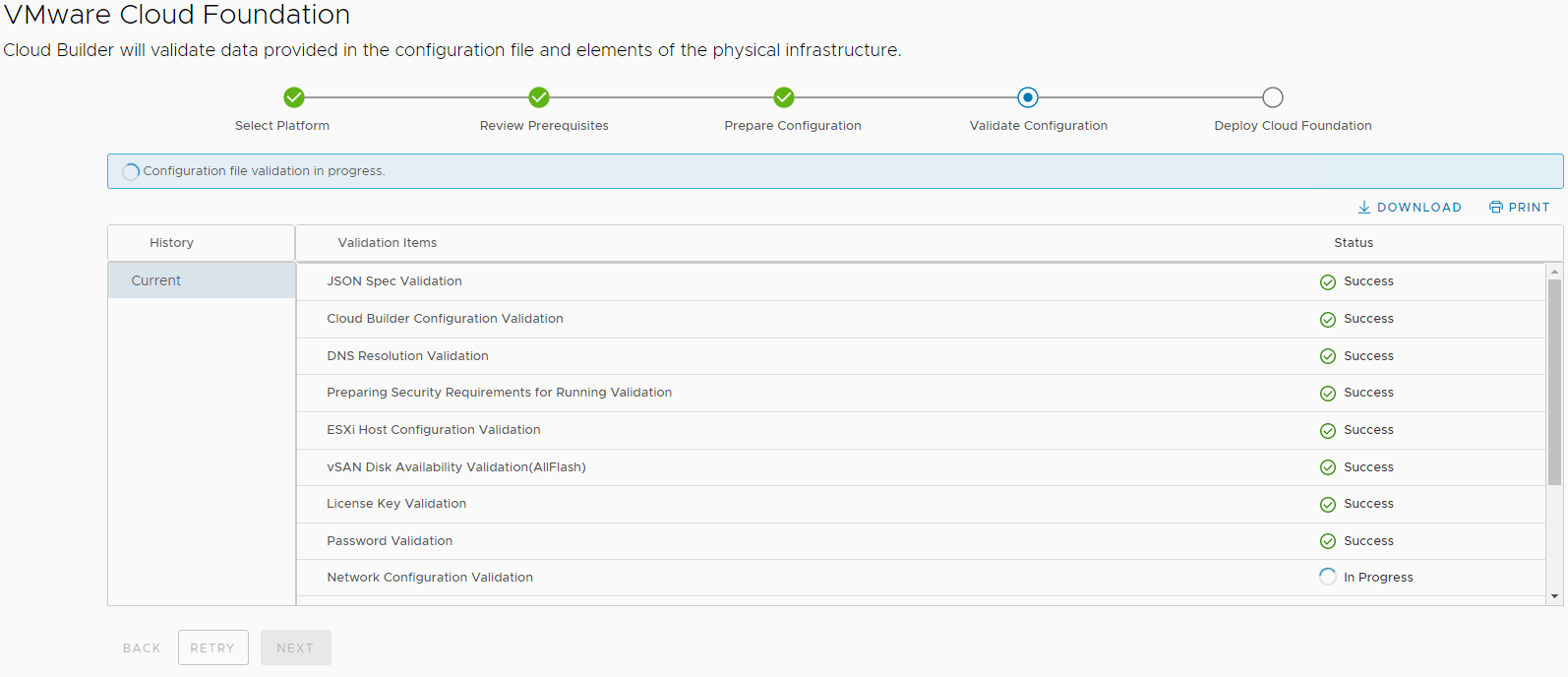
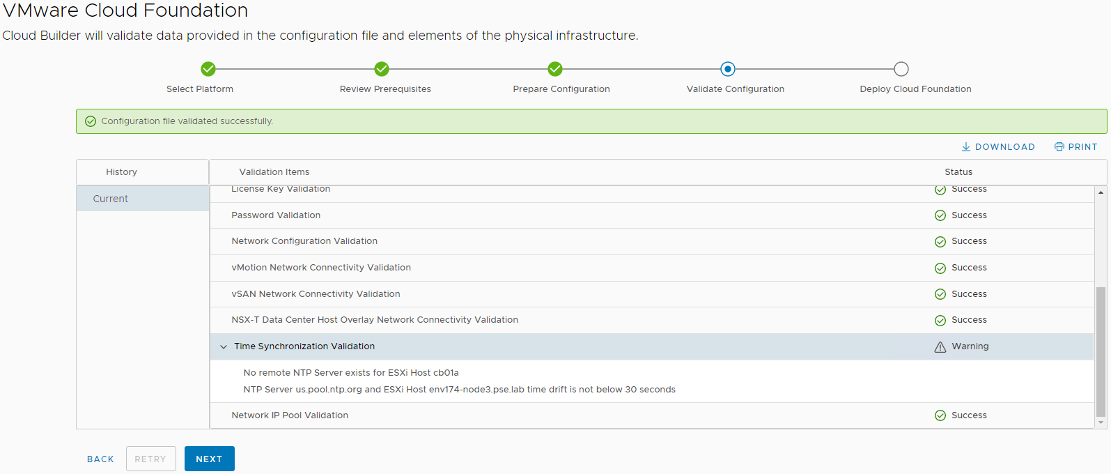
- Correct any errors and click Retry until everything validates successfully. Once validated successfully, click Next.
- Some NTP warnings can be ignored if all ESXi hosts are configured with the same NTP server, the service is running, and time is in-sync:
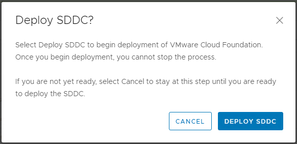
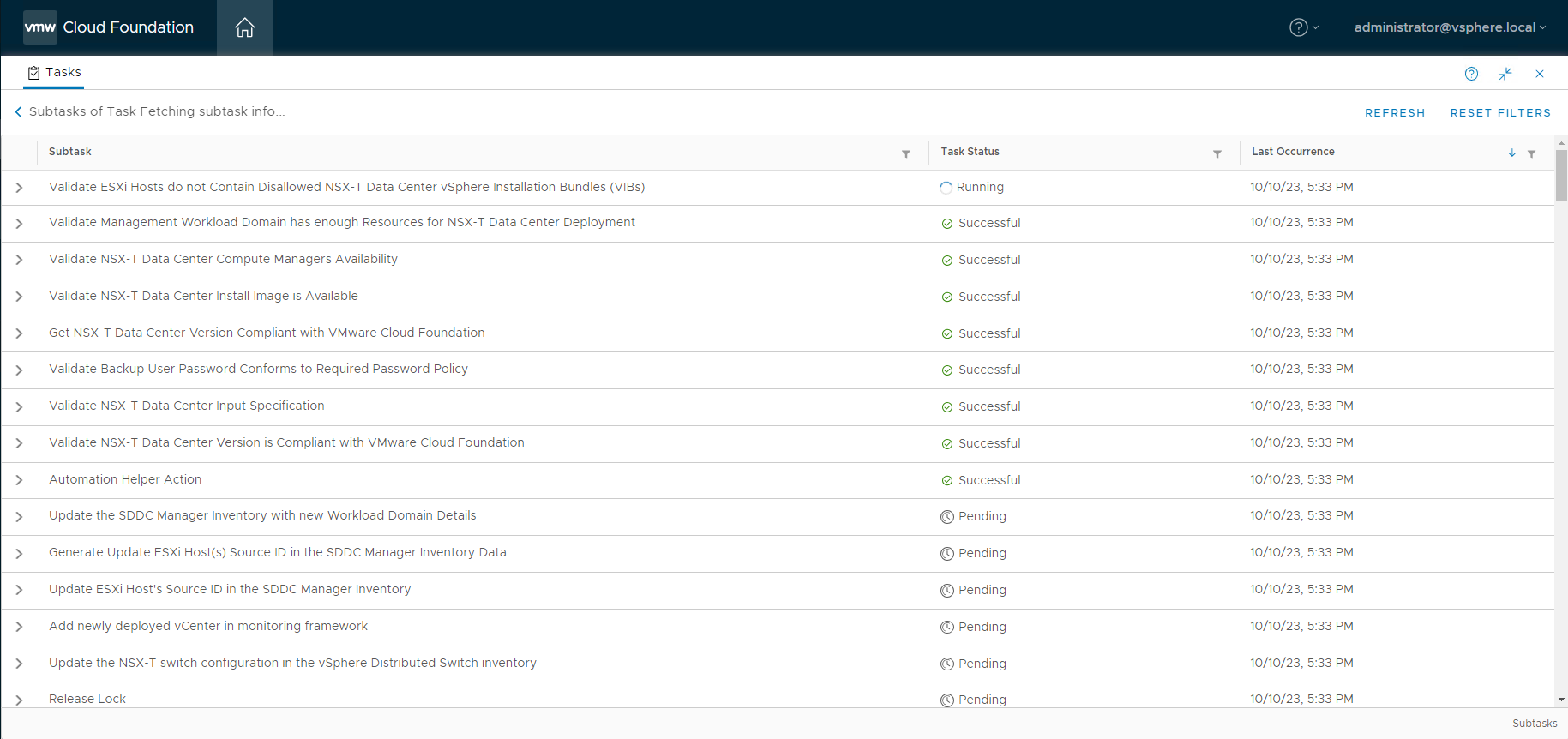
- If you are ready to deploy the SDDC, this step is also called Bring Up, click Deploy SDDC in the dialog box to begin the Bring Up process:
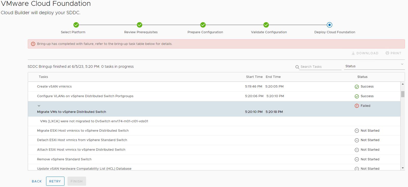
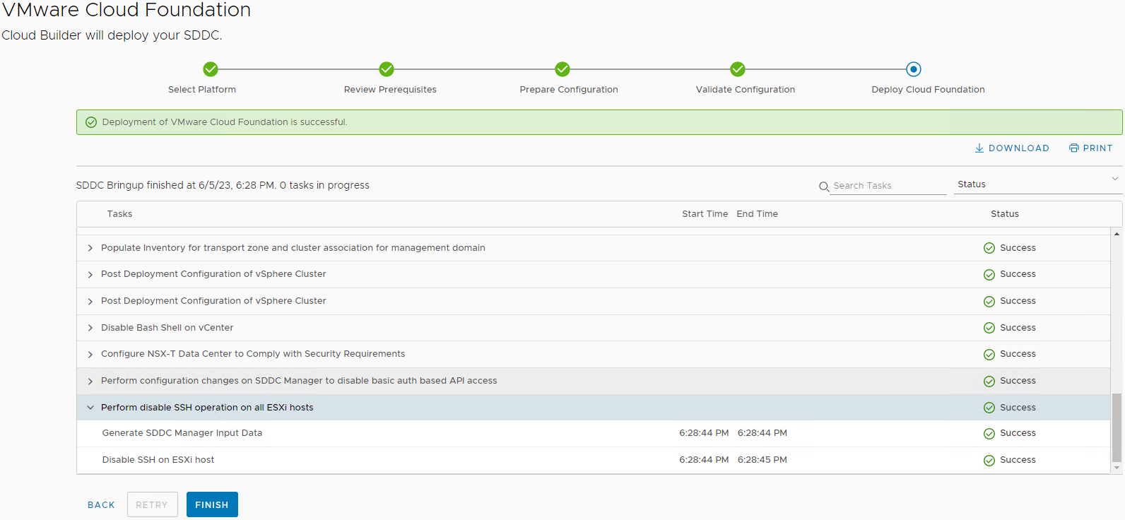
- Bring Up is a long running process and may take several hours to complete. If there are any errors, correct the configuration issue and click Retry.
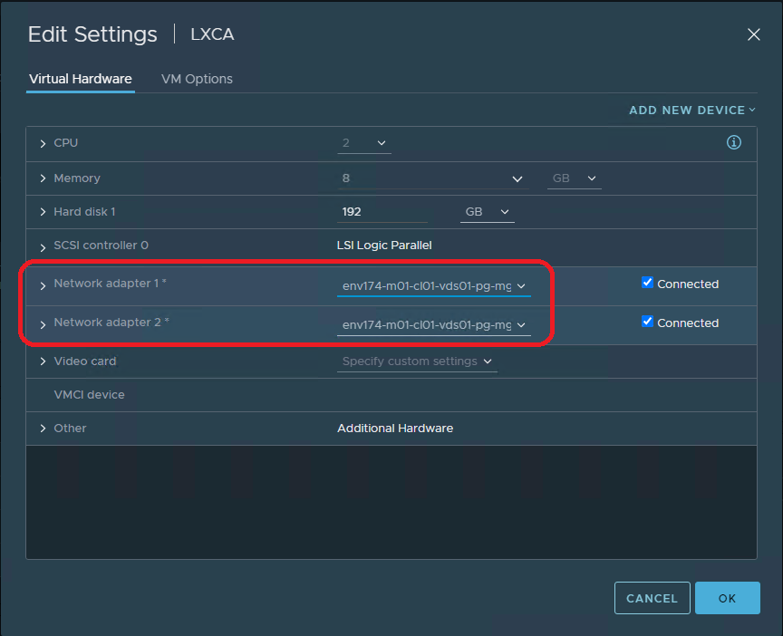
- This document assumes LXCA is running in the environment being deployed, Cloud Builder won’t migrate the networking and will stop. Log into the newly deployed vCenter and manually move the network adapter to the newly created distributed port group and click Retry
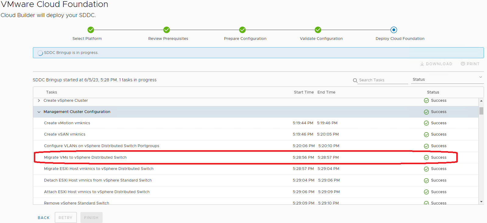
- When Bring Up is completed, click the Finish button:
- Cloud Builder has successfully deployed the new VMware Cloud Foundation SDDC. Click Launch SDDC Manager to view the newly deployed environment:
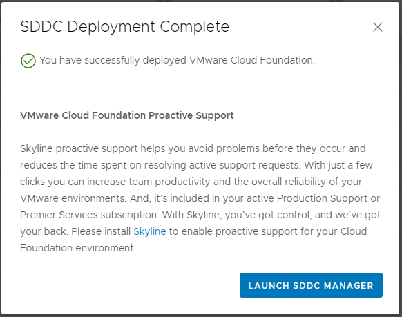
- At this point, the Cloud Builder appliance can be powered off and deleted from disk.
Step 8 – Deploy Lenovo XClarity Integrator for VMware vCenter
- Log into the vCenter UI, click the Navigation menu on the left and select Inventory.
- Right-click on the desired cluster and select Deploy OVF Template.
- Provide the LXCI file downloaded at the beginning of this document, lnvgy_sw_vmuim_102-8.2.0_vmware_x86-64.ova
- Provide the Virtual Machine name, select the folder, and click Next.
- Select the compute resource, either cluster or resource pool, click Next.
- Under Review details, click Next.
- Select the desired storage location and click Next.
- Select the desired port group, leave IP allocation and IP protocol as Static – Manual and IPv4, respectively.
- Under Customize template, provide the following information:
- Leave IP allocation and IP protocol as default.
- Provide IP address, Netmask, and Gateway.
- Provide the Host name & Domain name.
- Provide the DNS servers supplied in the Deployment Parameter Workbook, click Next.
- Click Finish and wait for the OVA template to deploy, then power it on.
- This screen indicates when the initially deployment is completed:
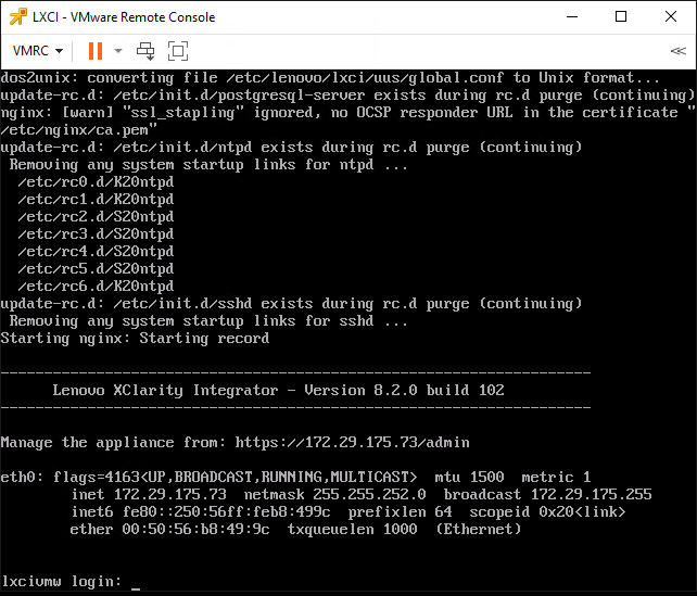
- Navigate to the LXCI web interface displayed on the console:
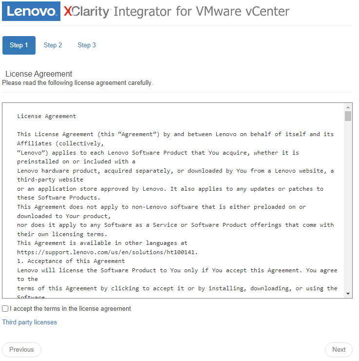
- Check the box to accept the license agreement and click Next.
- Verify the network settings are correct and click Next:

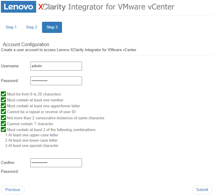
- Provide a username & password for the LXCI appliance and click Submit:
- Once completed, the wizard will redirect to the LXCI login interface. Provide the credentials supplied and click Login.
- Navigate to the Date And Time section on the left pane.
- Set Region & Time Zone
- Select the radio button for Synchronize with NTP server and provide the NTP server utilized in the Deployment Parameter Workbook
- Clicking Save will prompt to reboot the LXCI appliance for the changes to take effect.
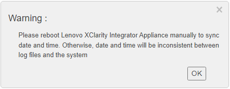
- Click OK, then click Power Control on the top right:
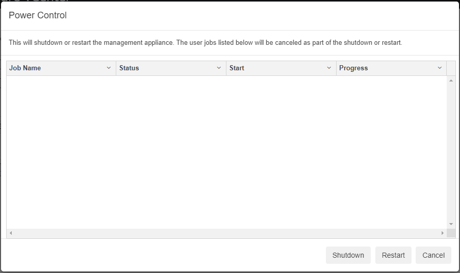
- Click Restart and wait for the appliance to reboot.
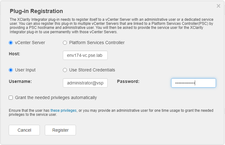
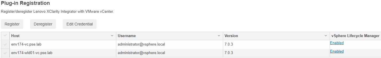
- After reboot, navigate to vCenter Connection and click Register:
- Provide the vCenter FQDN, Username, and Password, then click Register:
- Repeat if you have additional Workload Domains.
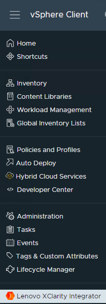
- Once registration is complete, navigate to the vSphere Client, click the Navigation menu and select Lenovo XClarity Integrator at the bottom:
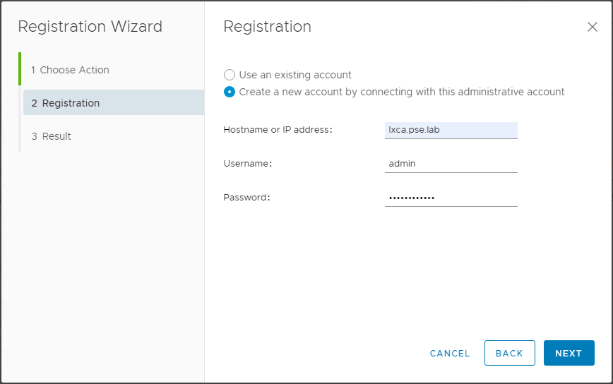
- Click ADD LENOVO XCLARITY ADMINISTATOR, provide a Hostname, Username, and Password:
- This integrates LXCI and LXCA together into vCenter:
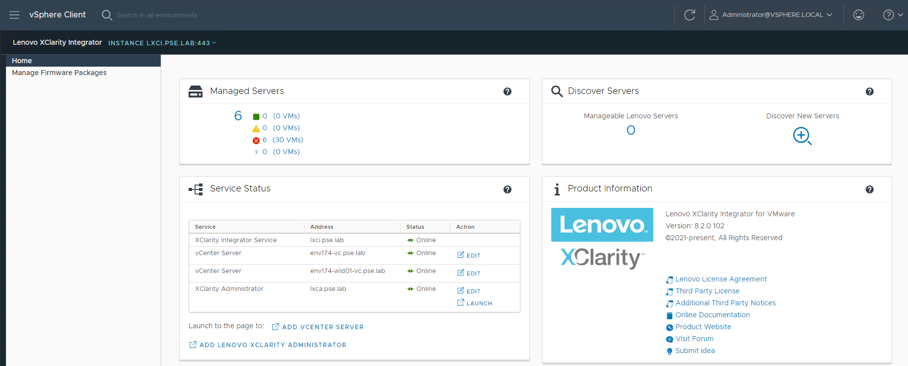
- It’s possible to download firmware packages to deploy directly in vCenter through vSphere Lifecycle Management:
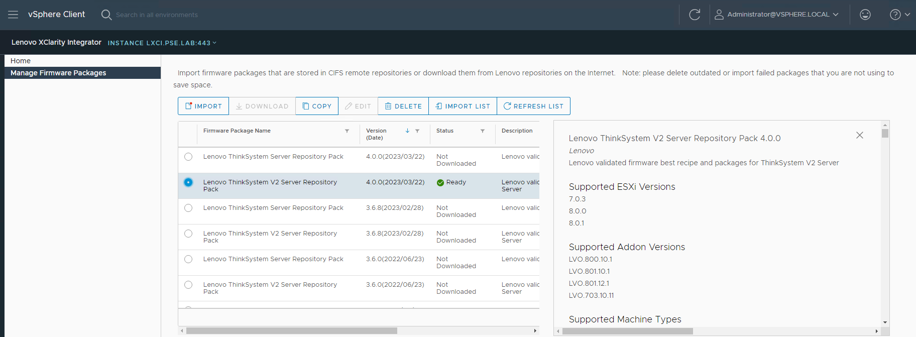
- It’s also possible to bring in Firmware Policies from LXCA and patch at the cluster level:
Step 9 – Deploy VI Workload Domain – OPTIONAL
Caution must be taken when deploying new VI Workload Domains or clusters. If it is intended to use the new vSphere Lifecycle Management (vLCM) feature introduced in vSphere 7, the image must be applied during the cluster creation process. For more information on vLCM, see the following: https://core.vmware.com/resource/introducing-vsphere-lifecycle-management-vlcm
*NOTE* - DO NOT apply a vLCM image to any pre-existing clusters inside vCenter, as this may result in the inability to apply ESXi upgrades in the future. Please see the following: https://kb.vmware.com/s/article/93220
Workload domains consist of their own vCenter and NSX managers that are separate from the management domain. The workload domain vCenter will join the SSO domain of the management domain, but NSX will remain separate. Ensure the following configuration items:
- DNS
- vCenter
- NSX Managers
- A, B, and C
- Cluster VIP
- Any planned NSX Edge nodes
- These are not deployed during workload domain creation
- Networking
- NSX Overlay VLANs for hosts and edges
- Edge overlay network is needed if/when edge nodes are deployed
- NSX Overlay VLANs for hosts and edges
The following steps walk through creating a VI Workload Domain with a vLCM image. At a high level, an empty cluster must be created and the image settings applied, then imported into SDDC Manager. Let’s get started.
- Create cluster image
- Log into vCenter, ensure to be in the Hosts and Clusters view
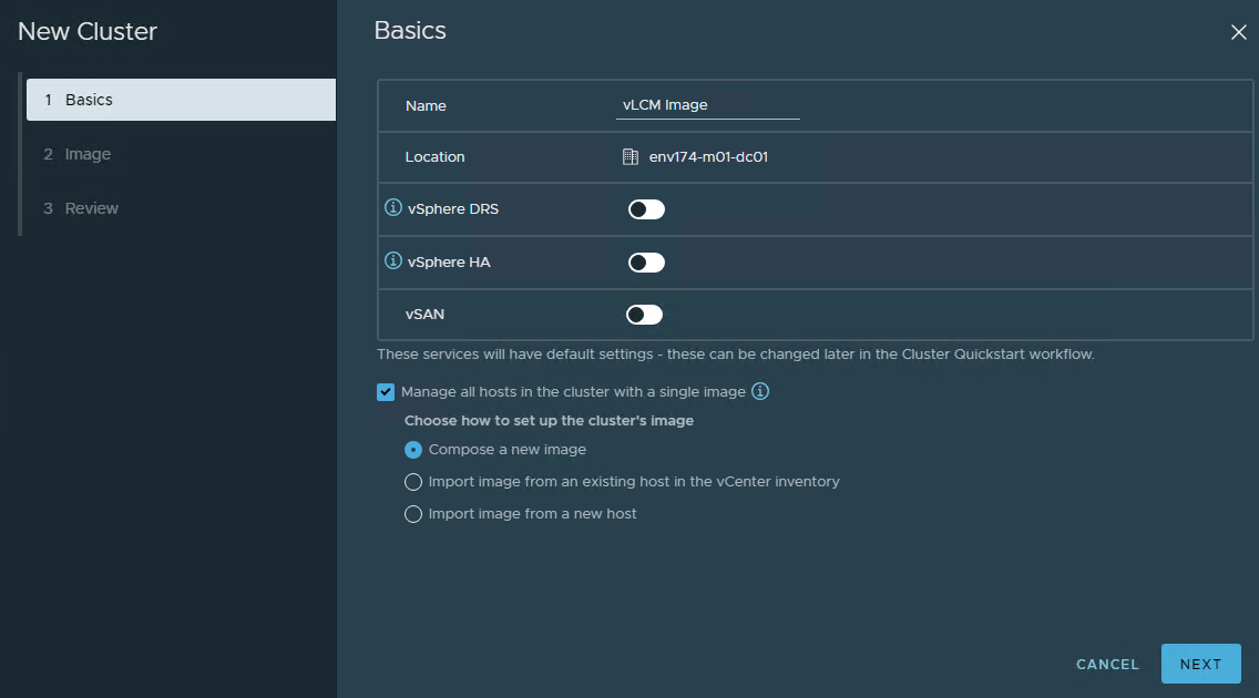
- Right-click on the virtual datacenter and select New Cluster
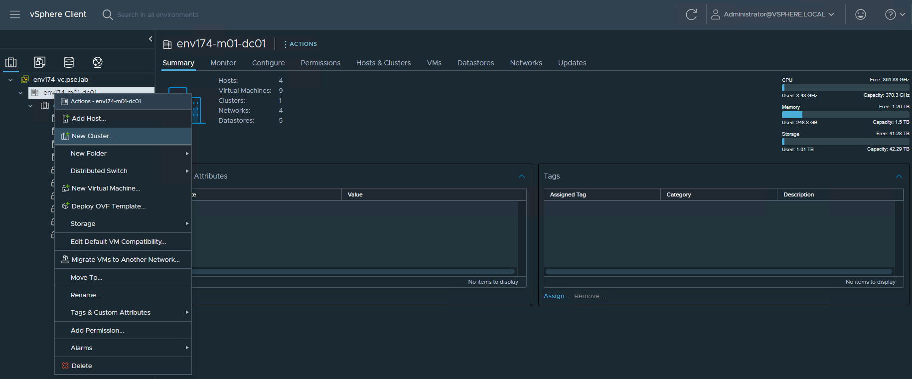
- Provide a descriptive name, leave DRS, HA, and vSAN disabled, check the box for Manage all hosts in the cluster with a single image and select Compose a new image
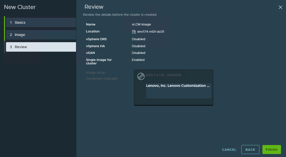
- Select 7.0 U3l – 21424296 for the ESXi Version, and the appropriate Lenovo Customization Addon for the servers being deployed
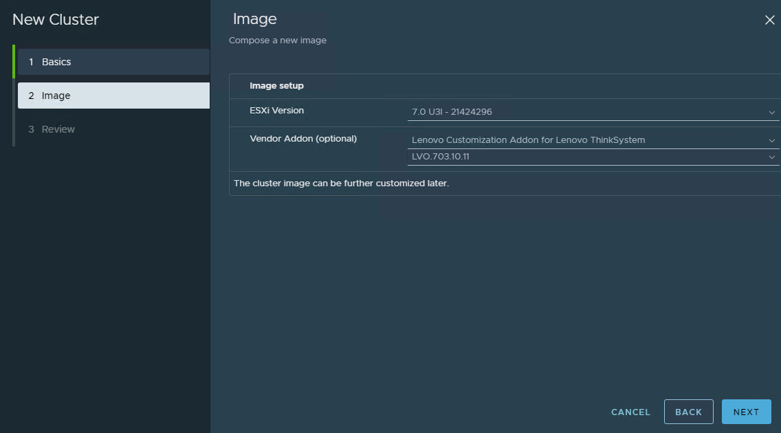
- Then click FINISH to create the empty cluster with the vLCM Image
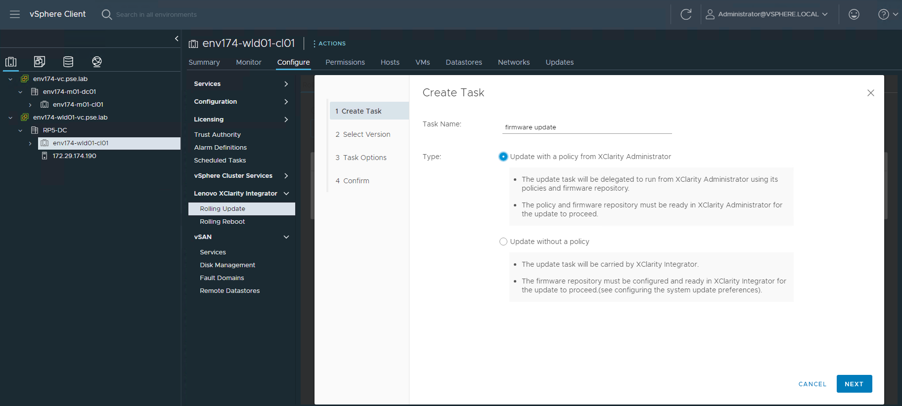
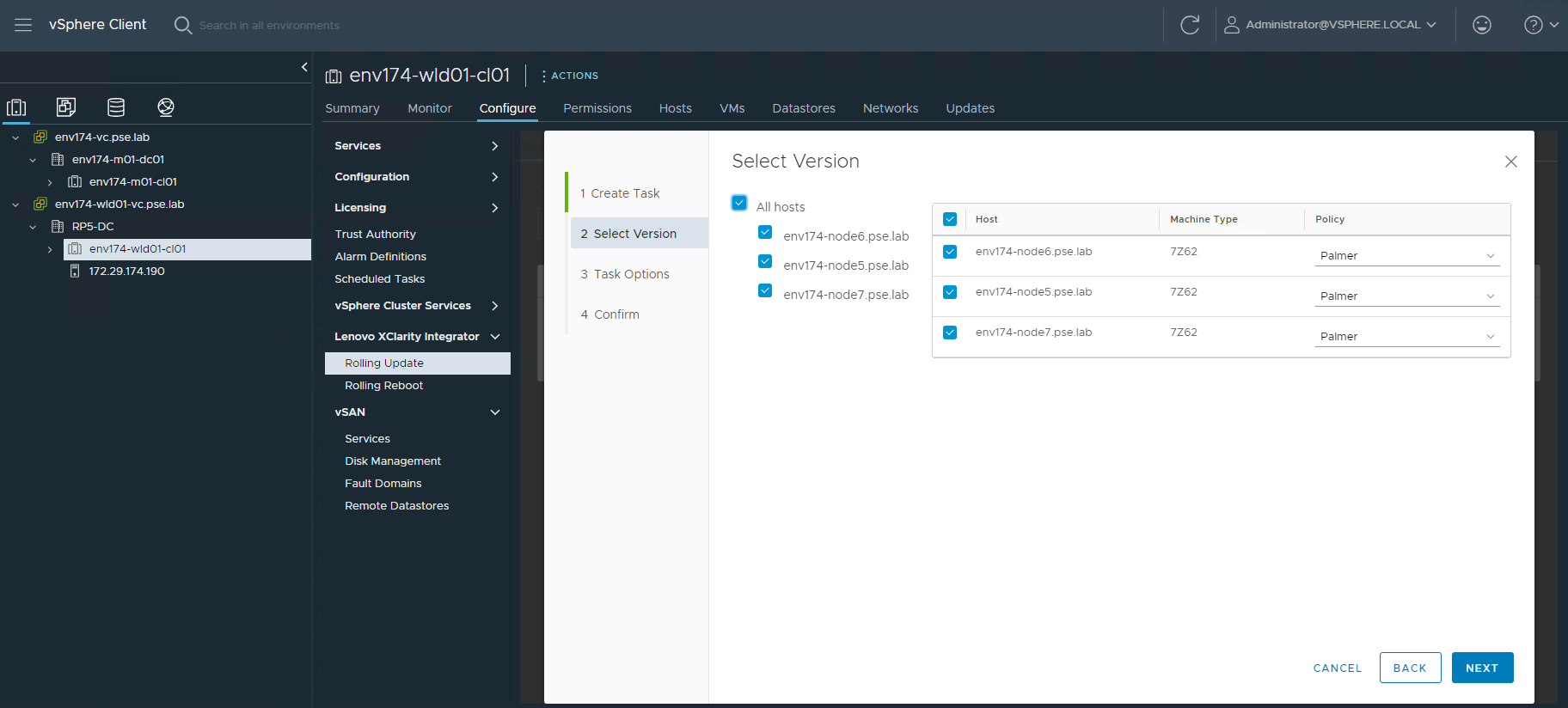
- Now that the cluster is created and vLCM image applied, we must update it to include firmware updates. Click EDIT on the top right
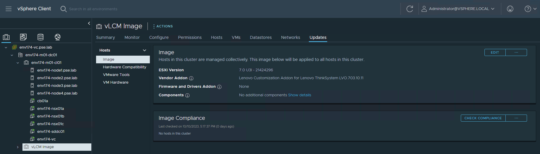
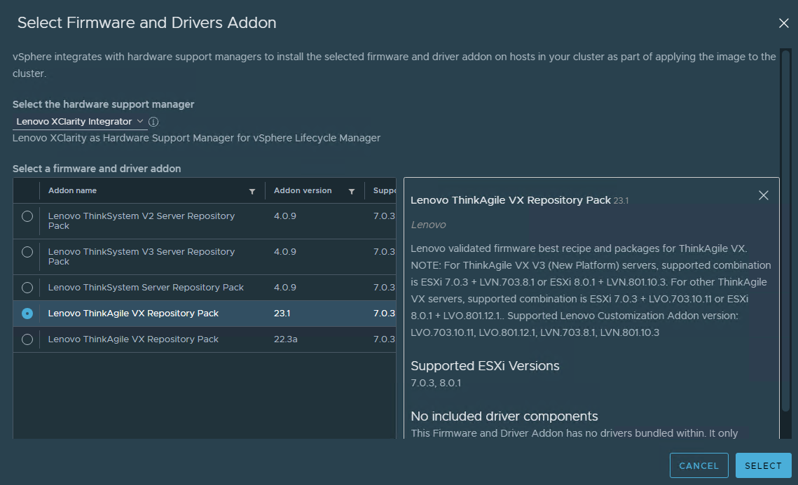
- Next to Firmware and Drivers Addon, click SELECT
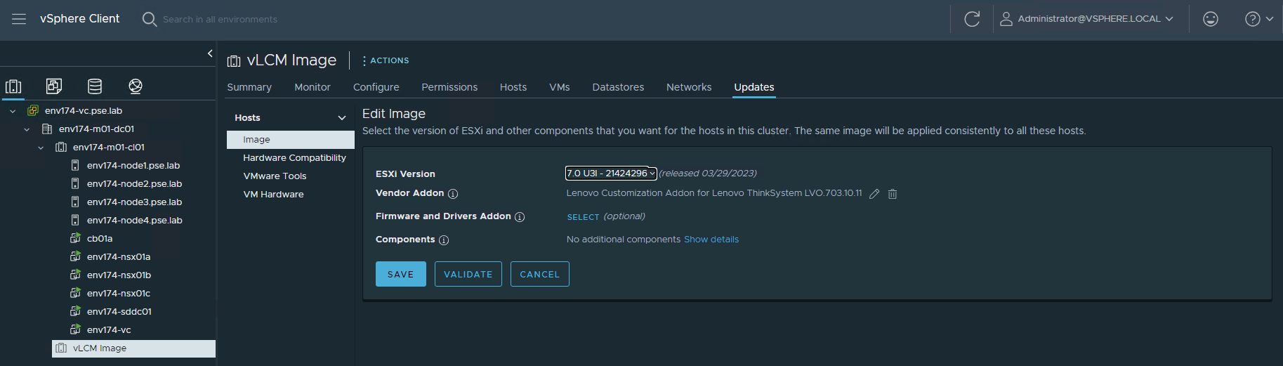
- Select Lenovo XClarity Integrator as the hardware support manager (HSM), then select the latest Repository Pack that is supported
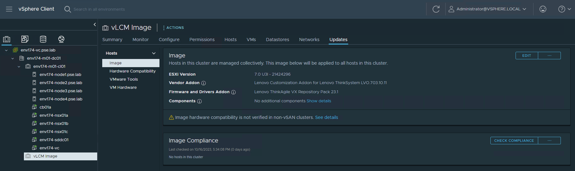
- Verify the Image settings and click SAVE

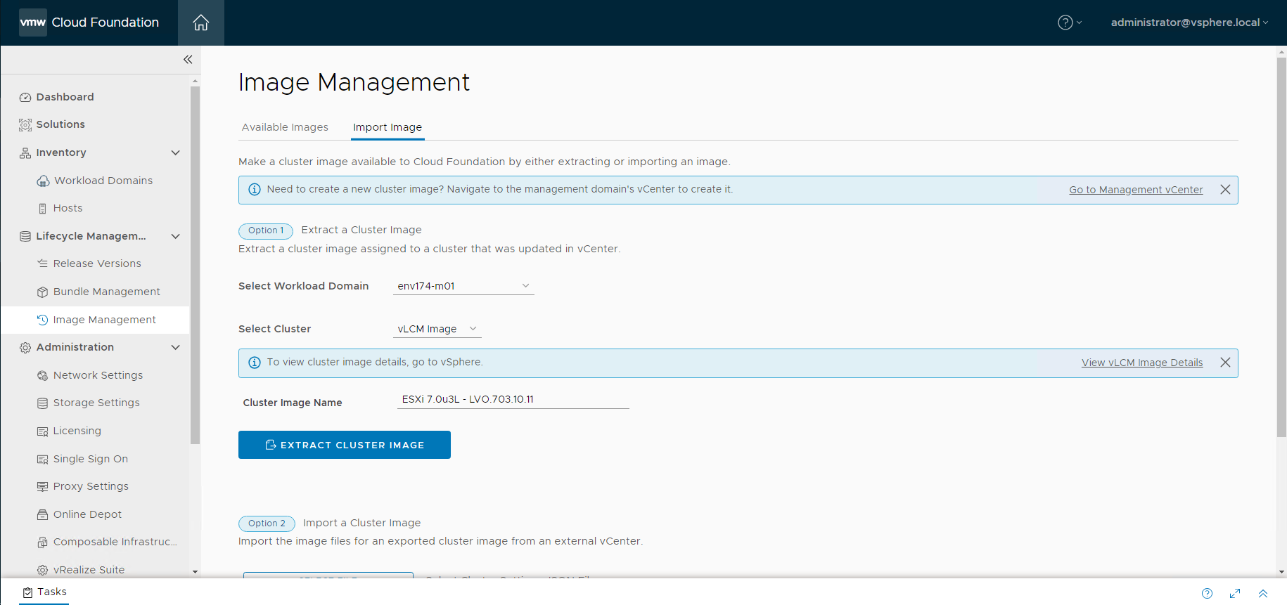
- Import vLCM into SDDC Manager
- Log into SDDC Manager and navigate to Image Management under Lifecycle Management
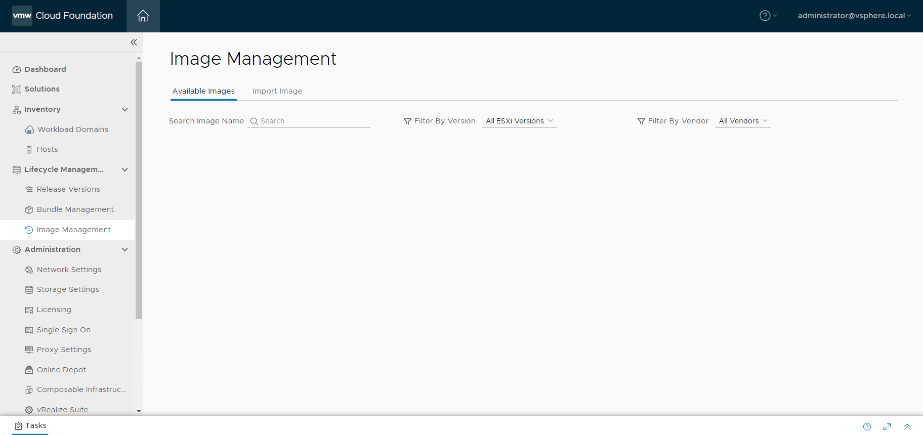
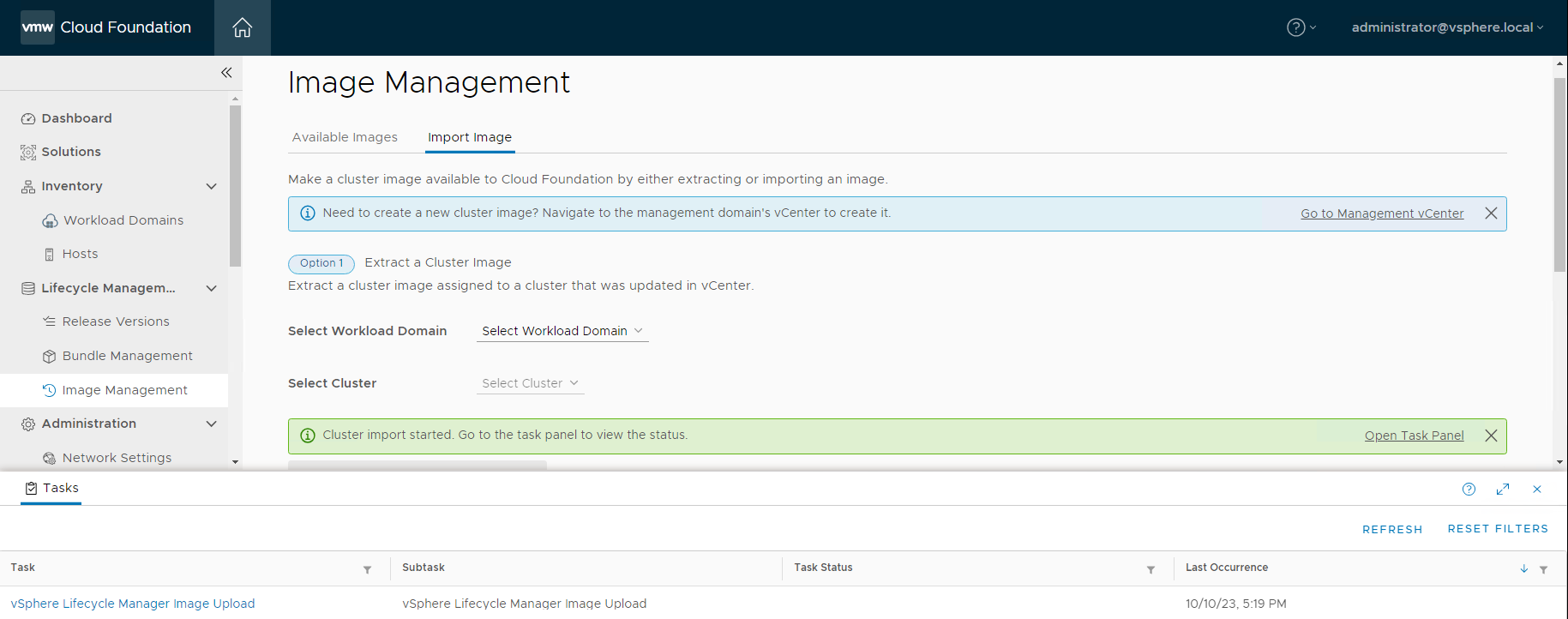
- Navigate to the Import Image tab, select the workload domain where the empty cluster was created, then select the cluster. Provide a descriptive name of the image being imported, then click EXTRACT CLUSTER IMAGE
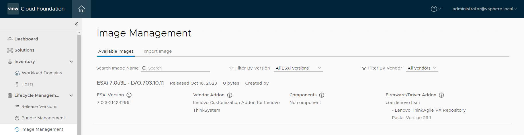
- Navigate to Available Images to view the newly imported image and the configurations associated with it
- Commission new ESXi hosts in SDDC Manager
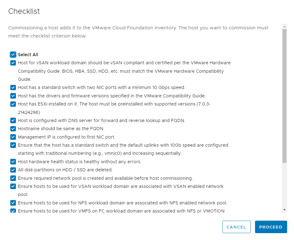
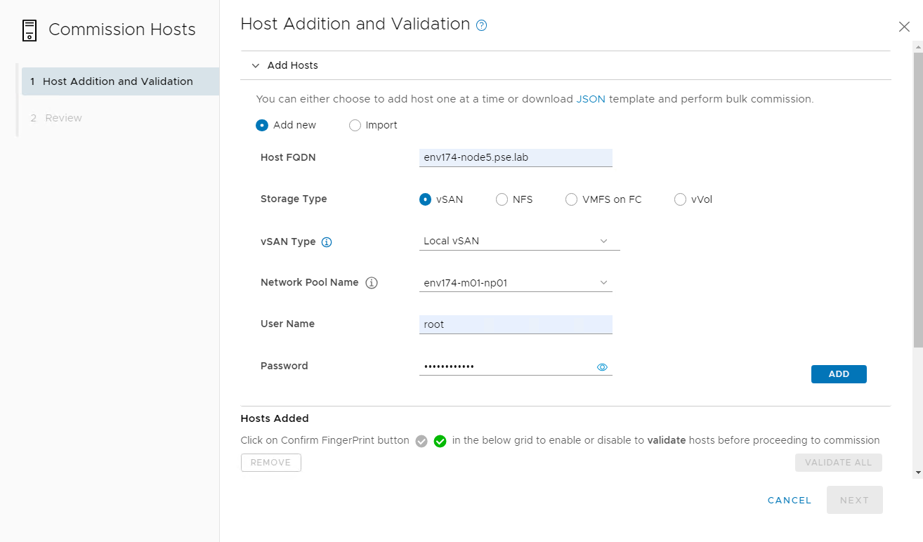
- Log into SDDC Manager, navigate to Hosts under Inventory, then click COMMISSION HOSTS
- Ensure the hosts meet all requirements
- Add the host FQDN, select the storage type, provide the network pool, login credentials, and click ADD
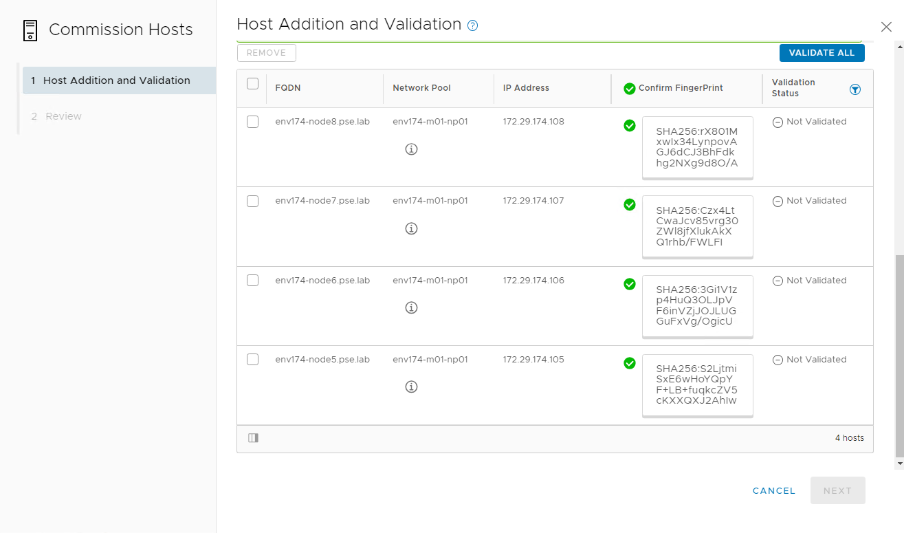
- After all nodes are added, click the checkbox to confirm the fingerprints of the nodes, then click VALIDATE ALL
- Create VI Workload Domain
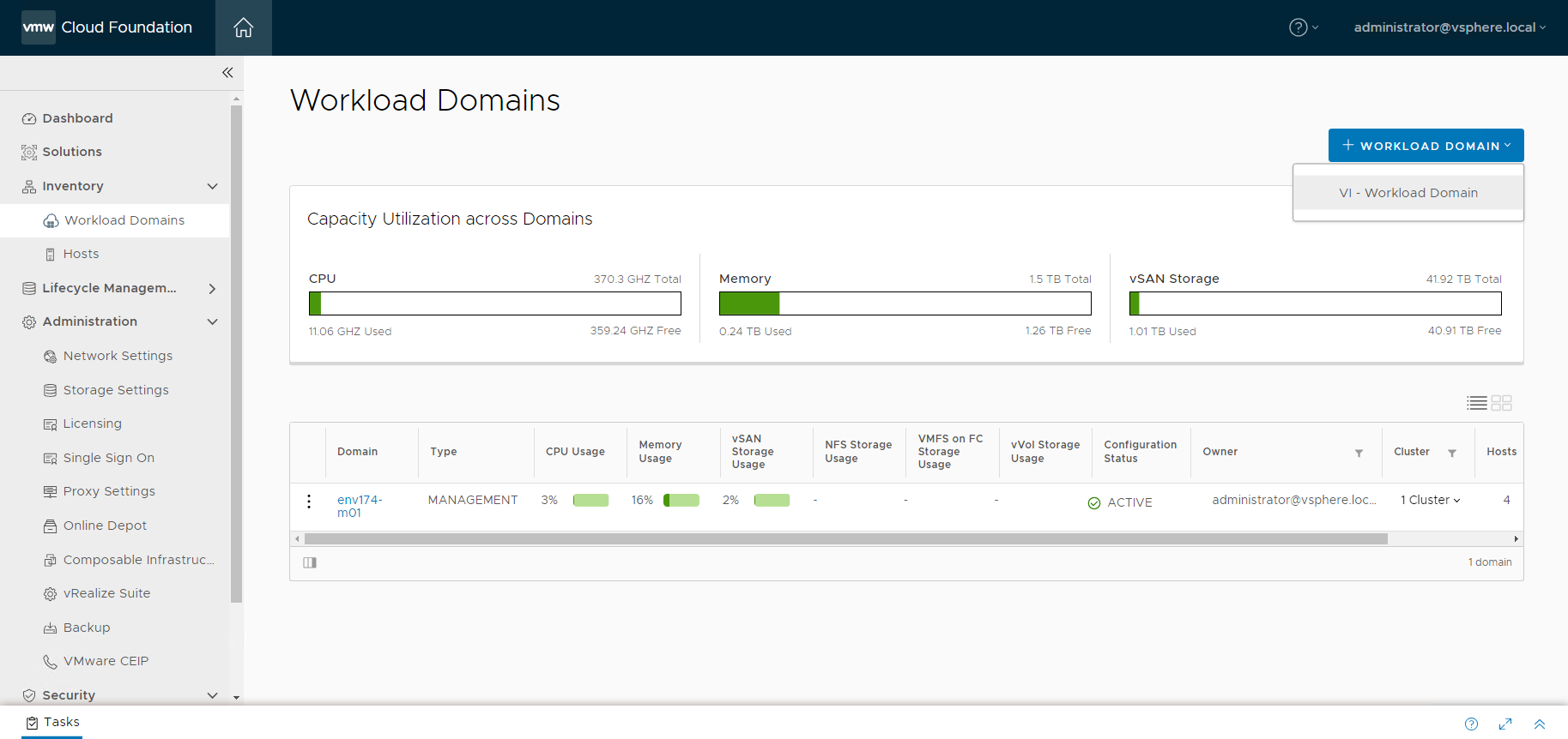
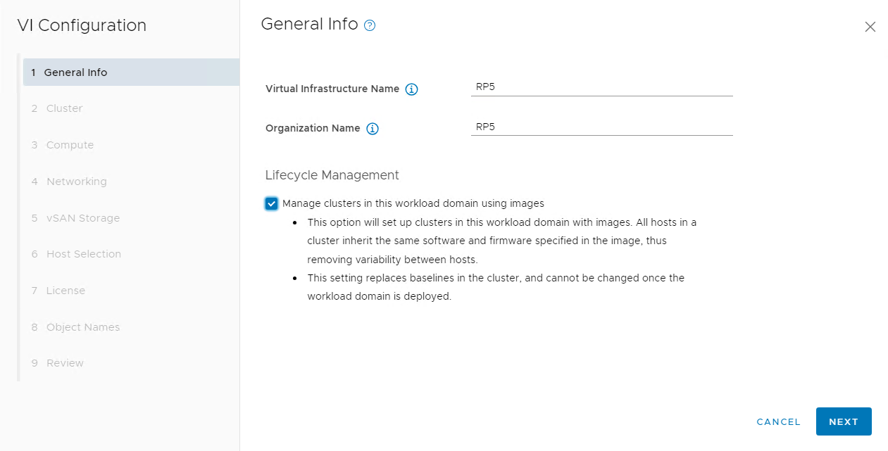
- Navigate to Workload Domains under Inventory, click + WORKLOAD DOMAIN and select VI – Workload Domain
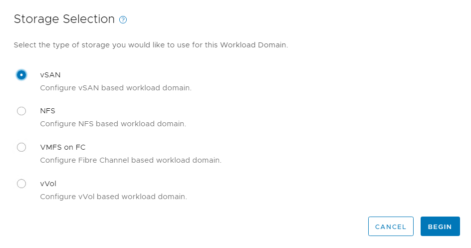
- Select vSAN and click BEGIN
- Provide a name for the new Workload Domain and check the box for Manage clusters in this workload domain using images
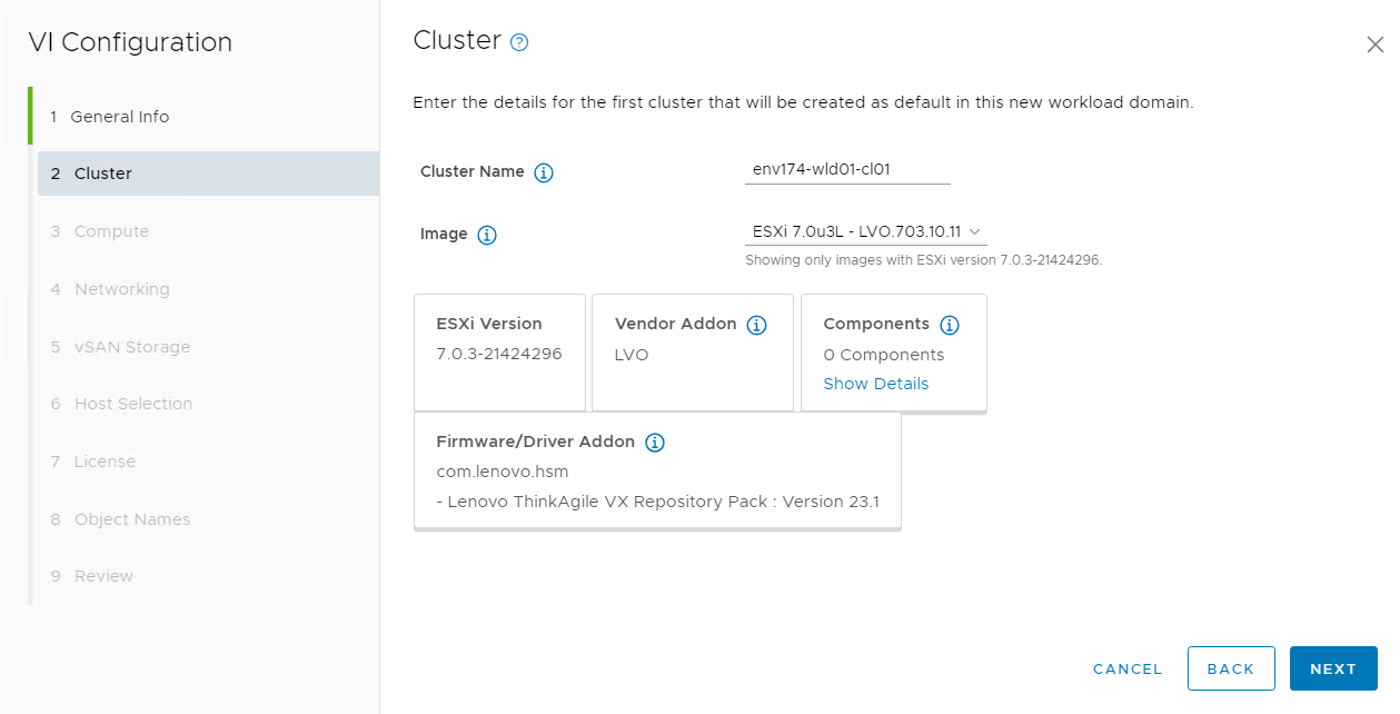
- Provide a name for the cluster and select the image that was previously imported
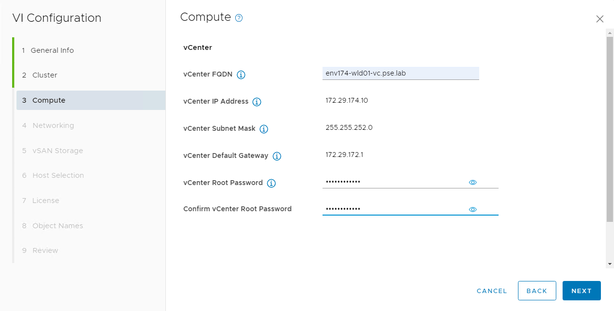
- Provide the FQDN for the workload domain vCenter, as well as the appliance credentials
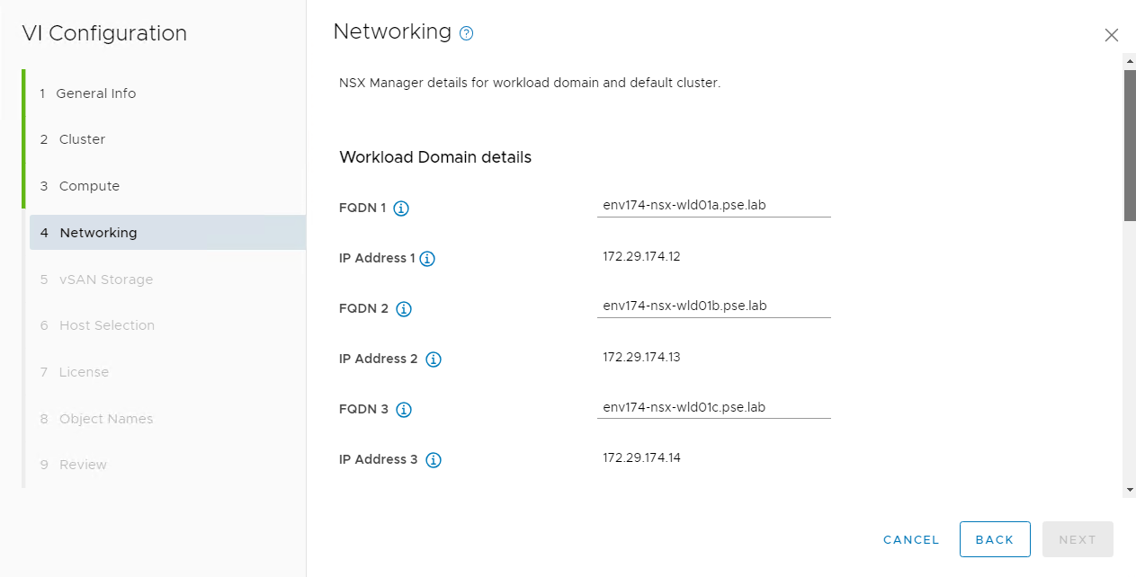
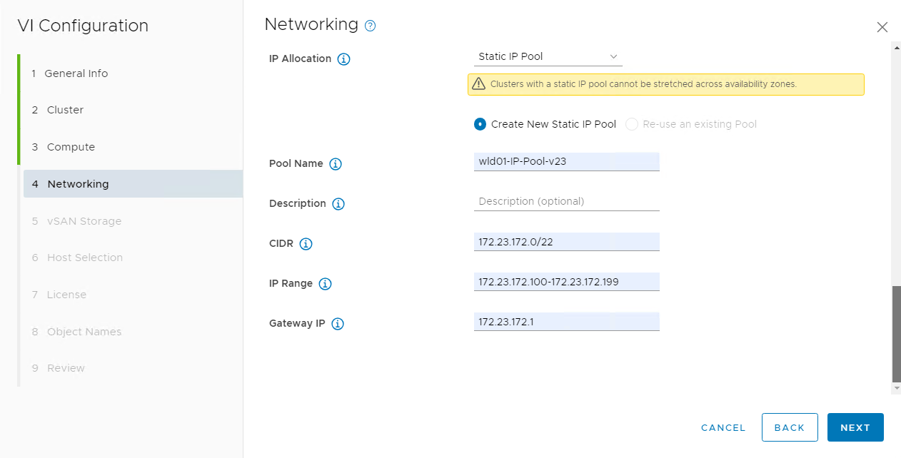
- The network section requires multiple components:
- Three NSX manager FQDNs and one cluster VIP FQDN
- NSX Manager and appliance credentials
- IP configuration for host overlay
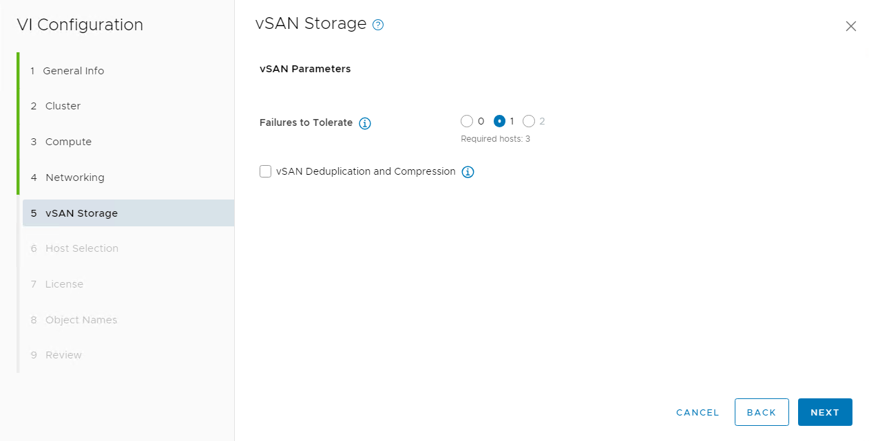
- Select the desired vSAN configuration
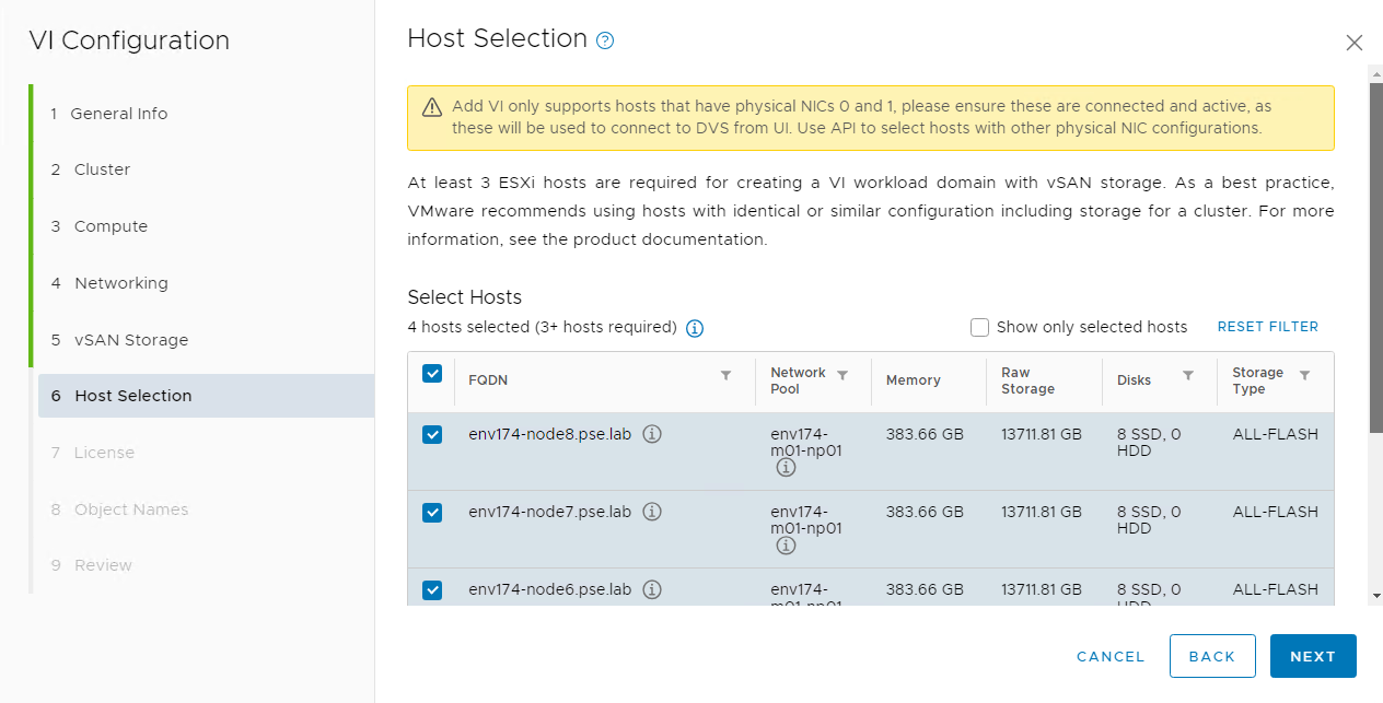
- Select the desired hosts to build out the workload domain’s cluster
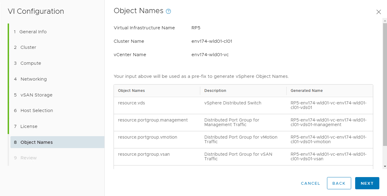
- Verify the object names for everything being created in the workload domain and then begin deployment
- This is a long running task that may take several hours to complete
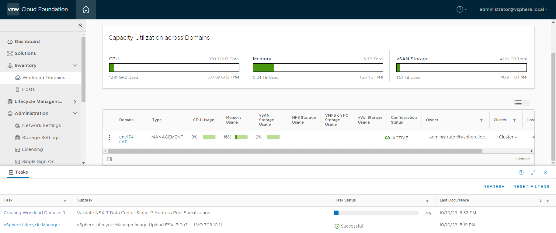
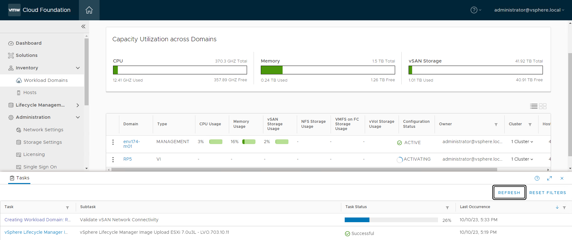
*IMPORTANT* - Workload domain creation may fail at the step of applying the cluster image. This is due to the HSM not being registered to the newly deployed vCenter, in this case Lenovo XClarity Integrator (LXCI). Once the vCenter is deployed and online, log in to LXCI and register the newly created vCenter. If the workload domain creation task failed, click RETRY once LXCI is registered to the new vCenter.
- Once completed, the newly created workload domain will register as ACTIVE
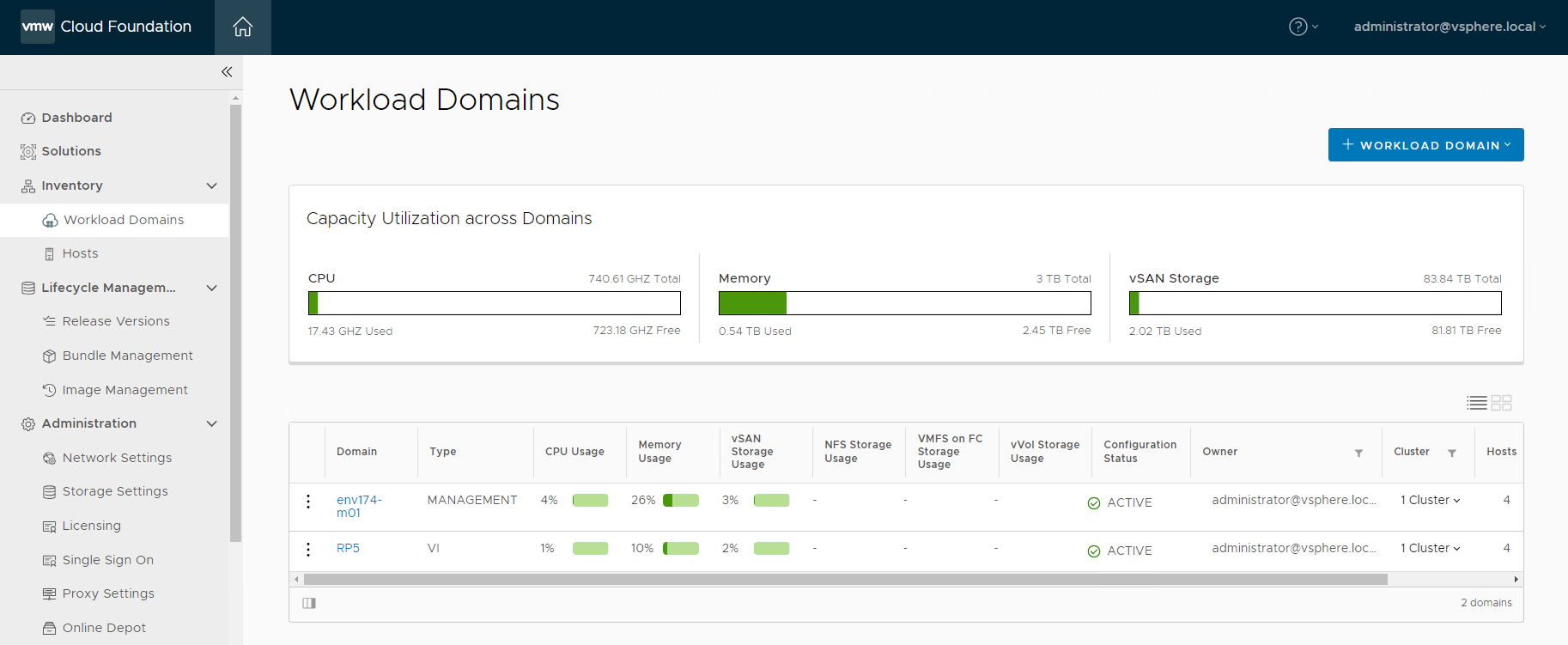
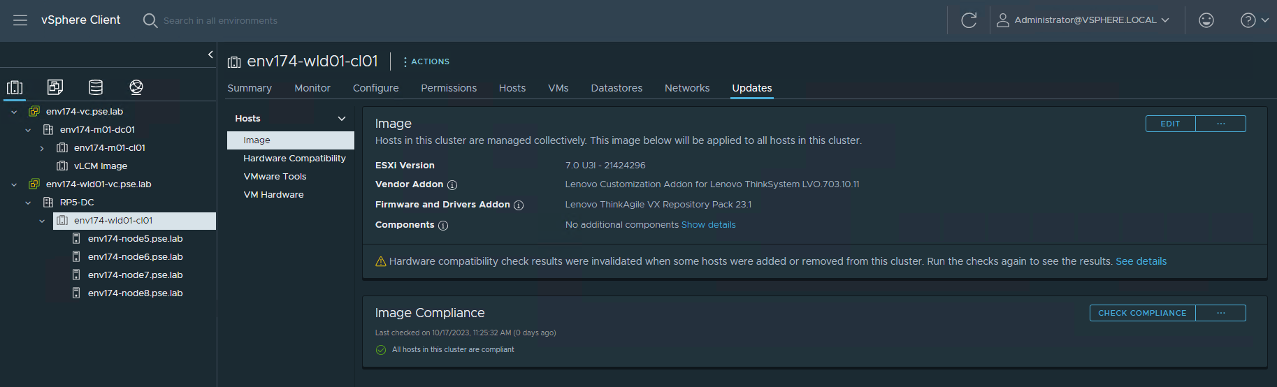
- Log into vCenter, navigate to the newly created cluster and select the Updates tab to verify the image was applied and all nodes are compliant
- Delete the vLCM Image cluster
Step 10 – Deploy Azure VMware Solution
For instructions regarding the deployment of Azure VMware Solution (AVS), please see the following documentation: https://learn.microsoft.com/en-us/azure/azure-vmware/deploy-azure-vmware-solution?tabs=azure-portal
AVS requires a single /22 network to deploy the management components of the hosted SDDC stack. All infrastructure items will be assigned IP addresses from this block, including vCenter, NSX Managers, ESXi hosts, etc. Additional subnets will be required for VM workloads, Azure Virtual Networks, and other Azure Native components. Care must be taken when creating these subnets to ensure these IP subnets do not overlap anywhere else in the environment.
There are multiple solutions available to connect the on-premises VMware private cloud to the hosted VMware cloud, such as Microsoft Azure ExpressRoute or VMware VeloCloud SD-WAN. The accompanying reference architecture uses ExpressRoute as the connection. For an example of setting up Microsoft Azure ExpressRoute, please see the following document: https://vmc.techzone.vmware.com/resource/connecting-equinix-expressroute-microsoft-azure-vmware-solution
Step 11 – Configure Hybrid Cloud Management
VMware Aria Operations
Through the utilization of Software-as-a-Service (SaaS), there’s no need to deploy and manage the lifecycle of the VMware Aria Operations appliance. This removes the burden from the VMware admin, removing complexity and freeing up local resources otherwise consumed by the virtual appliances. VMware Aria Operations SaaS is regularly updated, which ensures continuous delivery of new features and bug fixes. Note: A VMware Cloud on AWS instance is not required to run the SaaS version of VMware Aria Operations.
To get started with VMware Aria Operations, please see the following document: https://docs.vmware.com/en/VMware-Aria-Operations/SaaS/Getting-Started-Operations/GUID-05A8F622-4268-477D-8B18-5176EBA40B64.html
The customer will need to deploy the VMware Aria Operations cloud proxy. For detailed instructions on deploying the cloud proxy, please visit the following document: https://docs.vmware.com/en/VMware-Aria-Operations/SaaS/Getting-Started-Operations/GUID-7C52B725-4675-4A58-A0AF-6246AEFA45CD.html
After the VMware Aria Operations cloud proxy has been deployed and registered in the cloud services portal (CSP) in VMware Cloud on AWS, proceed with the following steps to build the single pane of glass visibility into the on-premises, private cloud, and public cloud components.
- Connect VMware Aria Operations to the newly deployed VCF SDDC.
- Log into the VMC on AWS console by navigating to https://console.cloud.vmware.com/
- Select Services on the left navigation bar, then click “LAUNCH SERVICE” on the VMware Aria Operations tile.
- In VMware Aria Operations, click Data Sources on the left navigation pane and select Integrations, click ADD.
- Click the VMware Cloud Foundation tile:

- Click YES when prompted to install the required Management Pack.

- Provide the required information to connect to the SDDC manager, ensuring to select the newly deployed cloud proxy under Collector / Group.

- After clicking SAVE, the Domains tab becomes available with both the Management Domain, as well as the VI Workload Domain.

- Click NEXT to view the vSAN section (no changes are needed):

- Click NEXT to view the NSX-T section, provide credentials for the NSX-T Manager provided during SDDC Bring Up. There will be multiple certificate trust prompts as the cloud proxy validates connections to all nodes in the NSX-T Manager cluster.

- Click NEXT to move to the Service Discovery section (no changes are needed).

- Click SAVE THIS SDDC.
- The status of the newly added VCF integration will show a Warning while the initial connection & discovery is being made. Once complete, the status will have a green check mark and say “OK”.
- Connect VMware Aria Operations to Microsoft Azure public cloud.
Before adding the Microsoft Azure account to VMware Aria Operations, an application and secret must be created in Azure Active Directory.
- Log into the Microsoft Azure portal and navigate to Azure Active Directory.
- Click App registrations in the left navigation pane and click “+ New registration”.


- Provide a descriptive name, select “Accounts in this organizational directory only”, and click Register.

- Click the name of the newly created registration, then click “Add a certificate or secret” under “Client credentials”.

- Click “+ New client secret” and provide a description of the secret and expiration.
- Be sure to copy the value for the secret, as the only time it is viewable is upon creation.

Now that an application and secret have been created, VMware Aria Operations can now connect to Microsoft Azure.
- In VMware Aria Operations, click Data Sources on the left navigation pane and select Integrations, click ADD.
- Click the Microsoft Azure tile.

- Provide a name and description (optional), as well as the information created in the previous steps from the Microsoft Azure portal. A new Credential is needed consisting of the application ID and secret created in the previous steps.

- Click ADD. The status will display a Warning while the service begins the initial discovery process.
- Connect VMware Aria Operations to Microsoft Azure VMware Solution (AVS).
The workflow to connect AVS to VMware Aria Operations is nearly identical to the process of adding VCF. However, the key difference is the credentials for AVS are the same used to add Microsoft Azure.
- In VMware Aria Operations, click Data Sources on the left navigation pane and select Integrations, click ADD.

- Click YES when prompted to install the required Management Pack

- Provide the name and description (optional), as well as the application credentials created for the previous step.

- After clicking SAVE, the Private Clouds tab becomes available.

- Click NEXT to view the vSAN section (no changes are needed):

- Click NEXT to view the NSX-T section, provide credentials for the NSX-T Manager. These will be found in the Microsoft Azure portal in the AVS resource under the Credentials section. There will be multiple certificate trust prompts as the cloud proxy validates connections to all nodes in the NSX-T Manager cluster.

- Click NEXT to move to the Service Discovery section (no changes are needed).

- Now that VMware Aria Operations is configured and all components have been registered, you can view the status off these integrations by selecting Integrations under Data Sources in the left navigation pane, and ensuring the Accounts tab is selected.

VMware Aria Automation
This deployment guide also leverages the SaaS version of VMware Aria Automation for the same reasons noted for VMware Aria Operations.
To get started with VMware Aria Automation, please see the following document: https://docs.vmware.com/en/VMware-Aria-Automation/SaaS/Using-Automation-Assembler/GUID-B9291A02-985E-4BD3-A11E-BDC839049072.html
VMware Aria Automation also requires the deployment of a cloud proxy specifically for Aria Automation. For detailed instructions on deploying the cloud proxy, please visit the following document: https://docs.vmware.com/en/VMware-Aria-Automation/SaaS/Using-Automation-Assembler/GUID-5CA0801E-A395-49DF-AF64-2CE4DFEDA016.html
After the VMware Aria Automation cloud proxy has been deployed and registered in the cloud services portal (CSP) in VMware Cloud on AWS, proceed with the following steps to register all the necessary components to build a multicloud project that deploys VMs to the on-premises, private cloud, and public cloud environments.
NOTE: It is crucial to ensure all components added are tagged accordingly to ensure the automated deployment of multicloud applications. This allows any items deployed by VMware Aria Automation to automatically select the appropriate location, network, storage, and cloud zone.
- Connect VMware Aria Automation to the new multicloud environemt.
- Log into the VMC on AWS console by navigating to https://console.cloud.vmware.com/
- Select Services on the left navigation bar, then click “LAUNCH SERVICE” on the VMware Aria Automation tile.
- At the VMware Aria Automation welcome page, click the Assembler tile.
- Click the Infrastructure tab.
Starting at the bottom of the navigation pane on the left and working towards the top provides the best logical flow to set up all needed components in VMware Aria Automation.
- Click Cloud Accounts under Connections, click “+ ADD CLOUD ACCOUNT”
- Click NSX-T Manager – Start here instead of adding vCenter
- Provide the name, NSX Manager VIP FQDN, select the newly deployed cloud proxy, provide a username & password, then click VALIDATE.

- Skip the associations section and add Capability tags to associate this location with your project or business unit, and add a location as a tag. In this example, Palmer is the project name and RP5 is the location.

- Now click + ADD CLOUD ACCOUNT and select vCenter Server.
- Provide the Name, vCenter FQDN, select the cloud proxy, username and password, then click VALIDATE.
- Click the checkbox next to the virtual datacenter name to enable provisioning of resources to this resource.
- Ensure Create a cloud zone for the selected datacenters remains checked.
- Select the NSX Manager created in the previous step.

- Skip site associations and add the same tags added to the NSX Manager created in the previous step.
- Repeat the same steps for the AVS cluster:
- Add the NSX Manager first and select it when connecting to the AVS vCenter.
- Ensure the tags for the AVS deployment include a unique location tag:

- If multiple AVS clusters are being used, assign a tag based on region, such as “AVS-EastUS”.
- Click “+ ADD CLOUD ACCOUNT” and click the Microsoft Azure tile.
- Adding Azure Cloud to Aria Automation follows the same process as Aria Operations, with the addition of selected regions to deploy resources:

- Ensure Create a cloud zone for the selected regions remains selected.
- Add tags to associate this account with your project, as well as Azure Cloud.
- Move up to Storage under Resources. Tagging datastores here is what tells Aria Automation where to deploy the storage.
- If you have specific vSAN policies for different RAID or FTT levels, assign tags to them accordingly. This deployment guide deploys onto vSAN datastores and inherits the default storage policy.
- Click the Datastores / Cluster tab
- Locate the datastore for the on-premises deployment, select it by checking the box, then click the TAGS button at the top. Enter the tags for project name and location:

- Repeat this step for the AVS vSAN datastore named “vsanDatastore”.

- Click Storage Accounts for Azure Cloud storage.
NOTE: You cannot assign the tag ‘azure’ to components deployed in Azure.
- Supply the project name tag only.
- Move up to Networks and stay on the Networks tab. This section associates port groups, NSX Segments, and Azure Subnets in Aria Automation. Pay special attention to the NSX Segments, as a corresponding port group is created on the vSwitch in vCenter. This guide uses port groups on-prem and NSX Segments in AVS to show the two different types.
- Locate the port group for VM workloads in the on-prem environment and assign the tags accordingly.
- Locate the NSX Segment for VM workloads in the AVS environment and assign the tags accordingly.
- Locate the Azure Subnet for VM workloads in the Azure Cloud environment and assign the tags accordingly. Reminder: The ‘azure’ tag cannot be assigned to components inside Azure Cloud.

- Move up to Compute. This section associates the cluster or Azure Availability Zone (AZ) in Aria Automation.
- Locate the on-premises cluster and assign tags accordingly.
- Locate the AVS cluster and assign tags accordingly.
- Locate the desired Azure AZ and assign tags accordingly. The ‘azure’ tag can be assigned to the AZ as a location for compute resources.

- Move up to Storage Profiles and click “+ NEW STORAGE PROFILE” – This assigns specific storage profiles to resources deployed by Aria Automation.
- Locate the on-premises cloud account, then provide all the desired configuration items for this storage profile. Storage policies in the associated vCenter can be assigned through Aria Automation by selecting the desired policy in the profile. This guide uses the default storage policy assigned to the vSAN datastore.
- Assign the tags accordingly.

- Repeat this process for the AVS vSAN datastore.
- Click "+NEW STORAGE PROFILE" and select the Azure Cloud.
- Provide all the desired configuration items for this storage profile and assign the tags accordingly.

- Move up to Network Profiles – This section defines networks used by Aria Automation when resources are provisioned.
- Click “= NEW NETWORK PROFILE” and select the on-premises cloud account, provide a name, and assign the tags accordingly.

- Click the Networks tab and then click “+ ADD NETWORK”.
- Since this deployment guide used a distributed port group for the on-premises deployment, change the view at the top right to VIEW VCENTER SERVER NETWORKS. A tag filter can be applied in the search to locate the port group that was tagged in the Networks step.
- Click the checkbox next to the network, click ADD

- Click CREATE.

- Repeat these steps to add the AVS NSX Segment, assigning the appropriate AVS location tag. Ensure the view is set to VIEW NSX NETWORKS.
- Adding the Azure network follows the same process, and the ‘azure’ tag can be assigned to this network profile to signal Aria Automation to use this network profile when deploying resources in the Azure Cloud.

- Move up to Image Mappings – This tells Aria Automation the specific OS template to use when deploying resources across different clouds. A single Image Mapping is made per template and associates the location-specific template or image to use when deploying in each location.
NOTE: Existing VMware templates must be available in the vCenters, including AVS. These can either be templates in inventory or templates in a Content Library.
- Click “+ NEW IMAGE MAPPING”
- Provide an image name – This is the name of the template, specifically, so it could relate to the OS & version, pre-built application servers, or hardened configurations.
- Locate the on-premises Cloud Account, then click in the images box and allow the wizard to populate the available templates.

- If nothing is displayed, verify any template VMs are converted to template in vCenter, or added to the Content Library as a template or as an OVA/OVF. In the above example, “RP5-CL / jammy…” is the ubuntu cloud OVA in a Content Library, “RP5-CL / ubuntu-22.04-tpl” is a VM template in a Content Library, and “ubuntu-22.04-tpl” is a VM template in the vCenter inventory.
- Click the + icon to add an additional row, then repeat this process for the AVS cloud account.
- Click the + icon to add an additional row, then select the Azure Cloud cloud account.
- There are over 58,000 images available in Azure Cloud.
- It may be easier to begin the creation of a new VM in the Azure Portal to locate the desired image.
- This deployment guide uses Ubunutu Minimal 22.04 LTS:
- Canonical:0001-com-ubuntu-minimal-jammy-daily:minimal-22_04-daily-lts:latest
- It broken down into multiple parts:
- Canonical
- 0001-com-ubuntu-minimal-jammy-daily
- minimal-22_04-daily-lts
- latest
- Using the above may help locate the desired image by changing specific portions of the full image string.
- Once all three images are provided for the new image mapping, click CREATE.

- There’s no need to assign tags here, as only a single Image Mapping is needed that maps to all available Compute resources.
- Move up to Flavor Mappings – This is what tells Aria Automation the size of the VM being created. Multiple sizes can be created and have mappings to each Compute resource.
NOTE: No tags are needed here, as the flavor mapping can be used for any virtual server and the corresponding flavor will be applied based on the location of the resources being provisioned.
- Click “+ NEW FLAVOR MAPPING”
- Provide a descriptive name of the new flavor. This example creates two: Palmer-1core-2gb and Palmer-4core-16gb
- The names describe the size of the VMs that will be deployed with these “flavors”.
- Locate the on-premises cloud account, then supply 1 for Number of CPUs and 2 for Memory in GB.
- Click the + icon and repeat the process for the AVS Cluster cloud account.
- Click the + icon and select the Azure Cloud cloud account.
- There are over 750 flavors in Azure Cloud.
- It may be easier to begin the creation of a new VM in the Azure Portal to locate the desired flavor.
- This deployment guide uses Standard_A1_v2
- Once all three flavors are provided for the new flavor mapping, click CREATE.

- Repeat this process for any additional flavor mappings that are needed.
- An example of a 4 CPU and 16GB flavor is Azure Cloud is Standard_D4as_v5
- Move up to Cloud Zones – This is how Aria Automation associates compute resources to specific zones to deploy resources. Cloud Zones should already be pre-populated.

- Click on the on-premises Cloud Zone and click the Summary.
- Assign the tags accordingly and click the Compute tab.
- Click the drop down box and select “Dynamically include compute by tags”
- The filter should include the tags assigned in the Summery tab and pre-populate the available compute resource.

- Click SAVE.
- Repeat the same process for both, the AVS Cluster and Azure Cloud resources.
- Note how each Cloud Zone now has a compute resource and capability tags

VMware Aria Automation is now configured to deploy workloads across all three Cloud Zones.
Step 12 – Creating a multicloud design in VMware Aria Automation – OPTIONAL
This step is optional, but will walk the customer through creating a multicloud Project and Design in VMware Aria Automation.
- Log into the VMware Aria Automation portal and select Assembler
- Click the Infrastructure tab and click “+ NEW PROJECT”
- Provide a name & description, then click the Users tab.
- Click “+ ADD USERS” and select the needed users and assign the necessary roles, then click ADD.
- In this example, the customer should select their user account and assign the Administrator role.
- Click the Provisioning tab, click “+ ADD ZONE” and select Cloud Zone.
- Locate the on-premises Cloud Zone, provide limits as-needed, or leave as 0, and click ADD.
- Repeat the previous step for the AVS cluster and Azure Cloud cloud zones.
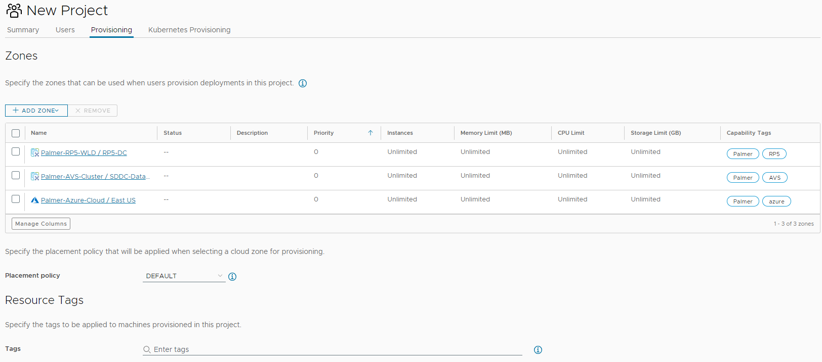
- Tags in the above example will be assigned to any resources created in the project. Customers can use project or application names as tags here. NOTE: The tag ‘azure’ cannot be used here since it will apply to resources deployed in Azure Cloud.
- No other configuration items are supplied in this example, click CREATE.
- Click the Design tab, then click “NEW FROM” and select Blank Canvas.
- Provide a name & description, then select the newly created project.
- This example leaves “Share only with this project”, but if the customer intends to make the new template available to other projects or groups, select “All an administrator to share with any project in this organization”.
- Click CREATE.
- Locate “Machine” under “Cloud Agnostic” in the left Resources pane.
- Drag it to an empty section of the canvas.
- Click the newly populated Cloud_Machine and click the Properties tab in the right pane, then click the slider for “Show all properties”.
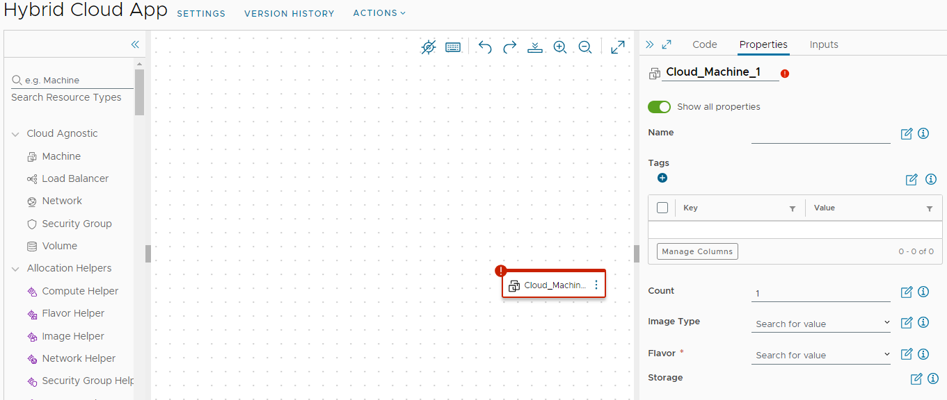
- Provide a name in both locations.
- One is for the canvas, the other is for the VM being deployed.
- Begin typing the image name created in a previous step and select it when the list is populated.
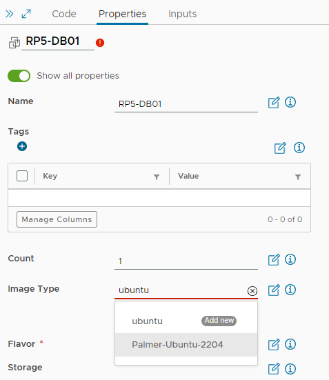
- Type the name of the desired flavor for this VM and select it when the list is populated.
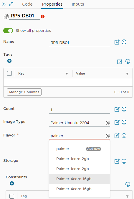
- Scroll down to Maximum Capacity of the disk in GB and enter the maximum desired VMDK size.
- This example sets the capacity to 100 and the boot disk to 16.
- Ensure that the boot disk size enters covers the size of the boot disk of the supplied template in the Image Mapping. For instance, if the template is created with a 64GB disk, the boot disk must be set to a minimum of 64GB.
- Scroll down to Constraints under Cloud Config and provide the tag for the project and location. For instance, this database VM is intended to be deployed in our on-premises zone.
- Click the + icon to add additional constraint tags.
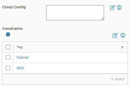
- No other configurations are needed, as the prep work leading to this point will auto select the necessary compute, storage, and network profiles based on the tags supplied as constraints.
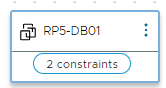
- The Machine icon will now show it has constraints.
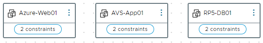
- Repeat this process for two more Cloud Agnostic Machines, assigning the different location constraints for the AVS Cluster and Azure Cloud.
- Once all three are created and have the assigned constraints, the canvas should look like the following image:
- Clicking the code tab on the right pane will show the YAML code for this design, which includes the image mappings & flavor mappings, as well as the constraint tags.
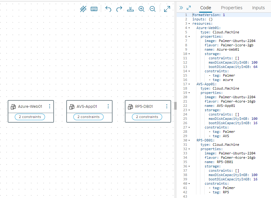
- Click the TEST button to validate all settings and constraints can be met.
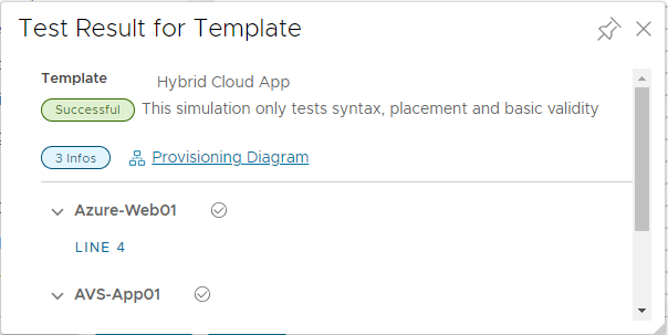
- Click “Provisioning Diagram” to see the flow of how Aria Automation will deploy each machine and which location.
- Each machine can be selected by clicking the “MACHINE ALLOCATION” button below Request Details.
- Each machine diagram will map to the desired cloud zone.
- Click CLOSE, then navigate to the Design tab and click the name of the newly created design.
- Click VERSION, provide a desired version number, a description, and what this version consists of in the Change Log.
- Check the box Release box to make the design available to other users.
- Click the Deploy button, select Create a new deployment, provide a deployment name & description.
- Clear “Current Draft” in Template Version and type the version number from the previous step.
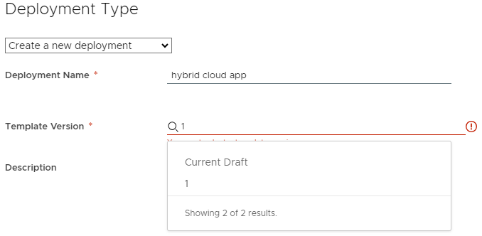
- Click DEPLOY and monitor the deployment progress in the Resources tab under Deployments.
Lessons Learned other Considerations
vSphere ESXi Image Builder is finicky and requires a very specific version of python to be installed. Through testing it was determined to use the specific version outlined in this Deployment Guide. The process outlined in this guide is meant to be for this specific use-case and may very, depending on the environment.
It was discovered that deploying Lenovo XClarity Administrator without initially configuring the interface for operating system image management and deployment until after the 4.0.3 GA fix made the process and feedback very clear. Updating the interface for the operating system image management and deployment during the initial setup wizard may result in the LXCA appliance becoming unresponsive for up to 15 minutes without any indication of processes in the background. The 4.0.3 GA fix is intended to fix this unresponsiveness.
When downloading the ESXi offline bundle for the specific VCF version, check the OEM section to see if a Lenovo-supplied ESXi image exists for build 21424296. If one does exist, that ISO can be imported into LXCA and used for Operating System Deployment, thus skipping the Image Builder section. At the time of this writing, there was not a Lenovo-supplied OEM ISO for build 21424296, thus the need to create one with Image Builder.
DO NOT apply a vLCM image to any pre-existing clusters inside vCenter, as this may result in the inability to apply ESXi upgrades in the future. Please see the following: https://kb.vmware.com/s/article/93220
In VMware Aria, the tag ‘azure’ is reserved for use by Microsoft, thus that tag name cannot be assigned to any resources deployed within Azure Cloud. However, the ‘azure’ tag can be assigned to components within VMware Aria to correlate profiles, mappings, and cloud zones.
Additional Resources/References
VMware Cloud Foundation Holodeck Toolkit
Should customers want to test deploying VCF in an isolated environment, allowing them to get hands-on experience before doing the full deployment, VMware Cloud Foundation Holodeck Toolkit is a fantastic opportunity deploy in an non-impactful way to understand the behavior of all components involved. To learn more about VCF Holodeck Toolkit, see the following link: https://core.vmware.com/introducing-holodeck-toolkit
Additional Links
Upgrade Guide - https://core.vmware.com/resource/upgrade-guide-modernize-your-it-infrastructure-hybrid-cloud-solutions-lenovo-and-vmware
VMware Cloud Foundation - https://www.vmware.com/products/cloud-foundation.html
Lenovo ThinkAgile VX Series - https://www.lenovo.com/us/en/servers-storage/sdi/thinkagile-vx-series/
Lenovo ThinkSystem DM5000H Unified Hybrid Storage Array - https://lenovopress.lenovo.com/lp0885-lenovo-thinksystem-dm5000h-unified-hybrid-storage-array
vSphere Lifecycle Manager Image Management - https://docs.vmware.com/en/VMware-Cloud-Foundation/4.5/vcf-admin/GUID-916CA16B-A297-46AB-935A-23252664F124.html
Microsoft Azure VMware Solution - https://azure.microsoft.com/en-us/products/azure-vmware
VMware Aria Operations - https://www.vmware.com/products/aria-operations.html
VMware Aria Automation - https://www.vmware.com/products/aria-automation.html
Author
Luke Huckaba, VCIX-NV & vExpert, is a Solutions Architect on the Partner Solutions Engineering team in VMware’s Office of the CTO. Luke has over 20 years of experience in IT, more than half of which has been focused on large-scale enterprise VMware solutions. He’s spent the last several years working with large enterprise customers designing resilient multi-cloud VMware solutions that span multiple datacenters and managed service providers, while being deployed across multiple geographic locations.