
vSAN 2-node Cluster Guide
Introduction
A VMware vSAN 2-node cluster is a specific configuration implemented in environments where a minimal hardware footprint is a key requirement. It is designed to minimize the cost and complexity of computing and storage infrastructure at edge locations such as retail stores, branch offices, manufacturing plants, distribution warehouses, etc. In addition to edge deployments, the 2-node configurations can be used for small isolated instances, one-off projects, and small DR solutions. The 2-node configuration has numerous uses that can supplement core infrastructure, it is not limited to just edge solutions.

vSAN documentation provides step-by-step guidance on deploying and configuring vSAN, including 2-node clusters. This guide provides additional information for designing, configuring, and operating a vSAN 2-node cluster.
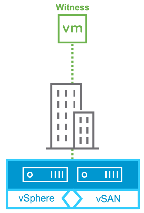
A vSAN 2-node cluster includes deploying a vSAN witness host virtual appliance from an OVA template. The two physical hosts running workloads are commonly deployed at an edge or remote office location. These two hosts are connected using a network switch for North-South traffic in the same location. One of the unique capabilities of a 2-node vSAN is connecting the vSAN network directly between the two hosts without a switch for East-West traffic between nodes. This enables customers to deploy all-flash vSAN in both an vSAN Original Storage Architecture (OSA) or the new vSAN Express Storage Architecture (ESA) without the need for 10 Gb or higher switches. All the vSAN data traffic can be directed across the direct network connections between the hosts while regular VM traffic can utilize a slower standard network switch. This reduces the overall cost for a small vSAN cluster while maintaining the high performance of an all-flash config. Note, that you do not have to use an all-flash config with the 2-node, both hybrid and all-flash deployments are supported.
A vSAN witness host provides a quorum for the two nodes in the cluster as it is located at a different location, such as a primary data center. The connection between the physical hosts and the vSAN witness host requires minimal bandwidth, <500ms. A typical WAN connection is often sufficient for communications between the physical hosts and the vSAN witness host.
Each 2-node deployment before vSAN 7 Update 1 required a dedicated witness appliance. vSAN 7 Update 1 introduced a shared witness host that supports multiple 2-node clusters. Up to 64 2-node clusters can share a witness host. This enhancement simplifies design and eases management and operations. With the release of vSAN ESA, there are now two witness host types, OSA and ESA. vSAN OSA and ESA architectures cannot share the same witness. You must only use the respective witness for that specific architecture. Both are available for download in your customer connect portal.
By default, virtual machines deployed to a vSAN 2-node cluster synchronously mirror (RPO=0, FTT1) the virtual machine data on both hosts for redundancy. Virtual machine data is not stored on the vSAN witness host. Only metadata is stored in the witness host to establish a quorum and ensure data integrity if one of the physical nodes is offline. If a physical node fails, the mirrored copy of the virtual machine data remains accessible on the other physical host. vSAN works with vSphere HA to restart virtual machines previously running on the failed host. This integration between vSphere HA and vSAN automates recovery and minimizes downtime due to hardware failures.
Concepts in vSAN 2-node Clusters
The Witness Host
vSAN Witness Host Purpose
The vSAN Witness Host is a virtual appliance running ESXi. It contains vSAN metadata to ensure data integrity and establish a quorum in case of a physical host failure so that vSAN data remains accessible. The vSAN Witness Host must have connectivity to both vSAN physical nodes in the cluster.
Updating the vSAN Witness Appliance
The vSAN Witness Appliance can easily be maintained/patched using vSphere Lifecycle Manager like physical vSphere hosts. Deploying a new vSAN Witness Appliance is not required when updating or patching vSAN hosts. Normal upgrade mechanisms are supported on the vSAN Witness Appliance. The vSAN witness host should be upgraded first to maintain backward compatibility.
Important: Do not upgrade the on-disk format of the vSAN witness host until all physical hosts have been upgraded.
Read Locality in vSAN 2 Node Clusters
In traditional vSAN clusters, a virtual machine’s read operations are distributed across all replica copies of the data in the cluster. In the case of a policy setting of NumberOfFailuresToTolerate =1, which results in two copies of the data, 50% of the reads will come from replica1, and 50% will come from replica2. In the case of a policy setting of NumberOfFailuresToTolerate =2 in non-stretched vSAN clusters, results in three copies of the data, 33% of the reads will come from replica1, 33% of the reads will come from replica2, and 33% will come from replica3.
In a vSAN 2-node clusters, 100% of reads occur in the site (host) the VM resides on. This aligns with the behavior of vSAN Stretched Clusters. Read locality overrides the NumberOfFailuresToTolerate=1 policy’s behavior to distribute reads across the components.
This is not significant to consider in All-Flash configurations but should be considered in Hybrid vSAN configurations. To understand why, it is important to know how read and write operations behave in 2-node Virtual SAN configurations.

Writes Are Synchronous
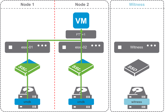
In vSAN, write operations are always synchronous. The image of a Hybrid vSAN cluster shows that writes are being written to Node 1 and Node 2, with Metadata updates being written to the vSAN Witness Host. This is due to a Number of Failures to Tolerate policy of 1.
Notice the blue triangle in the cache devices? That’s 30% of the cache device being allocated as the write buffer. The other 70% of the cache device is green, demonstrating the read cache. It is important to note that All-Flash vSAN clusters do not use the cache devices for read caching.
Writes go to the write buffer on both Nodes 1 and 2. This is always the case because writes occur on both nodes simultaneously.

Default Stretched Cluster / 2-node Read Behavior.
By default, reads are only serviced by the host that the VM is running on.
The image shows a typical read operation. The virtual machine is running on Node 1, and all reads are serviced by the cache device of Node 1’s disk group.
By default, reads do not traverse to the other node. This behavior is the default in 2-node configurations, as they are mechanically similar to Stretched Cluster configurations. This behavior is preferred when the latency between sites is at the upper end of the supported boundary of 5ms round-trip-time (RTT).
This is advantageous in situations where the two sides of a Stretched Cluster are connected by an inter-site link, because it removes additional overhead of reads traversing the inter-site link.

2-node Reads after vMotion
Read operations after a vMotion, are going to behave differently.
Because the cache has not been warmed on the host the virtual machine is now running on, reads will have to occur on the capacity drives as the cache is warmed.
The image shows only part of the cache device as green, indicating that as reads occur, they are cached in the read cache of the disk group.
The process of invoking a vMotion could be from various DRS events, such as putting a host in maintenance mode or balancing workloads. The default Stretched Cluster recommendation, is to keep virtual machines on one site or another, unless there is a failure event.

2 Node Reads after a Disk Failure
Read operations after a disk failure, are going to behave similarly to those of a vMotion. A single disk in the disk group has failed in the image on the right. Reads are going to come from Node 2, and the cache device on Node 2 is going to start caching content from the virtual machine’s disk.
Since only a capacity device failed, and there are others still contributing to the capacity, reads will also traverse the network, as data is rewritten to one of the surviving capacity devices on Node 1 if there is sufficient capacity.
Once data has been reprotected on Node 1, the cache will have to rewarm on Node 1 again.

2 Node Reads after a Cache Device/Disk Group Failure
Read operations after a disk group failure are also going to behave like that of a disk failure.
In configurations where the host with a failed disk group has an additional disk group, rebuilds will occur on the surviving disk group provided there is capacity.
In hosts with a single disk group, rebuilds will not occur, as the disk group is unavailable.

What can be done to prevent the need for rewarming the read cache?
There is an advanced setting which will force reads to always be serviced by both hosts.
The vSAN “DOMOwnerForceWarmCache” setting can be configured to force reads on both Node 1 and Node 2 in a 2-Node configuration.
Forcing the cache to be read across Stretched Cluster sites is not recommended because additional read latency can be introduced.
vSAN 2-node configurations are typically in a single location, directly connected or connected to the same switch, just as a traditional vSAN deployment.
When DOMOwnerForceWarmCache setting is True (1), it will force reads across all mirrors to most effectively use cache space. This means reads would occur across both nodes in a 2-node config.
When it is False (0), site locality is in effect, and reads are only occurring on the site the VM resides on.
In short, DOM Owner Force Warm Cache:
- Doesn’t apply to traditional vSAN clusters
- Stretched Cluster configs with acceptable latency & site locality enabled – Default 0 (False)
- 2-node (typically low, or very low latency) – Modify 1 (True)
Not only does this help in the event of a virtual machine moving across hosts, which would require the cache to be rewarmed, but it also allows reads to occur across both mirrors, distributing the load more evenly across both hosts.
The vSAN 6.7 Advanced Options UI presents an option to deactivate or reactivate Read Locality, but only for 2-node or Stretched Clusters:

This setting can be retrieved or modified ESXi command line on each host as well:
- To check the status of Read Locality, run the following command on each ESXi host:
esxcfg-advcfg -g /VSAN/DOMOwnerForceWarmCacheIf the value is 0, then Read Locality is set to the default (enabled).
- To deactivate Read Locality in a 2-node clusters, run the following command on each ESXi host:
esxcfg-advcfg -s 1 /VSAN/DOMOwnerForceWarmCache
PowerCLI can also be used to deactivate or reactivate Read Locality. Here is a one-liner PowerCLI script to deactivate or reactivate Read Locality for both hosts in the 2-node cluster.
| # Value of 1 to deactivate, a value of 0 to reactivate Get-Cluster -Name <ClusterName> | Get-VMHost | Get-AdvancedSetting -Name "VSAN.DOMOwnerForceWarmCache" | Set-AdvancedSetting -Value "0" -Confirm:$False |
Forcing reads to be read across both nodes in cases where the Number of Failures to Tolerate policy is 1 can prevent having to rewarm the disk group cache in cases of vMotions, host maintenance, or device failures.
Client Cache
VMware vSAN 6.2 introduced Client Cache, a mechanism that allocates 0.4% of host memory, up to 1GB, as an additional read cache tier. Virtual machines leverage the Client Cache of the host they are running on. Client Cache is not associated with Stretched Cluster read locality, and runs independently.
Witness Traffic Separation (WTS)
By default, when using vSAN 2 Node configurations, the Witness VMkernel interface tagged for vSAN traffic must have connectivity with each vSAN data node's VMkernel interface tagged with vSAN traffic.
In vSAN 6.5, an alternate VMkernel interface can be designated to carry traffic destined for the Witness rather than the vSAN tagged VMkernel interface. This feature allows for more flexible network configurations by allowing for separate networks for node-to-node and node-to-witness traffic.
2 Node Direct Connect
This Witness Traffic Separation provides the ability to directly connect vSAN data nodes in a 2 Node configuration. Traffic destined for the Witness host can be tagged on an alternative interface from the directly connected vSAN tagged interface.

In the illustration above, the configuration is as follows:
- Host 1
- vmk0 - Tagged for Management Traffic
- vmk1 - Tagged for Witness Traffic - This must* be done using esxcli vsan network ip add -i vmk1 -T=witness
- vmk2 - Tagged for vSAN Traffic
- vmk3 - Tagged for vMotion Traffic
- Host 2
- vmk0 - Tagged for Management Traffic
- vmk1 - Tagged for Witness Traffic - This must* be done using esxcli vsan network ip add -i vmk1 -T=witness
- vmk2 - Tagged for vSAN Traffic
- vmk3 - Tagged for vMotion Traffic
- vSAN Witness Appliance
- vmk0 - Tagged for Management Traffic***
- vmk1 - Tagged for vSAN Traffic****
*Enabling Witness Traffic is not available from the vSphere Web Client.
**Any VMkernel port, not used for vSAN Traffic, can be used for Witness Traffic. In a more simplistic configuration, the Management VMkernel interface (vmk0) could be tagged for Witness Traffic. The VMkernel port used, will be required to have connectivity to the vSAN Traffic tagged interface on the vSAN Witness Appliance.
***The vmk0 VMkernel Interface, which is used for Management traffic may also be used for vSAN Traffic. In this situation, vSAN Traffic must be unchecked from vmk1.
****The vmk1 VMkernel interface must not have an address that is on the same subnet as vmk0. Because vSAN uses the default tcp/ip stack, in cases where vmk0 and vmk1 are on the same subnet, traffic will use vmk0 rather than vmk1. This is detailed in KB 2010877 . Vmk1 should be configured with an address on a different subnet than vmk0.
The ability to connect 2 Nodes directly removes the requirement for a high speed switch. This design can be significantly more cost effective when deploying tens or hundreds of 2 Node clusters.
vSAN 2 Node Direct Connect was announced with vSAN 6.5, and is available with vSAN 6.5 or higher and 6.6, 6.5, and 6.2*. *6.2 using vSphere 6.0 Patch 3 or higher without an RPQ
vSAN File services support for 2-node cluster
File services can be used in vSAN stretched clusters as well as vSAN 2-Node topologies, which can make it ideal for those edge locations also in need of a file server. File services in vSAN 7 Update 2 support Data-in-Transit encryption, as well as the space reclamation technique known as UNMAP. File services for vSAN 7 Update 2 have a snapshotting mechanism for point-in-time recovery of files. This mechanism, available through API, allows our backup partners to build applications to protect file shares in new and interesting ways. And finally, vSAN 7 Update 2 optimizes some of the metadata handling and data path for more efficient transactions, especially with small files. For more details go to stretched cluster guide document.
vSAN 8 using Express Storage architecture does not support vSAN File services for a 2-node cluster.
Nested fault domains for 2 Node cluster
This new feature is built on the concept of fault domains, where each host or a group of hosts can store redundantly VM object replicas. In a 2 Node cluster configuration, fault domains can be created on a per disk-group level for vSAN OSA and per disk using vSAN ESA, enabling disk-group or disk based data replication. Meaning, each of the two data nodes can host multiple object replicas. Thanks to that secondary level of resilience the 2 Node cluster can ensure data availability in the event of more than one device failure. For instance, one host failure and an additional device or disk group failure, will not impact the data availability of the VMs having a nested fault domain policy applied. The vSAN demo below shows the object replication process across disk groups and across hosts.
Please refer to the "Nested fault domains for 2 Node cluster "sub-section, under the Failure scenarios section in this document for more details.
In vSAN 8 using Express Storage Architecture (ESA), changes to support Nested fault domains for 2-node clusters do not affect existing functionality. However, there are changes needed in the backend to extend support to use Storage Pool disks as fault domains for vSAN ESA.
To summarize:
- In vSAN OSA, object components are placed on available host disk groups to satisfy the policy
- In vSAN ESA, object components are placed on individual disks of a Storage Pool of a host to satisfy the policy
Prerequisites
VMware vCenter Server
A vSAN 2 Node Cluster configuration can be created and managed by a single instance of VMware vCenter.
A Witness Host
In a vSAN 2 Node Cluster, the Witness components are only ever placed on the vSAN Witness Host. Either a physical ESXi host or the vSAN Witness Appliance provided by VMware can be used as a vSAN Witness.
If a vSAN Witness Appliance is used for the Witness, it will not consume any of the customer’s vSphere or vSAN licenses. A physical ESXi host that is used as a vSAN Witness Host will need to be licensed accordingly, as this can still be used to provision virtual machines should a customer choose to do so.
The vSAN Witness appliance, when added as a host to vCenter will have a unique identifier in the vSphere UI to assist with identification. There will be two views of the host when using the witness appliance, one as a virtual machine and one as a vSphere host.
In vSphere 7 it is shown as a “blue” host, as highlighted below.

In vSphere 8 the witness host has a small eye on the host icon.

It is important that the vSAN Witness Host is NOT added to the vSAN cluster. The vSAN Witness Host is selected during the creation of a vSAN 2 Node Cluster. A vSAN Witness Host, regardless of whether it is a Physical host or a vSAN OSA or ESA Witness Appliance, cannot be added to a vSphere Cluster.
Note: This is only visible when the vSAN Witness Appliance is deployed. If a physical host is used as a vSAN Witness Host, then it does not change its appearance in the web client. A dedicated vSAN Witness Host is required for each 2 Node Cluster.
Networking and Latency Requirements
When vSAN is deployed in a 2 Node Cluster there are certain networking requirements that must be adhered.
Layer 2 and Layer 3 Support
Both Layer 2 (same subnet) and Layer 3 (routed) configurations are used in a recommended vSAN 2 Node Cluster deployment.
- VMware recommends that vSAN communication between the vSAN nodes be over L2.
- VMware recommends that vSAN communication between the vSAN nodes and the Witness Host is
- Layer 2 for configurations with the Witness Host in the same site
- Layer 3 for configurations with the Witness Host in an alternate site.
vSAN traffic between nodes is multicast for versions 6.5 and previous, while unicast is used for version 6.6 or later. Witness traffic between each node in a 2 Node cluster and the Witness Host is unicast.
vSAN Node to Witness Network Latency
This refers to the communication between vSAN hosts and the Witness Host/Site.
In typical 2 Node configurations, such as Remote Office/Branch Office deployments, this latency or RTT is supported up to 500msec (250msec one-way).
The latency to the Witness Host is dependent on the number of objects in the cluster.
vSAN Node to Witness Network Bandwidth
Bandwidth between vSAN Nodes hosting VM objects and the Witness Host is dependent on the number of objects residing on vSAN. It is important to size data site to witness bandwidth appropriately for both availability and growth. A standard rule is 2Mbps for every 1000 components on vSAN. Because vSAN nodes have a maximum number of 9000 components per host, the maximum bandwidth requirement from a 2 Node cluster to the Witness Host supporting it, is 18Mbps.
Please refer to the Design Considerations section of this guide for further details on how to determine bandwidth requirements.
Inter-Site MTU Consistency
Knowledge Base Article 2141733 details a situation where data nodes have an MTU of 9000 (Jumbo Frames) and the vSAN Witness Host has an MTU of 1500. The vSAN Health Check looks for a uniform MTU size across all VMkernel interfaces that are tagged for traffic related to vSAN, and reports any inconsistencies. It is important to maintain a consistent MTU size across all vSAN VMkernel interfaces on data nodes and the vSAN Witness Host in a vSAN 2 Node cluster to prevent traffic fragmentation.
As KB 2141733 indicates, the corrective actions are either to reduce the MTU from 9000 on the data node VMkernel interfaces, or increase the MTU value on the vSAN Witness Host's VMkernel interface that is tagged for vSAN Traffic. Either of these are acceptable corrective actions.
The placement of the vSAN Witness Host will likely be the deciding factor in which configuration will be used. Network capability, control, and cost to/from the vSAN Witness Host as well as overall performance characteristics on data nodes are items to consider when making this design decision.
In situations where the vSAN Witness Host VMkernel interface tagged for vSAN traffic is not configured to use Jumbo Frames (or cannot due to underlying infrastructure), VMware recommends that all vSAN VMkernel interfaces use the default MTU of 1500.
As a reminder, there is no requirement to use Jumbo Frames with VMkernel interfaces used for vSAN.
Multiple vSAN Witness Hosts sharing the same VLAN
For customers who have implemented multiple 2 Node vSAN deployments, a common question is whether the Witness traffic from each of the remote sites requires its own VLAN.
The answer is no.
Multiple 2 Node vSAN deployments can send their witness traffic on the same shared VLAN.
Configuration Minimums and Maximums
Virtual Machines Per Host
Witness Host
There is a maximum of 1 vSAN Witness Host per vSAN 2 Node Cluster.
The vSAN Witness Host requirements are discussed in the Design Considerations section of this guide.
VMware provides a fully supported vSAN Witness Appliance, in the Open Virtual Appliance (OVA) format. This is for customers who do not wish to dedicate a physical ESXi host as the witness. This OVA is essentially a pre-licensed ESXi host running in a virtual machine, and can be deployed on a physical ESXi host at the 3rd site or host.
vSAN Storage Policies
Number of Failures To Tolerate (FTT) - Pre-vSAN 6.6
Primary Number of Failures To Tolerate (PFTT) - vSAN 6.6 and forward
The FTT/PFTT policy setting, has a maximum of 1 for objects.
In Pre-vSAN 6.6 2 Node Clusters FTT may not be greater than 1. In vSAN 6.6 or higher 2 Node Clusters, PFTT may not be greater than 1. This is because 2 Node Clusters are comprised of 3 Fault Domains.
Failure Tolerance Method (FTM)
Failure Tolerance Method rules provide object protection with RAID-1 (Mirroring). Mirroring is the only FTM rule that can be satisfied, due to the 3 fault domains present. This means that data is Mirrored across both sites.
Affinity
Affinity rules are used when the PFTT rule value is 0. This rule has 2 values, Preferred or Secondary. This determines which site an Affinity based vmdk would reside on.
Other Policy Rules
Other policy settings are not impacted by deploying vSAN in a 2 Node Cluster configuration and can be used as per a non-stretched vSAN cluster.
Fault Domains
Design Considerations
Cluster Compute Resource Utilization
For full availability, VMware recommends that customers should be running at 50% of resource consumption across the vSAN 2 Node Cluster. In the event of a node failure, all of the virtual machines could be run on the surviving node.
VMware understands that some customers will want to run levels of resource utilization higher than 50%. While it is possible to run at higher utilization in each site, customers should understand that in the event of failure, not all virtual machines will be restarted on the surviving node.
| vSAN Version | Protection | FTT/PFTT | FTM | SFTT | Capacity Required in Preferred Site | Capacity Required in Secondary Site | Capacity Requirement |
|---|---|---|---|---|---|---|---|
| 6.1 and higher | Across Sites Only | 1 | Mirroring | NA | 100% | 100% | 200% |
Network Design Considerations
2 Node vSAN Network Design Considerations
Sites
A vSAN 2 Node Cluster typically runs in a single site, with the vSAN Witness Host residing in an alternate location or on an alternate host in the same site.
vSAN Data nodes
- Preferred Node - Specified to be the primary owner of vSAN objects. This is an important designation specifically in cases of connectivity disruptions.
- Secondary Node - Backup owner of vSAN objects.
Witness Site - Contains vSAN Witness host - Could be in a different site, or the small site as the 2 Node cluster.
- Maintains Witness Component data from Preferred/Secondary sites when applicable
Connectivity and Network Types
| Preferred Host | Secondary Host | Witness Site | |
| Management Network to vCenter | Layer 2 or 3 | Layer 2 or 3 | Layer 2 or 3 |
| Management Network to Alternate Host | Typically Layer 2 | Typically Layer 2 | |
| VM Network | Typically Layer 2 | Typically Layer 2 | No requirement for VM Network. Running VMs on the vSAN Witness Appliance is not supported. Running VMs on a Physical Witness Host is supported. |
| vMotion Network | Typically Layer 2 vMotion is not required between this Data site & the Witness Site |
Typically Layer 2 vMotion is not required between this Data site & the Witness Site |
There is no requirement for vMotion networking to the Witness site. |
| vSAN Network | Layer 2 Multicast: vSAN 6.1-6.5 Unicast: vSAN 6.6+ |
Layer 2 Multicast: vSAN 6.1-6.5 Unicast: vSAN 6.6+ |
|
| Witness Traffic Using WTS & vSAN Witness Offsite |
To the vSAN Witness Site: Layer 3
|
To the vSAN Witness Site: Layer 3
|
To the Data Site: Layer 3 |
| Witness Traffic Using WTS & vSAN Witness Locally | To the vSAN Witness: Layer 2 or 3 | To the vSAN Witness: Layer 2 or 3 | To the vSAN Nodes: Layer 2 or 3 |
Note that vSAN using RDMA is not supported in a 2 node topology.
Port Requirements
VMware vSAN requires these ports to be open, both inbound and outbound:
| Port | Protocol | Connectivity To/From | |
| vSAN Clustering Service | 12345, 23451 | UDP | vSAN Hosts |
| vSAN Transport | 2233 | TCP | vSAN Hosts |
| vSAN VASA Vendor Provider | 8080 | TCP | vSAN Hosts and vCenter |
| vSAN Unicast Agent (to Witness Host) | 12321 | UDP | vSAN Hosts and vSAN Witness Appliance |
TCP/IP Stacks, Gateways, and Routing
TCP/IP Stacks
At this time, the vSAN traffic does not have its own dedicated TCP/IP stack. Custom TCP/IP stacks are also not applicable for vSAN traffic.
Default Gateway on ESXi Hosts
ESXi hosts come with a default TCP/IP stack. As a result, hosts have a single default gateway. This default gateway is associated with the Management VMkernel interface (typically vmk0).
It is a best practice to implement separate storage networking, in this case vSAN networking, on an alternate VMkernel interface, with alternate addressing.
vSAN networking uses the same TCP/IP stack as the Management VMkernel interface. If the vSAN Data Network were to attempt to use a Layer 3 network, static routing would be need to be added for the VMkernel interfaces tagged for vSAN Traffic.
The addition of Witness Traffic separation allows vSAN interfaces to be directly connected across hosts with communication to the vSAN Witness handled by an alternate interface that has traffic tagged as "Witness" traffic.
Communication with the vSAN Witness via an alternate VMkernel interface can be performed by using a separate VMkernel interface, or the Management interface, as long as the interface used has traffic tagged as "Witness Traffic".
It is important to remember that vSAN uses the same TCP/IP stack as the Management interface, and therefore if an alternate interface is used, static routing must be in place for the vSAN node to properly communicate with the vSAN Witness Host
The Witness Host on the Witness Site will require a static route added so that requests to reach the 2 Node Cluster are routed out the WitnessPg VMkernel interface
Static routes are added via the esxcli network ip route or esxcfg-route commands. Refer to the appropriate vSphere Command Line Guide for more information.
Caution when implementing Static Routes: Using static routes requires administrator intervention. Any new ESXi hosts that are added to the cluster at either site 1 or site 2 needed to have static routes manually added before they can successfully communicate to the witness, and the other data site. Any replacement of the witness host will also require the static routes to be updated to facilitate communication to the data sites.
Sample configuration using Witness Traffic Separation using a dedicated VMkernel Interface on each ESXi Host
In the illustration below, each vSAN Host's vmk1 VMkernel interface is tagged with "witness" traffic. Each vSAN Host must have a static route configured for vmk1 able to properly access vmk1 on the vSAN Witness Host, which is tagged with "vsan" traffic. The vmk1 interface on the vSAN Witness Host must have a static route configured to be able to properly communicate with vmk1 on each vSAN Host. This is a supported configuration.

Sample configuration using Witness Traffic Separation using only the Management VMkernel Interface on each ESXi Host
In the illustration below, each vSAN Host's vmk0 VMkernel interface is tagged with both "Management" and "witness" traffic. The vSAN Witness Host has the vmk0 VMkernel interface tagged with both "Management" and "vsan" traffic. This is also a supported configuration.

Sample misconfiguration with vSAN Witness vmk0/vmk1 on the same subnet
In this illustration, the vmk0 and vmk1 VMkernel interfaces are on the same network. Vmk1 is tagged for "vsan" traffic and vmk0 is tagged for "Managment" traffic. Because vSAN uses the default TCP/IP stack, vSAN traffic does not properly flow form vmk1, which is tagged for "vsan" traffic, but rather from vmk0, which is NOT tagged for "vsan" traffic. This causes an error with the vSAN Health Check indicating that the vSAN Witness Host does not have proper tagging.

The issue is not unique to vSAN, but rather occurs when using any VMkernel interfaces using the default TCP/IP stack. KB Article 2010877 addresses this condition.
Though not represented here, this is also true for the vSAN Data network.
The Role of vSAN Heartbeats
Bandwidth Calculation
As stated in the requirements section, the bandwidth requirement between the two main sites is dependent on workload and in particular the number of write operations per ESXi host. Other factors such as read locality not in operation (where the virtual machine resides on one site but reads data from the other site) and rebuild traffic, may also need to be factored in.
Requirements Between 2 Node vSAN and the Witness Site
Hosts designated as a vSAN Witness Host do not maintain any VM data, but rather only component metadata, the requirements are much smaller than that of the backend vSAN data network.
Virtual Machines on vSAN are comprised of multiple objects, which can potentially be split into multiple components, depending on factors like policy and size. The number of components on vSAN has a direct impact on the bandwidth requirement between the data sites and the witness.
The required bandwidth between the vSAN Witness Host and each node is equal to ~1138 B x Number of Components /5s
1138 B x NumComp / 5 seconds
The 1138 B value comes from operations that occur when the Preferred Site goes offline, and the Secondary Site takes ownership of all of the components.
When the Preferred Node goes offline, the Secondary Node becomes the Primary Node. The vSAN Witness Host sends updates to the new Primary node followed by the new Primary node replying to the vSAN Witness Host as ownership is updated.
The 1138 B requirement for each component comes from a combination of a payload from the vSAN Witness Host to the backup agent, followed by metadata indicating that the Preferred Site has failed.
In the event of a Preferred Node failure, the link must be large enough to allow for the cluster ownership to change, as well ownership of all of the components within 5 seconds.
Witness to Site Examples
Workload 1
With a VM being comprised of
- 3 objects {VM namespace, vmdk (under 255GB), and vmSwap}
- Failure to Tolerate of 1 (FTT=1)
- Stripe Width of 1
Approximately 25 VMs with the above configuration would require the vSAN Witness Host to contain 75 components.
To successfully satisfy the Witness bandwidth requirements for a total of 75 components on vSAN, the following calculation can be used:
Converting Bytes (B) to Bits (b), multiply by 8
B = 1138 B * 8 * 75 / 5s = 136,560 Bits per second = 136.56 Kbps
VMware recommends adding a 10% safety margin and round up.
B + 10% = 136.56 Kbps + 13.656 Kbps = 0.150 Kbps
With the 10% buffer included, a standard rule can be stated that for every 1,000 components, 2 Mbps is appropriate.
Workload 2
With a VM being comprised of
- 3 objects {VM namespace, vmdk (under 255GB), and vmSwap}
- Failure to Tolerate of 1 (FTT=1)
- Stripe Width of 2
- 2 Snapshots per VM
Approximately 25 VMs with the above configuration would require up to 250 components to be stored on the vSAN Witness Host.
To successfully satisfy the Witness bandwidth requirements for 250 components on vSAN, the resulting calculation is:
B = 1138 B * 8 * 250 / 5s = 455,200 Bits per second = 455.2 Kbps
B + 10% = 455.2 Kbps + 45.52 Kbps = 500.7 Kbps
Using the general equation of 2Mbps for every 1,000 components, (NumComp/1000) X 2Mbps, it can be seen that 250 components does in fact require 0.5 Mbps.
Using the vSAN Witness Appliance as a vSAN Witness Host
VMware vSAN 2 Node Clusters require a vSAN Witness Host.
This section will address using the vSAN Witness Appliance as a vSAN Witness Host. The vSAN Witness Appliance is available in an OVA (Open Virtual Appliance) format from VMware. The vSAN Witness Appliance does need to reside on a physical ESXi host.
Minimal Requirements to Host the vSAN Witness Appliance
- The vSAN Witness Appliance must on an ESXi 5.5 or greater VMware host.
- The ESXi 5.5 or greater host must meet the minimum requirements for the vSAN Witness Host for the version of vSAN 2 Node that the vSAN Witness Appliance will support.
- Networking must be in place that allows for the vSAN Witness Appliance to properly communicate with the vSAN 2 Node Cluster.
Where can the vSAN Witness Appliance run?
In addition to the minimal requirements for hosting the vSAN Witness Appliance, several supported infrastructure choices are available:
- On a vSphere environment backed with any supported storage (vmfs datastore, NFS datastore, vSAN Cluster)
- On vCloud Air/OVH backed by a supported storage
- Any vCloud Air Network partner-hosted solution
- On a vSphere Hypervisor (free) installation using any supported storage (vmfs datastore or NFS datastore)
Support Statements specific to placement of the vSAN Witness Appliance on a vSAN cluster:
- The vSAN Witness Appliance is supported running on top of another non-Stretched vSAN cluster.
- The vSAN Witness Appliance is supported on a Stretched Cluster vSAN for another vSAN 2 Node cluster.
- vSAN 2-node cluster hosting witness for another vSAN 2-node cluster witness, and vice versa, is not recommended and requires an RPQ.
The next question is how to implement such a configuration, especially if the witness host is on a public cloud? How can the interfaces on the hosts in the data sites, which communicate to each other over the vSAN network, communicate to the witness host?
CPU Requirements
The vSAN Witness Appliance is a virtual machine that has special vSphere installation that is used to provide quorum/tiebreaker services for a 2 Node vSAN Cluster. The underlying CPU architecture must be supported by the vSphere installation inside the vSAN Witness Appliance.
As an example, a vSphere/vSAN 6.7 2 Node vSAN Cluster will require a vSAN Witness Appliance that is running vSphere 6.7. The ESXi host that the vSAN Witness Appliance runs on top of, could run any version of vSphere 5.5 or higher. With vSphere/vSAN 6.7 having different CPU requirements, the ESXi host that the vSAN Witness Appliance runs on must support the CPU requirements of vSphere 6.7, regardless of the version of vSphere the ESXi host is running.
In cases where a vSAN Witness Appliance is deployed to an ESXi host that does not meet the CPU requirements, it may be deployed, but not powered on. The vSAN Witness Appliance, patched like a normal vSphere Host, cannot be upgraded to vSphere 6.7 if the underlying CPU does not support vSphere 6.7.
This consideration is important to take into account when upgrading 2 Node vSAN Clusters. The vSAN Witness is a critical part of the patching and upgrade process. It is strenuously recommended by VMware to keep the vSAN Witness version consistent with the vSphere version of the 2 Node vSAN Cluster.
Networking
The vSAN Witness Appliance contains two network adapters that are connected to separate vSphere Standard Switches (VSS).
The vSAN Witness Appliance Management VMkernel is attached to one VSS, and the WitnessPG is attached to the other VSS. The Management VMkernel (vmk0) is used to communicate with the vCenter Server for normal management of the vSAN Witness Appliance. The WitnessPG VMkernel interface (vmk1) is used to communicate with the vSAN Data Nodes. This is the recommended configuration.
Alternatively, the Management VMkernel (vmk0) interface could be tagged to include vSAN traffic as well as Management traffic. In this case, vmk0 would require connectivity to both vCenter Server and the vSAN Witness Network.
A Note About Promiscuous Mode
In many ESXi in a VM environment, there is a recommendation to enable promiscuous mode to allow all Ethernet frames to pass to all VMs that are attached to the port group, even if it is not intended for that particular VM. The reason promiscuous mode is enabled in many ESXi in a VM environment is to prevent a virtual switch from dropping packets for (nested) vmnics that it does not know about on the ESXi in a VM hosts. ESXi in a VM deployments are not supported by VMware other than the vSAN Witness Appliance.
The MAC addresses of the vSAN Witness Appliance's VMkernel interfaces vmk0 & vmk1 are configured to match the MAC addresses of the ESXi host's physical NICs, vmnic0, and vmnic1. Because of this, packets destined for either the Management VMkernel interface (vmk0) or the WitnessPG VMkernel interface, are not dropped.
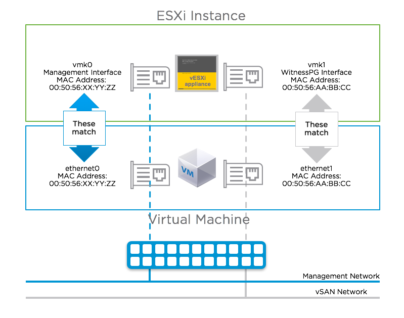
Because of this, promiscuous mode is not required when using a vSAN Witness Appliance.
Since the vSAN Witness Appliance will be deployed on a physical ESXi host the underlying physical ESXi host will need to have a minimum of one VM network preconfigured. This VM network will need to reach both the management network and the vSAN network shared by the ESXi hosts on the data sites. An alternative option that might be simpler to implement is to have two preconfigured VM networks on the underlying physical ESXi host, one for the management network and one for the vSAN network. When the virtual ESXi witness is deployed on this physical ESXi host, the network will need to be attached/configured accordingly.

Using a Physical Host as a vSAN Witness Host
Physical ESXi host used as a vSAN Witness Host:
When using a physical ESXi host as a vSAN Witness Host, the VMkernel interface that will be tagged for "vsan" traffic must have connectivity to the vSAN Data Node VMkernel interace that is tagged for "witness" traffic. This could be over Layer 3, or even over Layer 2 if desired.
If using a physical host as the vSAN Witness Host there are some requirements to consider.
| Requirements | |
| Licensing |
If using a physical host as a vSAN Witness Host, it must be licensed with a valid vSphere license. This does not require the same licensed edition as the vSAN Cluster it is supporting. |
| vSphere Build | If using a physical host as a vSAN Witness Host, it must be running the same build of vSphere as the 2 Node Cluster that it is participating with. |
| Compute & Memory | The minimum specifications required for ESXi meet the minimum requirements for use as a vSAN Witness Host. Minimum requirements for vSphere are dependent on the build of vSphere and can be found in the documentation section for each edition in VMware Documentation: https://www.vmware.com/support/pubs/ |
| Storage | Storage requirements do not change for a physical host being used as a vSAN Witness Host in comparison to the vSAN Witness Appliance. An ESXi boot device, a cache device, and one or more capacity devices are still required.
Required
|
| Other Workloads | If using a physical host as a vSAN Witness Host, it may run other workloads. Because the physical vSAN Witness Host is external to the vSAN Cluster it is contributing to, those workloads will not be part of the vSAN Cluster. The vSAN Disk Group, and the disks it includes, may not be used for those workloads.
*Important consideration: Multiple vSAN Witness Appliances can run on a single physical host. Using vSAN Witness Appliances is typically more cost-effective than dedicating physical hosts for the purpose of meeting the vSAN Witness Host requirement. |
Using the vSAN witness appliance or a physical host as a shared witness.
Overview
VMware vSAN 2-node architecture has always been a perfect solution for organizations that have many small branch offices or retail sites. It is also very beneficial for small businesses and startups who want to avoid the significant up-front costs associated with storage hardware. The shared witness host appliance additionally reduces the amount of physical resources needed at the central site, resulting in a greater level of savings for а large number of 2-node branch office deployments. For example, a topology with 30 remote sites would have previously needed 240 GB of RAM at the central site for the witness host appliance, while using the shared witness model would require 16 GB. One single shared witness can be shared across a maximum of 64 2-node clusters, supporting up to 64, 000 components, and requires at least 6 CPUs, and 32GB memory allocation for the Witness. Additionally, we support a max of 1000 components per 2-node cluster. Build-in checks will monitor if the maximum number of components for a witness in a 2-node cluster has been reached and they would not allow the witness to be converted into a shared witness.
Namely, shared witnesses can be deployed in the same topology scenarios where a standard witness is deployed (e.g. running in a VCPP location), the shared witness can be either a virtual witness host appliance or a physical host.
New UI additions are created to support the shared witness enablement and there is a new health check to cover the non-ROBO cluster with a shared witness.

A couple of conditions should be met before you can enable the shared host appliance architecture:
• As of vSAN 7 U1, the witness node should be upgraded first (to maintain backward compatibility). Upgrading of the witness can be accomplished through VUM but is not supported by vLCM at this time. Alternatively, to upgrading, the witness can be replaced or redeployed. Please refer to the vSAN operations guide to look at the process of replacing a vSAN witness host.
A witness host can be upgraded to version vSAN 7 U1 to become a shared witness or a new host can be deployed and used as a shared witness. If you decide to upgrade your witness host, both the software and the disk format of the witness node should be upgraded before all the other nodes. Once the witness node is upgraded it’ll be able to communicate with the rest of the nodes in the connected clusters that might be of lower version. The witness VM is backward compatible to previous v6 and v7 vSAN clusters, and you may upgrade the disk format version only once upgrading first the vSAN witness VM, then the vSAN cluster. When using a shared witness for vSAN 2-node clusters, the process for upgrading introduces a few additional considerations. See Upgrading 2-node vSAN Clusters from 6.7U3 to 7U1 with a Shared Witness Host for more information. Other design and operation changes for 2-node topologies can be found in the post: New Design and Operation Considerations for vSAN 2-Node Topologies.
• All vSAN clusters participating in a shared witness must use the new on-disk format (ODF) version associated with vSAN 7 U1 (v13).
Ex. If you want to move all your 30 existing 2-node clusters to single shared witness, these are the basic steps to follow:
1. Upgrade the existing witness to version 7 Update 1 or deploy a new one of the same versions.
2. Upgrade the existing clusters to version 7 Update 1.
3. Assign all clusters to the shared witness host or appliance. For OVF sizes and recommendations, you should consult the vSAN Witness Appliance Sizing section in this document.
Limitations
• New witness OVA has been built to meet the increased CPU and memory configuration. A maximum of 1000 components per cluster has been introduced. Please refer to the vSAN Witness Appliance Sizing section in this guide for more details.
- Keep in mind, there is a special consideration when it comes to 2-node clusters with a shared witness host. The on-disk format upgrades in a vSAN environment with multiple 2-node clusters and a shared witness should only be performed once all the hosts sharing the same witness are running the same vSphere/vSAN version. IMPORTANT: Do NOT upgrade the on-disk format of your disks until all hosts sharing the same witness are upgraded to the same vSphere version. You can find more details in the following blog post - "Upgrading vSAN 2-node Clusters with a Shared Witness from 7U1 to 7U2".
• A witness node cannot convert to shared witness if the initial cluster is over the per-cluster component limit.
• Every new cluster using the shared witness option should be below the per-cluster component limit.
• Stretched cluster and data-in-transit encryption are not supported in vSAN 7 Update
vSAN Witness Host Networking Examples
In both options, either a physical ESXi host or vSAN Witness Appliance may be used as vSAN Witness Host or vSAN shred witness host.
Option 1: 2 Node Configuration for Remote Office/Branch Office Deployment using Witness Traffic Separation with the vSAN Witness in a central datacenter
In the use case of Remote Office/Branch Office (ROBO) deployments, it is common to have 2 Node configurations at one or more remote offices. This deployment model can be very cost competitive when running a limited number of virtual machines no longer require 3 nodes for vSAN.

Fig.1 Dedicated witness host.
.png)
Fig.1 Shared witness host.
Management traffic for the data nodes is typically automatically routed to the vCenter server at the central data center. Because they reside in the same physical location, vSAN traffic networking between data nodes is consistent with that of a traditional vSAN cluster.
These vSAN Nodes are still required to communicate with the vSAN Witness Host residing in the central datacenter. Witness Traffic Separation, allows for a separate VMkernel interface for "witness" traffic. This VMkernel must be able to communicate with the vSAN Witness Host.
In cases where the vSAN Witness Appliance uses the WitnessPG (vmk1) to communicate with vSAN Data Nodes over Layer 3, static routing will be required to ensure proper connectivity.
Adding static routes is achieved using the esxcfg-route –a command on the ESXi hosts and witness VM.
The below illustration shows a vSAN Witness Appliance with the Management (vmk0) and WitnessPg (vmk1) VMkernel interfaces on different networks. This is a typical configuration.

In the illustration above, the vSAN Witness Appliance in the central data center has a Management (vmk0) IP address of 192.168.109.23. This VMkernel interface will use the default gateway to communicate with vCenter Server. The WitnessPG VMkernel interface (vmk1) has an IP address of 192.168.110.23.
The vSAN 2 Node configuration has the Management (vmk0) IP addresses of 192.168.1.21 and 192.168.1.22 for Host 1 and Host 2 respectively. As these are the Management interfaces for these hosts, they will also use the default gateway to communicate with the vCenter Server. Traffic is tagged as "witness" for vmk1 in both Host 1 and Host 2 and is configured with IP addresses of 192.168.15.21 and 192.168.15.22 respectively.
Because vSAN based traffic (tagged as "vsan" or "witness") uses the default gateway, static routes must be used in this configuration. A static route on Host 1 and Host 2 for their vmk1 VMkernel interfaces to properly connect to the WitnessPg VMkernel interface on the vSAN Witness Appliance. The routing command on Host 1 and Host 2 would look like this:
esxcfg-route -a 192.168.110.0/24 192.168.15.1
Additionally, a static route would need to be configured on the vSAN Witness Appliance as well:
esxcfg-route -a 192.168.15.0/24 192.168.110.1
*Note the address of x.x.x.1 is the gateway in each of these networks for this example. This may differ from your environment.
The below illustration shows a vSAN Witness Appliance with the Management (vmk0) and WitnessPg (vmk1) VMkernel interfaces on the same network. This is not a typical configuration but is supported if configured properly.

Notice that the WitnessPg (vmk1) VMkernel interface is NOT tagged with "vsan" traffic, but rather the Management (vmk0) VMkernel interface has both "Management" and "vsan" traffic tagged, In cases were vmk0 and vmk1 would happen to reside on the same network, a multi-homing issue will occur if the WitnessPg (vmk1) continues to have "vsan" traffic tagged.
The correct configuration in this situation, would be untag "vsan" traffic from the WitnessPg (vmk1) VMkernel interface, and tag the Management (vmk0) interface instead. This is also a supported configuration.
*Some concerns have been raised in the past about exposing the vSAN Data Network to the WAN in 2 Node vSAN Clusters. Witness Traffic Separation mitigates these concerns because only vSAN Obect metadata traverses the WAN to the vSAN Witness Host.
Option 2: 2 Node Configuration for Remote Office/Branch Office Deployment using Witness Traffic Separation with the vSAN Witness in the same location
Some VMware customers that have deployed 2 Node vSAN in a remote office/branch office locations have decided to include a 3rd node for use as a vSAN Witness Host, or as a location to run the vSAN Witness Appliance.
Other customers have asked, "why?" A 3rd host running locally could potentially be a lesser capable host that has enough resources to run a minimal workload that includes the vSAN Witness Host role, possibly local backups, as well as other resources such as networking based virtual machines.
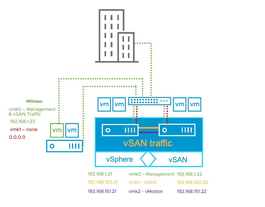
In the below illustration, the 2 Node vSAN Cluster Hosts, Host 1 and Host 2, are both connected to the same Management network as the physical host that is running the vSAN Witness Appliance.

In this configuration, each vSAN Data Node has a dedicated VMkernel interface tagged for "witness" traffic on the 192.168.15.x network. The vSAN Witness Appliance has the WitnessPg (vmk1) VMkernel interface tagged for "vsan" traffic, also on the 192.168.15.x network. In this configuration, static routing is not required because Layer 2 networking is used.
This is a supported configuration.
In the below illustration, the 2 Node vSAN Cluster Hosts, Host 1 and Host 2, are both connected to the same Management network as the physical host that is running the vSAN Witness Appliance.
In this configuration, each vSAN Data Node's Management (vmk0) VMkernel interface is tagged for "witness" traffic on the 192.168.1.x network. The vSAN Witness Appliance has the Management (vmk0) VMkernel interface tagged for "vsan" traffic, also on the 192.168.1.x network. In this configuration, static routing is not required because Layer 2 networking is in use.
This is a supported configuration.
vSAN Witness Appliance Sizing
vSAN Witness Appliance Size
The vSAN witness appliance OVFs are also used for shared witness. When using a vSAN Witness Appliance, the size is dependent on the configurations and this is decided during the deployment process. vSAN Witness Appliance deployment options are hardcoded upon deployment and there is typically no need to modify these.
Compute Requirements
The vSAN Witness Appliance uses a different number of vCPUs depending on the configuration.
Memory Requirements
Memory requirements are dependent on the number of components.
Storage Requirements
Cache Device Size: Each vSAN Witness Appliance deployment option has a cache device size of 10GB. This is sufficient for each for the maximum of 64,000 components. In a typical vSAN deployment, the cache device must be a Flash/SSD device. Because the vSAN Witness Appliance has virtual disks, the 10GB cache device is configured as a virtual SSD. There is no requirement for this device to reside on a physical flash/SSD device. Traditional spinning drives are sufficient.
Capacity Device Sizing: First consider that a capacity device can support up to 21,000 components. Also, consider that a vSAN 2 Node Cluster can support a maximum of 27,000 components. Each Witness Component is 16MB, as a result, the largest capacity device that can be used for storing Witness Components is approaching 350GB.
vSAN Witness Appliance Deployment Sizes & Requirements Summary
Dedicated witness
• Tiny - Supports up to 10 VMs/750 Witness Components -Typical for 2 Node vSAN deployments
o Compute - 2 vCPUs
o Memory - 8GB vRAM
o ESXi Boot Disk - 12GB Virtual HDD
o Cache Device - 10GB Virtual SSD
o Capacity Device - 15GB Virtual HDD
• Medium - Supports up to 500 VMs/21,000 Witness Components - Alternative for 2 Node vSAN deployments with a significant number of components
o Compute - 2 vCPUs
o Memory - 16GB vRAM
o ESXi Boot Disk - 12GB Virtual HDD
o Cache Device - 10GB Virtual SSD
o Capacity Device - 350GB Virtual HDD
• Large - Supports over 500 VMs/45,000 Witness Components - Unnecessary for 2 Node vSAN deployments.
o Compute: 2 vCPUs
o Memory - 32 GB vRAM
o ESXi Boot Disk - 12GB Virtual HDD
o Cache Device - 10GB Virtual SSD
o Capacity Devices - 3x350GB Virtual HDD
8GB ESXi Boot Disk*, one 10GB SSD, three 350GB HDDs
Supports a maximum of 45,000 witness components
Shared witness OVA file for vSAN 7 Update 1
An extra-large option is introduced to accommodate the shared witness appliance's increased number of components.
1000 components per 2-node cluster.
• Tiny - Supports up to 10 VMs/750 Witness Components
o Compute -1 vCPUs
o Memory - 8GB vRAM
• Medium - Supports up to 500 VMs/21,000 Components
o Up to 21 clusters 2-node clusters
o Compute - 2 vCPUs
o Memory - 16GB vRAM
• Large - Supports over 500 VMs/ 24,000 Components
o Up to 24 clusters 2-node clusters
o Compute: 2 vCPUs
o Memory - 32 GB vRAM
• Extra-large - Supports over 500 VMs/ 64,000 Components
o Up to 64 clusters 2-node clusters
o Compute: 6 vCPUs
o Memory - 32 GB vRAM
vSAN Witness Host Versioning & Updating
vSAN Witness Appliance Version
A vSAN Witness Appliance is provided with each release of vSAN. Upon initial deployment of the vSAN Witness Appliance, it is required to be the same as the version of vSAN. The vSphere host that the vSAN Witness Appliance runs on, is not required to be the same version.
Example 1: A new vSAN 6.6.1 deployment
- Requires vSphere 6.5 Update 1 hosts
- Requires vSAN 6.6.1 based vSAN Witness Appliance
- Underlying host can be vSphere 5.5 or higher
Example 2: A new vSAN 6.7 deployment
- Requires vSphere 6.7 hosts
- Requires vSAN 6.7 based vSAN Witness Appliance
- Underlying host can be vSphere 5.5 or higher, but the CPU must be supported by vSphere 6.7
This is because the vSAN Cluster is vSphere 6.7 based and the vSAN Witness Appliance is running vSphere 6.7.
When upgrading the vSAN Cluster, upgrade the vSAN Witness Appliance in the same fashion as upgrading vSphere . This keeps the versions aligned. Be certain to ensure that the underlying hosts and the vCenter Server version supports the version of vSAN being upgraded to.
Successful Example: Upgrade to vSAN 6.6 from vSAN 6.2
- Upgrade vCenter to 6.5 Update 1 using the VCSA embedded update mechanism
- Upgrade vSAN hosts to vSphere 6.5 Update 1 using VMware Update Manager
- Upgrade vSAN Witness Host using VMware Update Manager.
Unsuccessful Example 1: Upgrade to vSAN 6.7 from vSAN 6.6
- Do not upgrade vCenter to 6.7
- Upgrade vSAN hosts to vSphere 6.7 using VMware Update Manager
- Do not upgrade vSAN Witness Host
Unsuccessful Example 2: Upgrade to vSAN 6.7 from vSAN 6.6
- Upgrade vCenter to 6.7 using the VCSA embedded update mechanism
- Upgrade vSAN hosts to vSphere 6.7 using VMware Update Manager
- Do not upgrade vSAN Witness Host
Unsuccessful Example 3: Upgrade to vSAN 6.7 from vSAN 6.6
- Upgrade vCenter to 6.7 using the VCSA embedded update mechanism
- Upgrade vSAN hosts to vSphere 6.7 using VMware Update Manager
- Attempt to upgrade a vSAN Witness Host that is running a vSphere 5.5-6.5 host with CPUs that are not supported by vSphere 6.7
Cluster Settings
Cluster Settings – vSphere HA
Certain vSphere HA behaviors have been modified especially for vSAN. It checks the state of the virtual machines on a per virtual machine basis. vSphere HA can make a decision on whether a virtual machine should be failed over based on the number of components belonging to a virtual machine that can be accessed from a particular partition.
When vSphere HA is configured on a vSAN 2 Node Cluster, VMware recommends the following:
| vSphere HA | Turn on |
| Host Monitoring | Enabled |
| Host Hardware Monitoring – VM Component Protection: “Protect against Storage Connectivity Loss” | Deactivated (default) |
| Virtual Machine Monitoring | Customer Preference – Deactivated by default |
| Admission Control | Set to 50% |
| Host Isolation Response | Deactivated |
| Datastore Heartbeats | “Use datastores only from the specified list”, but do not select any datastores from the list. This Deactivates Datastore Heartbeats |
Note that a 2-node Direct Connect configuration is a special case. In this situation, it is impossible to configure a valid external isolation address within the vSAN network. VMware recommends disabling the isolation response for a 2-node Direct Connect configuration. If however, a host becomes isolated, vSAN has the ability to halt VMs which are "ghosted" (no access to any of the components). This will allow for vSphere HA to safely restart the impacted VMs, without the need to use the Isolation Response.
Using vSphere HA and performing Maintenance
When attempting to perform maintenance on a 2-node vSAN Cluster and vSphere HA is enabled, hosts will not go into maintenance mode automatically. This is because putting one of the 2 hosts into maintenance mode will violate the vSphere HA requirement of having a full host available in the event of a failure.
The correct method to perform maintenance in this situation is to either 1) put the host to be worked on in maintenance mode manually or 2) deactivate vShphere HA during the maintenance operation. This is addressed in KB Article 53682. This is not a vSAN centric issue but affects all 2 host vSphere cluster configurations.
Turn on vSphere HA
To turn on vSphere HA, select the cluster object in the vCenter inventory, Configure, then "Edit "vSphere HA. From here, vSphere HA can be turned on and off via a toggle.

Admission Control
Admission control ensures that HA has sufficient resources available to restart virtual machines after a failure. As a full site failure is one scenario that needs to be taken into account in a resilient architecture, VMware recommends enabling vSphere HA Admission Control. Availability of workloads is the primary driver for most stretched cluster environments. Sufficient capacity must therefore be available for a host failure. Since virtual machines could be equally divided across both hosts in a vSAN 2 Node Cluster, and to ensure that all workloads can be restarted by vSphere HA, VMware recommends configuring the admission control policy to 50 percent for both memory and CPU.
VMware recommends using the percentage-based policy as it offers the most flexibility and reduces operational overhead. For more details about admission control policies and the associated algorithms, we would like to refer to the vSphere 7.0 Availability Guide.
The following screenshot shows a vSphere HA cluster configured with admission control enabled using the percentage-based admission control policy set to 50%.

When you reserve capacity for your vSphere HA cluster with an admission control policy, this setting must be coordinated with the corresponding Primary level of failures to tolerate policy setting in the vSAN rule set. It must not be lower than the capacity reserved by the vSphere HA admission control setting. For example, if the vSAN ruleset allows for only two failures, the vSphere HA admission control policy must reserve capacity that is equivalent to only one or two host failures.
Host Hardware Monitoring – VM Component Protection
vSphere 6.0 introduced a new enhancement to vSphere HA called VM Component Protection (VMCP) to allow for an automated fail-over of virtual machines residing on a datastore that has either an “All Paths Down” (APD) or a “Permanent Device Loss” (PDL) condition.
A PDL, permanent device loss condition, is a condition that is communicated by the storage controller to ESXi host via a SCSI sense code. This condition indicates that a disk device has become unavailable and is likely permanently unavailable. When it is not possible for the storage controller to communicate back the status to the ESXi host, then the condition is treated as an “All Paths Down” (APD) condition.
In traditional datastores, APD/PDL on a datastore affects all the virtual machines using that datastore. However, for vSAN this may not be the case. An APD/PDL may only affect one or few VMs, but not all VMs on the vSAN datastore. Also in the event of an APD/PDL occurring on a subset of hosts, there is no guarantee that the remaining hosts will have access to all the virtual machine objects, and be able to restart the virtual machine. Therefore, a partition may result in such a way that the virtual machine is not accessible on any partition.
Note that the VM Component Protection (VMCP) way of handling a failover is to terminate the running virtual machine and restart it elsewhere in the cluster. VMCP/HA cannot determine the cluster-wide accessibility of a virtual machine on vSAN, and thus cannot guarantee that the virtual machine will be able to restart elsewhere after termination. For example, there may be resources available to restart the virtual machine, but accessibility to the virtual machine by the remaining hosts in the cluster is not known to HA. For traditional datastores, this is not a problem, since we know host-datastore accessibility for the entire cluster, and by using that, we can determine if a virtual machine can be restarted on a host or not.
At the moment, it is not possible for vSphere HA to understand the complete inaccessibility vs. partial inaccessibility on a per virtual machine basis on vSAN; hence the lack of VMCP support by HA for vSAN.
VMware recommends leaving VM Component Protection (VMCP) deactivated.
Datastore for Heartbeating
Virtual Machine Response for Host Isolation
This setting determines what happens to the virtual machines on an isolated host, i.e. a host that can no longer communicate to other nodes in the cluster, nor is able to reach the isolation response IP address.
If we do not have a direct connection between both data nodes in the 2-node cluster - VMware recommends that the Response for Host Isolation is to Power off and restart VMs.
The reason for this is that a clean shutdown will not be possible as on an isolated host the access to the vSAN Datastore, and as such the ability to write to disk, is lost.

Note: A 2-node direct connect configuration is a special case. In this situation, it is impossible to configure a valid external isolation address within the vSAN network. VMware recommends disabling the isolation response for a 2-node direct connect configuration. If however, a host becomes isolated, vSAN has the ability to halt VMs which are "ghosted" (no access to any of the components). This will allow for vSphere HA to safely restart the impacted VMs, without the need to use the Isolation Response.
Advanced Options
When vSphere HA is enabled on a vSAN Cluster, uses heartbeat mechanisms to validate the state of an ESXi host. Network heart beating is the primary mechanism for HA to validate availability of the hosts.
If a host is not receiving any heartbeats, it uses a fail-safe mechanism to detect if it is merely isolated from its HA primary node or completely isolated from the network. It does this by pinging the default gateway.
In vSAN environments, vSphere HA uses the vSAN traffic network for communication. This is different from traditional vSphere environments where the management network is used for vSphere HA communication. However, even in vSAN environments, vSphere HA continues to use the default gateway on the management network for isolation detection responses. This should be changed so that the isolation response IP address is on the vSAN network, as this allows HA to react to a vSAN network failure.
In addition to selecting an isolation response address on the vSAN network, additional isolation addresses can be specified manually to enhance the reliability of isolation validation.
Note: When using vSAN 2 Node clusters in the same location, there is no need to have a separate das.isolationaddress for each of the hosts.
Cluster Settings - DRS
vSphere DRS is used in many environments to distribute load within a cluster. vSphere DRS offers many other features which can be very helpful in stretched environments.
If administrators wish to enable DRS on vSAN 2 Node Cluster, there is a requirement to have a vSphere Enterprise edition or higher.
With vSphere DRS enabled on the cluster, the virtual machines can simply be deployed to the cluster, and then the virtual machine is powered on, DRS will move the virtual machines to either host based on utilization.
In 2 Node vSAN Cluster configurations, vSphere DRS is supported in either Partially Automated or Fully Automated Mode.
Partially Automated Mode: Partially Automated Mode is generally the recommended mode for vSAN Stretched Clusters. This setting does not move workloads back until an Administrator chooses to. By not moving workloads back to a recently unavailable site that has returned, administrators can ensure that resyncs have completed and there isn't any unnecessary traffic across the inter-site link.

For 2 Node configurations that are in different sites, similar to a Stretched Cluster configuration, this is also the general recommendation.
For the more commonly deployed configuration, where nodes are in the same location, Partially Automated Mode or Fully Automated Mode are generally acceptable.
Fully Automated Mode: Fully Automated Mode is not uncommon in 2 Node vSAN cluster configurations when both hosts are at the same physical location.
Unlike Partially Automated Mode, Fully Automated Mode takes over the responsibility of balancing workloads on one host or the other.

In Hybrid 2 Node vSAN Clusters, It is also important to consider Site Read Locality. Like Stretched Clusters, Site Read Locality ensures that reads occur on the site that the virtual machine is running on. This reduces the amount of traffic across a Stretched Cluster's inter-site link.
In 2 Node vSAN cluster configurations that are deployed in a single site, read operations traversing the vSAN network (either directly connected or through a switch) are typically not significant, and Site Read Locality may not provide as significant of a benefit and could be less than desirable. Hybrid 2 Node vSAN Clusters must warm the read cache on a target node when using vMotion or DRS automation. In this scenario it is advantageous to deactivate Site Read Locality to maintain consistent performance when migrating workloads from one Hybrid node to another.
Site Read Locality for releases previous to vSAN 6.7 Update 1 can be deactivated by changing the /VSAN/DOMOwnerForceWarmCache value to 1.
vSAN 6.7 Update 1 and higher releases can use the Site Read Locality option in the vSAN Configuration UI> 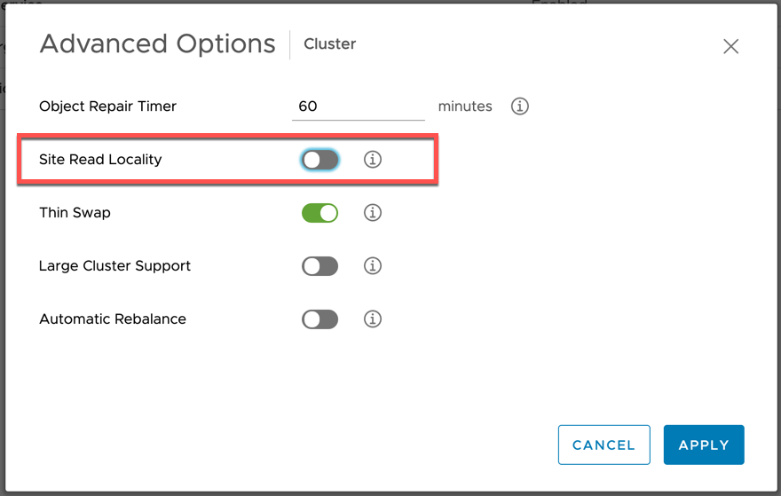
Using a vSAN Witness Appliance
VMware vSAN 2 Node Clusters supports the use of a vSAN Witness Appliance as the vSAN Witness host. This is available as an OVA (Open Virtual Appliance) from VMware. However this vSAN Witness Appliance needs to reside on a physical ESXi host, which requires some special networking configuration.
Setup Step 1: Deploy the vSAN Witness Appliance
The vSAN Witness Appliance must be deployed on different infrastructure than the 2 Node vSAN Cluster itself. This step will cover deploying the vSAN Witness Appliance to a different cluster.
Note: It is considered supported for a dedicated server located in the same chassis as is the case in a HPE Synergy frame, or a Dell XR4000.
The first step is to download and deploy the vSAN Witness Appliance, or deploy it directly via a URL, as shown below. In this example it has been downloaded:

Select a Datacenter for the vSAN Witness Appliance to be deployed to and provide a name (Witness1 or something similar).

Select a cluster for the vSAN Witness Appliance to reside on.

Review the details of the deployment and press next to proceed.

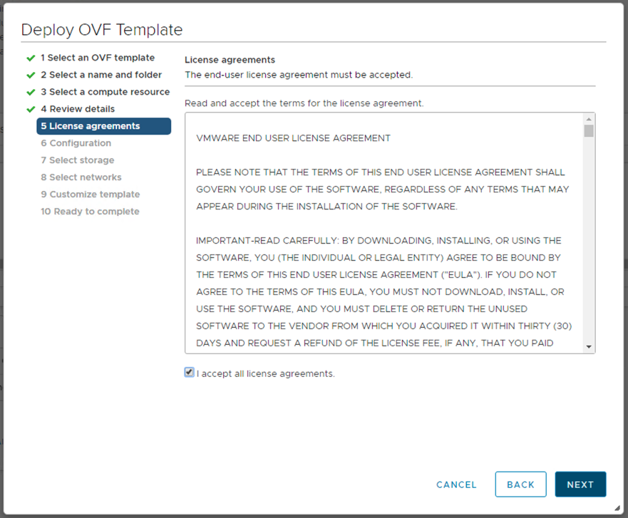
The license must be accepted to proceed.
At this point a decision needs to be made regarding the expected size of the 2 Node vSAN Cluster configuration. There are three options offered. If you expect the number of VMs deployed on the vSAN 2 Node Cluster to be 10 or fewer, select the Tiny configuration. If you expect to deploy more than 10 VMs, but less than 500 VMs, then the Normal (default option) should be chosen. On selecting a particular configuration, the resources consumed by the appliance and displayed in the wizard (CPU, Memory and Disk):

Select a datastore for the vSAN Witness Appliance. This will be one of the datastore available to the underlying physical host. You should consider when the vSAN Witness Appliance is deployed as thick or thin, as thin VMs may grow over time, so ensure there is enough capacity on the selected datastore.

Select a network for the Management Network and for the Witness (or Secondary) Network.

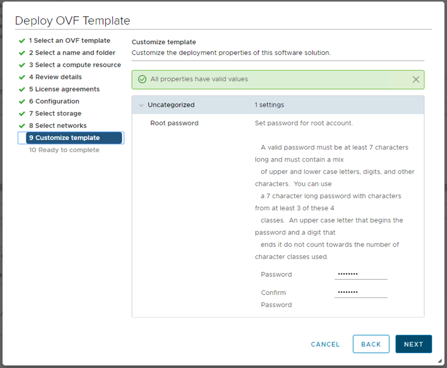
Give a root password for the vSAN Witness Appliance:
At this point, the vSAN Witness Appliance is ready to be deployed. It will need to be powered on manually via the vSphere web client UI later:

Once the vSAN Witness Appliance is deployed and powered on, select it in the vSphere web client UI and begin the next steps in the configuration process.
Setup Step 2: vSAN Witness Appliance Management
Once the vSAN Witness Appliance has been deployed, select it in the vSphere web client UI, open the console.
The console of the vSAN Witness Appliance should be access to add the correct networking information, such as IP address and DNS, for the management network.
On launching the console, unless you have a DHCP server on the management network, it is very likely that the landing page of the DCUI will look something similar to the following:

Use the <F2> key to customize the system. The root login and password will need to be provided at this point. This is the root password that was added during the OVA deployment earlier.
Select the Network Adapters view. There will be two network adapters, each corresponding to the network adapters on the virtual machine. You should note that the MAC address of the network adapters from the DCUI view match the MAC address of the network adapters from the virtual machine view. Because these match, there is no need to use promiscuous mode on the network, as discussed earlier.
Select vmnic0, and if you wish to view further information, select the key <D> to see more details.

Navigate to the IPv4 Configuration section. This will be using DHCP by default. Select the static option as shown below and add the appropriate IP address, subnet mask and default gateway for this vSAN Witness Appliance Management Network.

The next step is to configure DNS. A primary DNS server should be added and an optional alternate DNS server can also be added. The FQDN, fully qualified domain name, of the host should also be added at this point.

One final recommendation is to do a test of the management network. One can also try adding the IP address of the vCenter server at this point just to make sure that it is also reachable.

When all the tests have passed, and the FQDN is resolvable, administrators can move onto the next step of the configuration, which is adding the vSAN Witness Appliance ESXi instance to the vCenter server
Setup Step 3: Add Witness to vCenter Server
There is no difference to adding the vSAN Witness Appliance ESXi instance to vCenter server when compared to adding physical ESXi hosts. However, there are some interesting items to highlight during the process. First step is to provide the name of the Witness. In this example, vCenter server is managing multiple data centers, so we are adding the host to the witness data center.

Provide the appropriate credentials. In this example, the root user and password.

Acknowledge the certificate warning:

There should be no virtual machines on the vSAN Witness Appliance. Note: It can never run VMs in a vSAN 2 Node Cluster configuration. Note also the mode: VMware Virtual Platform. Note also that builds number may differ to the one shown here.

The vSAN Witness Appliance also comes with its own license. You do not need to consume vSphere licenses for the witness appliance:

Lockdown mode is deactivated by default. Depending on the policies in use at a customer’s site, the administrator may choose a different mode to the default:

Click Finish when ready to complete the addition of the Witness to the vCenter server:

One final item of note is the appearance of the vSAN Witness Appliance ESXi instance in the vCenter inventory. It has a light blue shading, to differentiate it from standard ESXi hosts. It might be a little difficult to see in the screen shot below, but should be clearly visible in your infrastructure. (Note: In vSAN 6.1 and 6. 2 deployments, the “No datastores have been configured” message is because the nested ESXi host has no VMFS datastore. This can be ignored.)

One final recommendation is to verify that the settings of the vSAN Witness Appliance matches the Tiny, Normal or Large configuration selected during deployment. For example, the Normal deployment should have an 12GB HDD for boot in vSAN 6.5 (8GB for vSAN 6.1/6.2), a 10GB Flash that will be configured later on as a cache device and another 350 HDD that will also be configured later on as a capacity device.

Once confirmed, you can proceed to the next step of configuring the vSAN network for the vSAN Witness Appliance
Setup Step 4: Config vSAN Witness Host Networking
The next step is to configure the vSAN network correctly on the vSAN Witness Appliance. When the Witness is selected, navigate to Configure > Networking > Virtual switches as shown below.

The Witness has a portgroup pre-defined called witnessPg. Here the VMkernel port to be used for vSAN traffic is visible. If there is no DHCP server on the vSAN network (which is likely), then the VMkernel adapter will not have a valid IP address. Select VMkernel adapters > vmk1 to view the properties of the witnessPg. Validate that "vSAN" is an enabled service as depicted below.

* Engineering note: A few things to consider when configuring vSAN traffic on the vSAN Witness Appliance.
- The default configuration has vmk0 configured for Management Traffic and vmk1 configured for vSAN Traffic.
- The vmk1 interface cannot be configured with an IP address on the same range as that of vmk0. This is because Management traffic and vSAN traffic use the default TCP/IP stack. If both vmk0 and vmk1 are configured on the same range, a multihoming condition will occur and vSAN traffic will flow from vmk0, rather than vmk1. Health Check reporting will fail because vmk0 does not have vSAN enabled. The multihoming issue is detailed in KB 2010877 ( https://kb.vmware.com/kb/2010877 ).
- In the case of 2 Node vSAN, If it is desired to have vSAN traffic on the same subnet as vmk0, (or simply use a single interface for simplicity), it is recommended todeactivate vSAN services on vmk1 (WitnessPg) and enable vSAN services on vmk0 (Management). This is a perfectly valid and supported configuration.
Configure the network address
Select the witnessPg and edit the properties by selecting the pencil icon.

If vSAN is not an enabled service, select the witnessPg portgroup, and then select the option to edit it. Tag the VMkernel port for vSAN traffic, as shown below:

Next, ensure the MTU is set to the same value as the vSAN Data Node hosts’ vSAN VMkernel interface. *

In the IPV4 settings, a default IP address has been allocated. Modify it for the vSAN traffic network.

Once the witnessPg VMkernel interface address has been configured, click OK.
Static routes are still required by the witnessPg VMkernel interface (vmk1) as in vSAN 6.1 or 6.2. The "Override default gateway for this adapter" setting is not supported for the witness VMkernel interface (vmk1). Static routing is covered in detail in the Validate Networking section
* Note - Mixed MTU for witness traffic separation introduced in vSAN 6.7 Update 1. vSAN now supports different MTU settings for the witness traffic VMkernel interface and the vSAN data network VMkernel interface. This capability provides increased network flexibility for stretched clusters and 2-node clusters that utilize witness traffic separation.
Networking & Promiscuous mode
The vSAN Witness Appliance contains two network adapters that are connected to separate vSphere Standard Switches (VSS).
The vSAN Witness Appliance Management VMkernel is attached to one VSS, and the WitnessPG is attached to the other VSS. The Management VMkernel (vmk0) is used to communicate with the vCenter Server for appliance management. The WitnessPG VMkernel interface (vmk1) is used to communicate with the vSAN Network. This is the recommended configuration. These network adapters can be connected to different, or the same, networks. As long as they are fully routable to each other, it’s supported, separate subnets or otherwise.
The Management VMkernel interface could be tagged to include vSAN Network traffic as well as Management traffic. In this case, vmk0 would require connectivity to both vCenter Server and the vSAN Network.
In many nested ESXi environments, there is a recommendation to enable promiscuous mode to allow all Ethernet frames to pass to all VMs that are attached to the port group, even if it is not intended for that particular VM. The reason promiscuous mode is enabled in many nested environments is to prevent a virtual switch from dropping packets for (nested) vmnics that it does not know about on nested ESXi hosts.
A Note About Promiscuous Mode
In many nested ESXi environments, there is a recommendation to enable promiscuous mode to allow all Ethernet frames to pass to all VMs that are attached to the port group, even if it is not intended for that particular VM. The reason promiscuous mode is enabled in these environments is to prevent a virtual switch from dropping packets for (nested) vmnics that it does not know about on nested ESXi hosts. Nested ESXi deployments are not supported by VMware other than the vSAN Witness Appliance.
The vSAN Witness Appliance is essentially a nested ESXi installation tailored for use with vSAN Stretched Clusters.
The MAC addresses of the VMkernel interfaces vmk0 & vmk1 are configured to match the MAC addresses of the vSAN Witness Appliance host's NICs, vmnic0 and vmnic1. Because of this, packets destined for either the Management VMkernel interface (vmk0) or the WitnessPG VMkernel interface, are not dropped.

Because of this, promiscuous mode is not required when using a vSAN Witness Appliance
Configuring 2 Node vSAN
Pre-Requisites
To properly configure 2 Node vSAN, it is important to have a few pre-requisites in place.
- Determine whether Witness Traffic Separation will be used or not.
- Determine whether the vSAN Witness Host will be a vSAN Witness Appliance or a Physical vSphere Host
- Determine where the vSAN Witness Appliance will be hosted (if used)
- Determine where the vSAN Witness Appliance will be hosted (if used)
- Ensure connectivity between the 2 Node cluster and the vSAN Witness Host
- If using Witness Traffic Separation - A VMkernel interface other than the vSAN Network will be required
- If not using Witness Traffic Separation - The vSAN Network will be required to have connectivity to the vSAN Witness Host
- Configure appropriate networking
- For vCenter
- vCenter must be able to communicate with the Management interface on each vSAN Host
- vCenter must be able to communicate with the Management interface for the vSAN Witness Host
- For vSAN Hosts
- The vSAN Host Management interface must be able to communicate with vCenter
- vSAN Hosts must be able to communicate with each other
- vSAN Hosts must be able to communicate with the vSAN Witness Host vSAN Tagged interface
- For vSAN Witness Host
- The vSAN Witness Host Management interface must be able to communicate with vCenter
- The vSAN Witness Host vSAN Tagged interface must be able to communicate with the vSAN Nodes
- For vCenter
VMkernel Interfaces
VMkernel interfaces provide connectivity for different inter-node communication between vSpehre hosts. IP-based storage protocols typically have dedicated VMkernel interfaces on isolated networks. It is considered a best practice and VMware recommendation to isolate storage traffic. vSAN may only use VMkernel interfaces that are appropriate tagged for vSAN traffic types.
In most vSAN configurations, each vSAN tagged VMkernel interface must be able to commuicate with each and every other vSAN tagged VMkernel interface. This is true for normal vSAN clusters as well as 2 Node vSAN Clusters up to version 6.2 using vSphere 6.0 Update 2.
Witness Traffic Separation was publicly introduced with vSAN 6.5, but is also included in vSAN 6.2 as of vSphere 6.0 Update 3 (vCenter and vSphere versions). Witness Traffic Separation removes the requirement for traffic to and from the vSAN Witness Host to be available from the vSAN data network. A "front-end facing" VMkernel interface may be used, allowing the "back-end" of 2 Node vSAN to use VMkernel ports that are directly connected across hosts. The back-end vSAN network can still be connected to a switch if desired.
Using Witness Traffic Separation is the preferred method for configuring 2 Node vSAN as of vSphere 6.0 Update 3, wether using direct connect or using a switch for the back-end vSAN data network. Because of this, the previously required method will not be addressed.
Configuring the back-end VMkernel ports may be accomplished using Configuration Assist, but the Witness Traffic Separation ports must still be configured manually.
It is also recommended to configure 2 Node vSAN networking before configuring the 2 Node vSAN cluster.
VMkernel Interfaces - Witness Traffic
Using Witness Traffic Separation for vSAN Witness Traffic
Since the public introduction of Witness Traffic Separation in vSphere 6.5, this has become the preferred method of allowing communication with the vSAN Witness Host.
As previously discussed, Witness Traffic Separation separates the networking requirements for vSAN data and vSAN metadata communication to the vSAN Witness Host. Communication to the vSAN Witness Host is performed through a different VMkernel interface than the interface used to communicate between vSAN Data nodes.
Data nodes can use a direct connection between nodes or may be connected to a traditional switch, which could be part of an isolated data network.
Communication with the vSAN Witness Host is configured separately from the back-end vSAN Data network.
Creating the vSAN Witness Traffic VMkernel interfaces can be accomplished in the following fashion:
- Create a new VMkernel port for use as a Witness Traffic interface

- This will typically be on the same virtual switch as the Management interface (vSwitch0)
- Give the VMkernel interface a descriptive label and be certain to select the appropriate VLAN if necessary.
Do not enable any services on the VMkernel interface.
- Enter the appropriate network settings
*Note: the Default gateway may not be set. vSAN uses the same TCP/IP stack as the Management interface and may not use an alternate gateway. It is important to also ensure that this VMkernel interface is NOT on the same TCP/IP network as the Management interface.
- Select Finish to complete creating the VMkernel interface.
- Reviewing the VMkernel adapters, the newly created VMkernel interface does not have the proper tagging in place.
- In the HTML5 client (vSphere 6.7):
- From the ESXi console:
- In the HTML5 client (vSphere 6.7):
- To enable this vSAN Witness traffic on the VMkernel interface in the illustration (vmk1) there are a couple methods that can be used to enable vSAN Witness Traffic.
- Enable SSH on the vSAN Host and run the following command:
esxcli vsan network ip add -i <VMkernel for Witness Traffic> -T=witness

example: esxcli vsan network ip add -i vmk1 -T=witness
- Use the vSphere CLI to connect to the vSAN Host and run the following command:
esxcli vsan network ip add -i <VMkernel for Witness Traffic> -T=witness

example: esxcli vsan network ip add -i vmk1 -T=witness
- Run the following single line PowerCLI script against the vSAN Host:
Connect-VIServer <vSAN Host>; $EsxCli = Get-EsxCli  -V2 ; $VMkArgs = $EsxCli.vsan.network.ip.add.CreateArgs() ; $VMkArgs.interfacename = <VMkernel for Witness Traffic> ; $VMkArgs.traffictype = "witness" ; $EsxCli.vsan.network.ip.add.Invoke($VMkArgs) ; Disconnect-VIServer -Confirm:$false

example: Connect-VIServer "host1.demo.local"; $EsxCli = Get-EsxCli -V2; $VMkArgs = $EsxCli.vsan.network.ip.add.CreateArgs(); $VMkArgs.interfacename = "vmk1"; $VMkArgs.traffictype = "witness" ; $EsxCli.vsan.network.ip.add.Invoke($VMkArgs); Disconnect-VIServer -Confirm:$false
- Enable SSH on the vSAN Host and run the following command:
- Reviewing the VMkernel adapters again, the newly tagged VMkernel interface does have the proper tagging in place.
- In the HTML5 client (vSphere 6.7):
- From the ESXi console:
- In the HTML5 client (vSphere 6.7):
- The "Witness Tagged" VMkernel interface will need to have connectivity to the "vSAN Traffic" tagged interface on the vSAN Witness Host. In cases where this connectivity is over Layer 3, static routes must be added. This is because vSAN uses the default TCP/IP stack and will attempt to use the Management VMkernel's default gateway.
To add a static route on the vSAN data nodes to the vSAN Witness Host's "vSAN Tagged" VMkernel interface, perform one of the following methods:
- Enable SSH on the vSAN Host, login, and run the following command:
esxcfg-route -a <target address/prefixlength> <gateway to use>

example: esxcfg-route -a "192.168.110.0/24 192.168.15.1"
- Use the vSphere CLI to connect to the vSAN Host and run the following command:
esxcfg-route -a <target address/prefixlength> <gateway to use>

example: esxcfg-route -a "192.168.110.0/24 192.168.15.1"
- Run the following single line PowerCLI script against the vSAN Host:
Connect-VIServer <vSAN Host>; New-VMHostRoute -Destination <target address> -PrefixLength <prefixlength> -Gateway <gateway to use> -Confirm:$false; Disconnect-VIServer -Confirm:$false

example: Connect-VIServer "host1.demo.local"; New-VMHostRoute -Destination "192.168.110.0" -PrefixLength "24" -Gateway "192.168.15.1" -Confirm:$false; Disconnect-VIServer -Confirm:$false
- Enable SSH on the vSAN Host, login, and run the following command:
- Confirm the Witness Tagged VMkernel interface can ping the vSAN Witness Host vSAN Traffic tagged VMkernel interface:
- Enable SSH on the vSAN Host, login, and run the following command:
vmkping -I <host Witness Tagged VMkernel interface name> <vSAN Witness Host vSAN Tagged interface IP address>

example: vmkping -I vmk1 192.168.110.23
- Run the following single line PowerCLI script against the vSAN Host:
Connect-VIServer <vSAN Host> -user root; EsxCli = Get-EsxCli -V2; $VMkArgs = $EsxCli.network.diag.ping.CreateArgs(); $VMkArgs.interface = <Witness Tagged interface name>; $VMkArgs.host = <vSAN Witness Host vSAN Tagged interface IP address>; $EsxCli.network.diag.ping.Invoke($VMkArgs).Summary; Disconnect-VIServer -Confirm:$false

example: Connect-VIServer "host1.demo.local" -user root; EsxCli = Get-EsxCli -V2; $VMkArgs = $EsxCli.network.diag.ping.CreateArgs(); $VMkArgs.interface = "vmk1"; $VMkArgs.host = "192.168.110.23"; $EsxCli.network.diag.ping.Invoke($VMkArgs).Summary; Disconnect-VIServer -Confirm:$false
- Enable SSH on the vSAN Host, login, and run the following command:
.png)
.png)
.png)
.png)
.png)
.png)


Once Witness Traffic Separation networking has been configured on the first host, repeat the process for the second host.
*Important things to consider/remember:
- The VMkernel interface for Witness Traffic may not be on the same network as the Management interface (vmk0). If Witness Traffic must be run on the same network as vmk0, simply skip steps 1-6 and tag vmk0 in step 7 instead.
- Witness Traffic from data nodes to the vSAN Witness Host contain no virtual machine data, but rather vSAN metadata, such as vSAN component placement, vSAN node ownership, etc. Tagging vmk0 for Witness Traffic is fully supported.
VMkernel Interfaces - vSAN Traffic - VSS
The back-end vSAN Data network is configured in the same fashion for 2 Node vSAN as any other vSAN network.
vSAN back-end networking may use either a vSphere Standard Switch or vSphere Distributed Switch. This document will only focus on the setup process and not the feature set differences between each of these.
Using a vSphere Standard Switch
Creating the vSAN Traffic VMkernel interfaces can be accomplished in the following fashion:
- Create a new VMkernel port for use as a vSAN Traffic interface on the first host.
- This will typically be on a different virtual switch from the Management interface (vSwitch0).
- When creating a new vSphere Standard Switch, adapters will have to be assigned. Click the plus to assign adapters to this vSphere Standard Switch.
- Select one or more adapters that will be used for vSAN Traffic and select OK.
- When all adapters have been added, select Next.
- Give the VMkernel interface a descriptive label and be certain to select the appropriate VLAN if necessary.
Enable vSAN services on the VMkernel interface.
- Enter the appropriate network settings
*Note: the Default gateway may not be set. vSAN uses the same TCP/IP stack as the Management interface and may not use an alternate gateway. It is important to also ensure that this VMkernel interface is NOT on the same TCP/IP network as the Management interface.
- Select Finish to complete creating the VMkernel interface.
- Reviewing the VMkernel adapters, the newly created VMkernel interface does not have the proper tagging in place.
- In the HTML5 client (vSphere 6.7):
- From the ESXi console:
Notice vmk2 has vSAN Traffic Tagged and vmk1 has Witness Traffic Tagged.
- In the HTML5 client (vSphere 6.7):
- Repeat this process for the second host.
.png)
.png)
.png)

.png)
.png)
.png)
.png)


VMkernel Interfaces - vSAN Traffic - VDS
Using a vSphere Distributed Switch
Creating the vSAN Witness Traffic VMkernel interfaces can be accomplished in the following fashion:
- Create a new VMkernel port for use as a vSAN Traffic interface on the first host.
- When using a vSphere Distributed Switch, select an existing network that has been previously created.
- Select browse and choose the vSAN Port Group on the VDS and select OK.
- Select Next.
- Select the appropriate VLAN if necessary and check vSAN in the Available services. This is "tagging" this VMkernel interface for vSAN Traffic.
- Enter the appropriate network settings
*Note: the Default gateway may not be set. vSAN uses the same TCP/IP stack as the Management interface and may not use an alternate gateway. It is important to also ensure that this VMkernel interface is NOT on the same TCP/IP network as the Management interface.
- Select Finish to complete creating the VMkernel interface.
- Reviewing the VMkernel adapters, the newly created VMkernel interface does not have the proper tagging in place.
- In the HTML5 client (vSphere 6.7):
- From the ESXi console:
Notice vmk2 has vSAN Traffic Tagged and vmk1 has Witness Traffic Tagged.
- In the HTML5 client (vSphere 6.7):
- Repeat this process for the vMotion Network.
- Repeat this process for the vSAN and vMotion Network for the second host.


 *Note: the Default gateway may not be set. vSAN uses the same TCP/IP stack as the Management interface and may not use an alternate gateway. It is important to also ensure that this VMkernel interface is NOT on the same TCP/IP network as the Management interface.

 Notice vmk2 has vSAN Traffic Tagged and vmk1 has Witness Traffic Tagged.
Creating a New 2 Node vSAN Cluster
Creating the vSAN Cluster
The following steps should be followed to install a new 2 Node vSAN Cluster.
In this example, there are 2 nodes available: host1.demo.local and host2.demo.local. Both hosts reside in a vSphere cluster called 2 Node. vSAN Witness Host, witness.demo.central. is in its own data center and is not added to the cluster.
To setup 2 Node vSAN, Configure > vSAN > Services . Click Configure to begin the vSAN wizard.

Create Step 1 Configure vSAN as a 2 Node vSAN Cluster
The initial wizard allows for choosing various options like enabling Deduplication and Compression (All-Flash architectures only with Advanced or greater licensing) or Encryption (Enterprise licensing required) for vSAN. Select Two host vSAN Cluster and Next.

Create Step 2 Configure Services
Select the services desired that are compatible with the hardware and licensing options for the cluster.

- Deduplication and Compression will require vSAN Advanced licensing or higher and All-Flash hardware
- Encryption will require vSAN Enterprise Licensing and an available KMIP 1.1 compliant Key Management Server (KMS).
In a vSAN 2 Node, it is important to get into the habit of using Allow Reduced Redundancy. This is because any time there is a requirement to create/remove/recreate a vSAN Disk Group on a 2 Node vSAN Cluster, the Allow Reduced Redundancy option is required. Without this setting checked, changes will likely not occur due to the cluster not being able to maintain storage policy compliance.
Create Step 3 Claim Disks
Disks should be selected for their appropriate role in the vSAN cluster.
 Click Next.
Create Step 4 Create Fault Domains
The Create fault domain wizard will allow hosts to be selected for either the Preferred or Secondary fault domain. The default naming of these two fault domains is Preferred and Secondary.

Select one host and choose >> to move it to the Secondary fault domain.
Click Next .
Create Step 5 Select Witness Host
The vSAN Witness host detailed earlier must be selected to act as the vSAN Witness for the 2 Node vSAN Cluster.

Click Next .
Create Step 6 Claim Disks for Witness Host
Just like physical vSAN hosts, the vSAN Witness needs a cache tier and a capacity tier. * Note: The vSAN Witness does not actually require SSD backing and may reside on a traditional mechanical drive.

Be certain to select the 10GB device as the cache device and the 15GB device as a capacity device.
Select Next .
Create Step 7 Complete
Review the vSAN 2 Node Cluster configuration for accuracy and click Finish.

Upgrading a older 2 Node vSAN Cluster
Upgrading a vSAN 2 Node Cluster is very easy. It is important though to follow a sequence of steps to ensure the upgrade goes smoothly.
Upgrading Step 1: Upgrade vCenter Server
As with any vSphere upgrades, it is typically recommended to upgrade vCenter Server first. While vCenter Server for Windows installations are supported, the steps below describe the process when using the vCenter Server Appliance (VCSA).
Log in to the VAM I interface and select Update from the Navigator pane to begin the upgrade process.

*Refer to the documentation for vCenter Server for Windows to properly upgrade to a newer release of vCenter Server.
After the upgrade has completed, the VCSA will have to be rebooted for the updates to be applied. It is important to remember that vSAN Health Check will not be available until after hosts have been upgraded.

Upgrading Step 2: Upgrade Each Host
Upgrading each host is the next task to be completed. There are a few considerations to remember when performing these steps.
As with any upgrade, hosts will be required to be put in maintenance mode, remediated, upgraded, and rebooted. Maintenance mode will require the “ensure accessibility” method is selected, and read operations will be performed by the alternate host. In Hybrid configurations it may be advantageous to enable the /VSAN/DOMOwnerForceWarmCache setting to ensure reads are always distributed across hosts, which will mitigate the warming process required when a virtual machine moves to the alternate host.
With vSphere DRS in place, will ensure that virtual machines are moved to the alternate host. If DRS is set to “fully automated” virtual machines will vMotion to the other host automatically, while “partially automated” or “manual” will require the virtualization admin to vMotion the virtual machines to the other host manually.
Upgrading Step 3: Upgrade the Witness Host
After both vSAN Data Nodes have been upgraded, the vSAN Witness Host will also need to be upgraded. The Health Check will show that the vSAN Witness Host has not been upgraded.

Upgrading the vSAN Witness Host is done in the same way that any other ESXi hosts are updated. It is important to remember that as the vSAN Witness Host is upgraded, the witness components will no longer be available and objects will be non-compliant. Objects will report that the Witness component is not found.

After the upgrade is complete, the Witness component will return and will reside on the vSAN Witness Host.

Upgrading Step 4: Upgrade the on-disk Format if necessary
The final step in the upgrade process will be to upgrade the on-disk format. To use the new features, from time to time the on-disk format must be upgraded to the required version. The Health Check will assume that the vSphere version will prefer a native on-disk format for that version, and as a result, it will throw an error until the format is upgraded.

To upgrade the on-disk format from an older version to a newer version, select Manage > General under vSAN. Then click Upgrade under the On-disk Format Version section.

Depending on the on-disk format version an upgrade will either perform a rolling upgrade across the hosts in the cluster or make a small metadata update. In the event a rolling upgrade is required, each host’s disk groups will be removed and recreated with the new on-disk format. The amount of time required to complete the on-disk upgrade will vary based on the cluster hardware configuration, how much data is on the cluster, and whatever over disk operations are occurring on the cluster. The on-disk rolling upgrade process does not interrupt virtual machine disk access and is performed automatically across the hosts in the cluster.
The witness components residing on the vSAN Witness Host will be deleted and recreated. This process is relatively quick given the size of witness objects.
Converting a 2 Node Cluster with WTS to a 3 Node Cluster
How can a 2 Node Cluster be converted to a 3 Node Cluster when using Witness Traffic Separation (WTS)?
This is a very common question asked by customers who start small with 2 Node vSAN and wish to grow the cluster to 3 or more hosts at a later time.
2 Node vSAN is essentially a 1+1+1 Stretched Cluster configuration, which requires a vSAN Witness Host. Alternatively, "traditional" vSAN Clusters do not require a vSAN Witness Host.
To convert a 2 Node Cluster to a larger cluster with 3 or more hosts, a few steps must be accomplished in a particular order of operations.
Basic Workflow
The process of converting a 2 Node Cluster to a Cluster with 3 or more hosts is as follows:
- Ensure Node to Node connectivity for the vSAN Data Nodes
- Remove the vSAN Witness Host
- Add the 3rd, 4th, 5th, and subsequent Nodes to the Cluster
Some additional workflow considerations
Some additional items to consider when planning to move from a 2 Node vSAN Cluster to a larger "traditional" cluster:
- Are the 2 Nodes connected directly to each other, as in a Direct Connect configuration?
- This is important, because all hosts in a cluster will have to be connected to a switch
- Is Witness Traffic Separation (WTS) being used?
- WTS was publicly introduced in vSAN 6.5, but works with vSAN 6.0 U3 or higher.
- Traditional vSAN clusters do not use WTS
- What version of vSphere/vSAN is being used?
- vSphere 6.0/6.5/6.7, and vSAN 6.1/6.2/6.5/6.6/6.7 respectively, hosts can simply be added to a vSphere cluster
- When using Cluster Quickstart, vSphere 6.7 Update 1 requires hosts to be added to a vSphere cluster using the Cluster Quickstart
Networking - Hosts are directly connected when using WTS
Because vSAN clusters that have more than 2 Nodes must be connected to a switch for vSAN traffic, it is important to migrate the direct connection to a switch.
These steps will ensure the availability of vSAN data and virtual machines when migrating to a switch for vSAN traffic.
- Migrate any virtual machines to the host that is in the Fault Domain that is designated as "Preferred".
- This Fault Domain is often named "Preferred" but could have been given a different name during configuration.
- The asterisk in the Fault Domains UI will indicate which host is "Preferred"
- When all workloads have been migrated to the preferred host, place the other host in Maintenance Mode, choosing Ensure Accessibility
- Disconnect the direct connected uplink(s) from the alternate host (non-preferred) and connect it to an appropriate switch
- This will connect the preferred host to the switch
- Connect the non-preferred node to the switch, just as the preferred node is connected
- Confirm connectivity between the preferred and non-preferred nodes
- On each node, from the ESXi shell, use vmkping to confirm connectivity
- vmkping -I vmX (vSAN tagged VMkernel interface) <IP Address of alternate host vSAN tagged VMkernel>
- vmkping -I vmX (vMotion tagged VMkernel interface) <IP Address of alternate host vMotion tagged VMkernel>
- When connectivity is confirmed, exit maintenance mode on the non-preferred node
Proceed to the next section.
Converting from 2 Node to 3 Node when all data nodes are connected to a switch
When all vSAN Nodes are connected to a switch, and vSAN VMkernel interfaces are properly communicating between nodes, the process to move from 2 Node vSAN to 3 or more nodes is very straightforward.
- Deactivate Stretched Clustering
- If In the Fault Domains UI, select Deactivate
- Remove the vSAN Witness Host
- Remove the Fault Domains because they are not necessary
- Select each Fault Domain from the Fault Domains UI, and Remove
- Select each Fault Domain from the Fault Domains UI, and Remove
- If the hosts are using Witness Traffic Separation (WTS) it is important to untag "witness" traffic
- This can be accomplished using the following command from the ESXi shell/console: esxcli vsan network remove -i vmkX (vmkX is the VMkernel interface that has "witness" traffic tagged)
- Alternatively, using PowerCLI, the following one-liner may be used (must be connected to vCenter first): Get-Cluster -Name CLUSTERNAME | Get-VMHost | Get-EsxCli -v2 | % { $_.vsan.network.remove.Invoke(@{interfacename='vmkX'})}
- If In the Fault Domains UI, select Deactivate
- Configure networking on 3rd host
- Configure the vSAN Network on the 3rd host
- Configure the vMotion Network on the 3rd host
- Configure the vSAN Network on the 3rd host
- Add 3rd host to the vSAN cluster & claim disks
- If using the Cluster Quickstart:
- Use the Cluster Quickstart to add the host to the cluster
- Use the Cluster Quickstart to create the disk group(s)
- Use the Cluster Quickstart to add the host to the cluster
- If not using the Cluster Quickstart
- Hosts are added to the Cluster by
- Right clicking the host and selecting Move to
- Dragging a host into the Cluster
- Right clicking the Cluster and adding a host not previously added to vCenter
- Disk Groups can be added using the Add Disk Group option in Disk Management
- Hosts are added to the Cluster by
- If using the Cluster Quickstart:
- Rebuild the vSAN Witness Components on the 3rd Node
- Because the Witness Components were previously on the vSAN Witness Host, they must be recreated for vSAN Objects to be compliant.
- These will be recreated automatically when the CLOM Repair Timer expires, or an administrator may immediately recreate them through the vSAN Health Check
- Select Monitor from the vSAN Cluster UI
- Select vSAN - Health
- Expand the Data alarm and select "Repair Objects Immediately"


Below is a narrated video that goes through the process for a 2 Node vSAN 6.7 Update 1 cluster:
Summary
The process to convert a 2 Node vSAN Cluster to a 3 (or more) Node vSAN Cluster is relatively easy, but does require a particular step to be taken.
Any vSAN 2 Node cluster can be converted to 3 or more nodes.
There is no architectural or licensing limitation when converting from 2 Node to 3 or more node vSAN provided appropriate licensing is assigned to the cluster.
Management and Maintenance
The following section of the guide covers considerations related to management and maintenance of 2 Node vSAN.
Maintenance Mode Considerations
In any situation where a 2 Node vSAN cluster has an inaccessible host or disk group, vSAN objects are at risk of becoming inaccessible should another failure occur.
Maintenance Mode on the Witness Host
When a host fails, vSAN cannot rebuild data on another host to protect against another failure.
If a host must enter maintenance mode, vSAN cannot evacuate data from the host to maintain policy compliance. While the host is in maintenance mode, data is exposed to a potential failure or inaccessibility should an additional failure occur.
Maintenance Mode on a Data Node
When placing a vSAN host in maintenance mode, the vSAN data migration options are:
o Full data migration – Not available for two-node vSAN clusters using the default storage policy, as policy compliance requires two for data and one for the witness object
o Ensure accessibility – The preferred option for two-host or three-host vSAN clusters using the default storage policy. Ensure accessibility guarantees the enough components of the vSAN object are available for the object to remain available. Though still accessible, vSAN objects on two-host or three-host clusters are no longer policy
compliant. When the host is no longer in maintenance mode, objects will be rebuilt to ensure policy compliance. During this time however, vSAN objects are at risk because they will become inaccessible if another failure occurs.
Any objects that have a non-standard single copy storage policy (FTT=0) will be moved to an available host in the cluster. If there is not sufficient capacity on any alternate hosts in the cluster, the host will not enter maintenance mode.
o No data migration – This is not a recommended option for vSAN clusters. vSAN objects that use the default vSAN Storage Policy may continue to be accessible, but vSAN does not ensure their accessibility.
Any objects that have a non-standard single copy storage policy (FTT=0) will become inaccessible until the host exits maintenance mode.
Maintenance Mode on the vSAN Witness Host
Maintenance mode on the vSAN Witness Host is typically an infrequent event. Different considerations should be taken into account, depending on the type of vSAN Witness Host used:
o vSAN Witness Appliance (recommended) – No virtual machine workloads may run here. The only purpose of this appliance is to provide quorum for the 2 Node vSAN Cluster. Maintenance mode should be brief, typically associated with updates and patching.
o Physical ESXi Host – While not typical, a physical host may be used as a vSAN Witness Host. This configuration will support virtual machine workloads. Keep in mind that a vSAN Witness Host may not be a member of any vSphere cluster, and as a result virtual machines will have to be manually moved to an alternate host for them to continue to be available.
When maintenance mode is performed on the witness host, the witness components cannot be moved to either site. When the witness host is put in maintenance mode, it behaves as the No data migration option would on site hosts. It is recommended to check that all virtual machines are in compliance and there is no ongoing failure, before doing maintenance on the witness host.
Updates using vLCM
vSphere Lifecycle Manager (vLCM) is a solution for unified software and firmware lifecycle management. vLCM is enhanced with firmware support for Lenovo ReadyNodes, awareness of vSAN stretched cluster, 2 Node cluster, and fault domain configurations, additional hardware compatibility pre-checks, and increased scalability for concurrent cluster operations.
In vSAN 7 Update 3, vLCM supports topologies that use dedicated witness host appliances. Both 2-node and stretched cluster environments can be managed and updated by the vLCM, guaranteeing a consistent, desired state of all hosts participating in a cluster using these topologies. It also performs updates in the recommended order for easy cluster upgrades.
Updates using VUM
When attempting a cluster remediation via vSpehere Update Manager (VUM) you should keep in mind to perform one of the two steps below:
- Manually place individual hosts into maintenance mode and perform the update via VUM per host.
- Disable HA for the duration of the VUM cluster remediation.
Failure Scenarios
Failure Scenarios and Component Placement
Understanding component placement is paramount in understanding failure scenarios. The illustration shows the the placement of a vSAN Object's components in a 2 Node vSAN Cluster Scenario.
The virtual machine's virtual disk (vmdk) has one component placed in the Preferred Host, one component placed in the Secondary Host, and a Witness component in the Witness Site that houses the vSAN Witness Host.
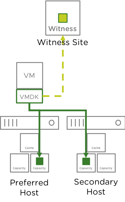
The illustration shows a storage policy that protect vSAN Objects across sites. This is the default protection policy used with vSAN 2 Node Clusters for versions 6.1 through 6.7.
vSAN 2 Node Clusters can support up to a single host failure.
It is important to remember that the vSAN Witness Host, residing in the Witness site, is a single host also.
The scenarios in this section will cover different failure behaviors.
Individual Drive Failure
What happens when a drive fails?
-
- vSAN will mark the component degraded and the VM will continue to run.
- Reads are immediately serviced from the alternate node
- The component will be rebuilt within the same host if there is an additional drive or disk group available.
- If there are no additional drives or disk groups available in the host, the component will only be rebuilt if the failed/isolated device comes back online.
- In cases where the component cannot be rebuilt, reads will continue to be serviced from the alternate host.

Goes Offline?
-
vSAN will mark the component absent and the VM will continue to run.
- Reads continue to be serviced from the alternate node
- After 60 minutes:
- The component will be rebuilt within the same host if there is an additional drive or disk group available.
- If there are no additional drives or disk groups available in the host, the component will only be rebuilt if the failed/isolated device comes back online.
- In cases where the component cannot be rebuilt, reads will continue to be serviced from the alternate host.
Host Failure and Network Partitions
What happens when a host goes offline, or loses connectivity?
A typical 2 Node vSAN Cluster configuration can be seen here:

Preferred Host Failure or Completely Partitioned
In the event the Preferred Host fails or is partitioned, vSAN powers the virtual machines running in that Host off. The reason for this is because the virtual machine's components are not accessible due to the loss of quorum. The vSAN 2 Node has now experienced a single Host failure. The loss of either Host in addition to the vSAN Witness is two failures, will take the entire cluster offline.

The Secondary Node will be elected as the HA leader, which will validate which virtual machines are to be powered on. Because quorum has been formed between the vSAN Witness Host and the Secondary Host, virtual machines on the Secondary Host will have access to their data and can be powered on.

Secondary Host Failure or Partitioned
In the event the Secondary Host fails or is partitioned, vSAN powers the virtual machines running in that host off. The reason for this is because the virtual machine's components are not accessible due to the loss of quorum. The vSAN 2 Node Cluster has now experienced a single site failure. The loss of either node in addition to the witness is two failures, will take the entire cluster offline.

The Preferred Host, will validate which virtual machines are to be powered on. Virtual machines that have been moved to the Preferred Host will now have access to their data and can be powered on.

vSAN Witness Host Failure or Partitioned
Virtual machines running in both nods of a 2 Node Cluster are not impacted by the vSAN Witness Host being partitioned. Virtual machines continue to run. The vSAN 2 Node Cluster has now experienced a single failure. The loss of either host in addition to the witness is two failures, will take the entire cluster offline.

In the event the vSAN Witness Host has failed, the behavior is the same as if the vSAN Witness Host has been partitioned from the cluster. Virtual machines continue to run at both locations. Because the 2 Node vSAN Cluster has now experienced a single site failure, it is important to either get the vSAN Witness Host back online or deploy a new one for the cluster.

When the existing vSAN Witness Host comes back online, metadata changes are resynchronized between the 2 Node vSAN Cluster sites and the vSAN Witness Host.
If a new vSAN Witness Host is deployed after 60 minutes the metadata changes will automatically be created on the vSAN Witness Host and synchronized across the 2 Node Cluster. If the new vSAN Witness Host is deployed before 60 minutes, selecting Repair Objects in the vSAN Health Check UI will be required to create the vSAN Witness Component metadata.
The amount of data that needs to be transmitted depends on a few items such as the number of objects and the number of changes that occurred while the vSAN Witness Host was offline. However, this amount of data is relatively small considering it is metadata, not large objects such as virtual disks.

VM Provisioning When a Host is Offline
If there is a failure in the cluster, i.e. one of the hosts is down; new virtual machines can still be provisioned. The provisioning wizard will however warn the administrator that the virtual machine does not match its policy as follows:

In this case, when one node is offline and there is a need to provision virtual machines, the ForceProvision capability is used to provision the VM. This means that the virtual machine is provisioned with a NumberOfFailuresToTolerate = 0, meaning that there is no redundancy. Administrators will need to rectify the issues on the failing site and bring it back online. When this is done, vSAN will automatically update the virtual machine configuration to NumberOfFailuresToTolerate = 1, creating a second copy of the data and any required witness components.
Multiple Simultaneous Failures
What happens if there are failures at multiple levels?
The scenarios thus far have only covered situations where a single failure has occurred.
Votes and their contribution to object accessibility
The vSAN Design Guide goes into further detail about how component availability determines access to objects. In short, each component has a vote, and a quorum of votes must be present for an object to be accessible. Each site will have an equal number of votes and there will be an even distribution of votes within a site. If the total number of votes is an even number, a random vote will be added.
In the illustration below, a 2 Node vSAN Cluster (4+4+1) has an object mirrored across hosts.

If the vSAN Witness Host fails, the vmdk is still accessible.

If the Secondary Node, or the link between the Nodes, were to also fail, the vSAN Objects would not be accessible

The proper mechanism to recover would be to bring the Secondary Node back online and ensure it can communicate with the Preferred Node. With the Preferred and Secondary Nodes online, vSAN Objects will be accessible, but will not have policy compliance.

The vSAN Witness Host may be brought back online, or a new vSAN Witness Host may be deployed.
When either the vSAN Witness Host or a replacement vSAN Witness Host is brought online, objects may be repaired through the vSAN Health Check UI to achieve policy compliance.

Improved resilience for simultaneous site failures
Often, administrators need to place a 2 Node cluster host in maintenance mode for upgrades or planned tests. One of the nodes can also go down due to unexpected reasons like power outages. During the time one of the hosts is offline the VMs will be running on the surviving host of the 2 Node cluster, during this time the cluster becomes more vulnerable to any additional failures. In vSAN 7 Update 3, if the cluster experiences a witness host fault after one of the hosts has already been deemed unavailable, vSAN will continue maintaining data availability for the workloads running inside the 2 Node cluster.
What are the changes in the voting mechanism?
In versions previous to vSAN 7 Update 3, if one of the nodes in the 2 Node cluster becomes offline or inactive, and then the witness host goes offline due to a planned or unplanned event, this would have resulted in the unavailability of the data residing on the remaining data node due to its insufficient number of votes to form a quorum.
This resilience enhancement has been achieved by modifying the voting mechanism in the cluster. These changes enable vSAN to assign most of the votes to the VM object replicas on the surviving host. These readjustments remove the dependency on the witness host. Thus, the remaining host objects can form a quorum immediately after the first host has been deemed offline, including being offline in maintenance mode, and maintain resilience for the VMs running inside the 2 Node cluster even if the witness site goes down unexpectedly. The original voting mechanism is restored once all the hosts are back to operational.
The graphics below showcases a possible voting mechanism for a single VMDK object. For simplicity we’re going to take an example with an object that has a RAID 1, Mirroring policy applied. Note that these vote numbers are only a representation of the voting ratio. As a starting point, both hosts' objects, on Site A and Site B, possess an equal number of votes, 1 vote each. The witness site object originally gets the most votes – 3 votes. As described, the adjustments in the voting mechanism will be triggered by a planned or unplanned site failure. After the fault event, most of the votes will be assigned to the remaining host objects, in this example, 3 votes will be assigned to Site A. Now, this site can form a quorum and maintain site resiliency for the VMs running inside the 2 Node cluster, even in case of an additional witness host failure. Here you can find a detailed demo describing two of the vSAN 7 Update 3 enhancements including site resilience for 2 Node clusters.

Fig. 1. Voting mechanism before a host failure

Fig. 2. Voting mechanism after a host and a witness host failure.
For more details, please review the "Failure Scenarios" section, sub-section "Improved resilience for simultaneous site failures in vSAN 7 Update 3"of the VSAN Stretched cluster guide, as the enhancement is applicable to both - 2 Node cluster and Stretched cluster.
Replacing a Failed vSAN Witness Host
Should a vSAN Witness Host fail in the vSAN 2 Node Cluster, a new vSAN Witness Host can easily be introduced to the configuration.
Replacing the vSAN Witness Host in vSAN 6.7 or higher using the vSphere Client
Navigate to Cluster > Configure > vSAN > Fault Domains & Stretched Cluster

Select "Change "
Use the Change Witness Host Wizard in the same fashion as adding an initial vSAN Witness Host.
Select the new vSAN Witness Host to be used

Select the 10GB disk for the cache device and the 15GB for capacity

Finish the wizard

Replacing the vSAN Witness Host in vSAN 6.6 or higher using the vSphere Web Client
Navigate to Cluster > Configure > vSAN > Fault Domains & Stretched Cluster

Select "Change Witness Host"
Use the Change Witness Host Wizard in the same fashion as adding an initial vSAN Witness Host.
Select the new vSAN Witness Host to be used

Select the 10GB disk for the cache device and the 15GB for capacity

Finish the Wizard.
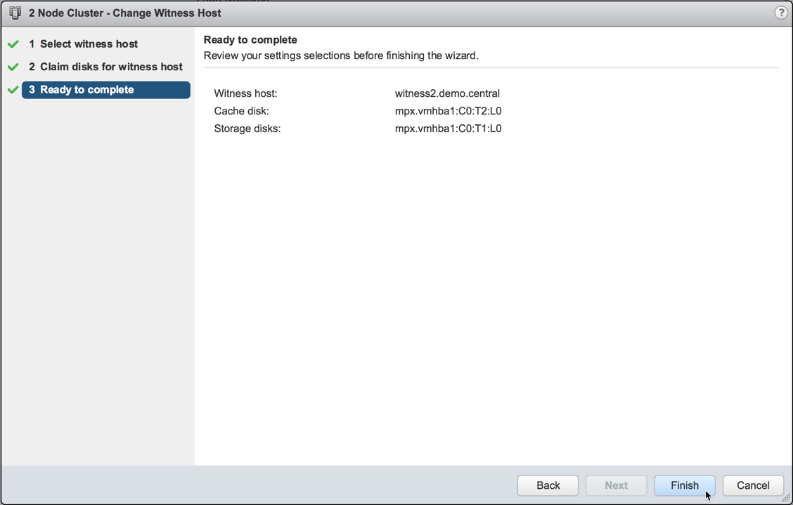
Replacing the vSAN Witness Host Pre-6.6
Navigate to Cluster > Manage > vSAN > Fault Domains.

The failing witness host can be removed from the vSAN Stretched Cluster via the UI (red X in fault domains view).

The next step is to rebuild the vSAN stretched and selecting the new witness host. In the same view, click on the “configure stretched cluster” icon. Align hosts to the preferred and secondary sites as before. This is quite simple to do since the hosts are still in the original fault domain, so simply select the secondary fault domain and move all the hosts over in a single click:

Select the new witness host:

Create the disk group and complete the vSAN Stretched Cluster creation.
On completion, verify that the health check failures have resolved. Note that the vSAN Object health test will continue to fail as the witness component of VM still remains “Absent”. When CLOMD (Cluster Level Object Manager Daemon) timer expires after a default of 60 minutes, witness components will be rebuilt on new witness host. Rerun the health check tests and they should all pass at this point, and all witness components should show as active.
Failure Scenario Matrices
Hardware/Physical Failures
| Scenario | vSAN Behaviour | Impact/Observed VMware HA Behaviour |
|---|---|---|
| Cache disk failure | Disk Group is marked as failed and all components present on it will rebuild on another Disk Group after 60 minutes. | VM will continue running. |
| Capacity disk failure (Dedupe and Compression ON) | Disk Group is marked as failed and all components present on it will rebuild on another Disk Group after 60 minutes. | VM will continue running. |
| Capacity disk failure (Dedupe and Compression OFF) | Disk marked as failed and all components present on it will rebuild on another disk after 60 minutes. | VM will continue running. |
| Disk Group failure/offline | All components present on the Disk Group will rebuild on another Disk Group after 60 minutes. | VM will continue running. |
| RAID/HBA card failure | All Disk Groups backed by the HBA/RAID card will be marked absent and all components present will rebuild on other Disk Groups after 60 minutes. | VM will continue running. |
| Host failure | Component on the host will be marked as absent by vSAN | VM will continue running if on the alternate host.
If the VM was running on the same host as the failure a HA restart of the VM will take place if HA is enabled. |
| vSAN Witness Host loss / failed / isolated from one or both nodes | vSAN Witness Host loss counts as a site (PFTT) failure, as such the cluster will be placed in a degraded state until the witness comes back online or is redeployed. | VM will continue running. |
| Node failure or partition, ISL failure / connectivity loss | Host is declared lost, quorum is established between the vSAN Witness Host and the remaining node. | VMs running on the partitioned/failed node are powered off.
HA will restart the VMs from the secondary fault domain/host on the preferred fault domain/host. If the preferred fault domain/host has failed, VMs will restart on the secondary fault domain/host. |
| Loss of both hosts | Cluster offline. | VMs stop running. HA cannot restart VMs until quorum is re-established. |
Nested fault domains for 2 Node clusters
vSAN 7 Update 3 introduces an additional level of resilience for the data stored in a 2 Node cluster by enabling nested fault domains on a per disk group basis. In case one of the disk groups fails, an additional copy of the data will remain available in one of the remaining disk groups.
Companies with many branch offices and remote offices are in search of a scalable and easy to maintain solution suitable for their edge deployments. Often, no trained admins are available at the edge location, thus, troubleshooting, replacements, hardware, and software upgrades might take longer than customers can afford. 2 Node clusters require two ESXi nodes per cluster located at the remote office and one witness host/appliance, deployed at the main data center. This configuration can maintain data availability even if one of the hosts in the cluster becomes unavailable. vSAN 7 U3 provides even higher resiliency by introducing the nested fault domain feature for 2 Node clusters to help ROBO businesses have broader control in case of more than one failure.

Fig. 1. Nested fault domains for 2 Node clusters
This new feature is built on the concept of fault domains, where each host or a group of hosts can store redundantly VM object replicas. In a 2 Node cluster configuration, fault domains can be created on a per disk-group level, enabling disk-group-based data replication. Meaning, each of the two data nodes can host multiple object replicas. Thanks to that secondary level of resilience the 2 Node cluster can ensure data availability in the event of more than one device failure. For instance, one host failure and an additional device or disk group failure, will not impact the data availability of the VMs having a nested fault domain policy applied. The vSAN demo below shows the object replication process across disks groups and across hosts.
Requirements
A minimum of 3 disk groups per host will be required to serve the nested level of fault tolerance. For example, in case we have failures to tolerate “FTT = 1 Failure – RAID- 1”, vSAN will need at least one disk group per each of the two data replicas and one disk group for the witness component. A new type of SPBM policy - “Host mirroring - 2 node cluster” is created to enable the replication inside a single host in a 2 Node cluster. The principles of this data placement logic are similar to the ones used for vSAN stretched clusters. The primary level of resilience in stretched clusters is on a per-site level, while in a 2 Node cluster it is on a per-host level. With this new nested fault domain feature, a secondary level of protection for 2 Node clusters is also available like the one for stretched clusters, but here it is on a per-disk group level, instead on a per-host level as for stretched clusters.
A few things need to be highlighted here, like the fact that RAID-6 is not supported since the maximum number of disk groups that can be created is 5, and 6 is the minimum required to apply RAID-6. If RAID-0 has been initially applied, a secondary level of resilience will not be supported. An efficient way for the admin to balance resiliency and performance is to apply different policies depending on the needs of the corresponding VMs or VM objects.