
vSAN Migration Guide
What are the top considerations when migrating a VM to a vSAN cluster?
Migrating to the Express Storage Architecture in vSAN 8
vSAN 8 introduces a new architecture known as the vSAN Express Storage Architecture (ESA). As an optional architecture to the Original Storage Architecture (OSA) found in previous versions of vSAN, as well as vSAN 8, the ESA delivers all-new capabilities not possible with the OSA. The ESA processes and stores data in a new way, using an approach designed specifically for high-performing NVMe-based storage devices, fast processors, and high-throughput networks.
The vSAN Express Storage Architecture (ESA) in vSAN 8 does not have a direct, in-place upgrade path for a cluster running the Original Storage Architecture (OSA). To learn how to transition to the vSAN ESA, see "Migrating to the Express Storage Architecture in vSAN 8."
Migration from VMFS/NFS
Migration strategies and options for vSAN are numerous depending on your environment and implementation of vSphere. This article will discuss the native options for migrating virtual machine workloads to vSAN. The methodologies presented are valid for vSAN in general, vSAN Ready Nodes clusters as well as hyperconverged infrastructure (HCI) appliances such as Dell EMC VxRail™ Appliances.
Minimal or no reconfiguration will be emphasized as well as maintaining virtual machine uptime, avoiding downtime where possible.
While third-party options and solutions, such as backup, recovery, and replication are valid options; those items are out of scope for this document due to extra cost and resources involved to deploy, configure and implement. Recommendations presented are based on current VMware best practices.
We will cover topics including migration within an existing data center with both shared and non-shared storage, from physical servers direct to vSAN and migrating between physically disparate data centers.
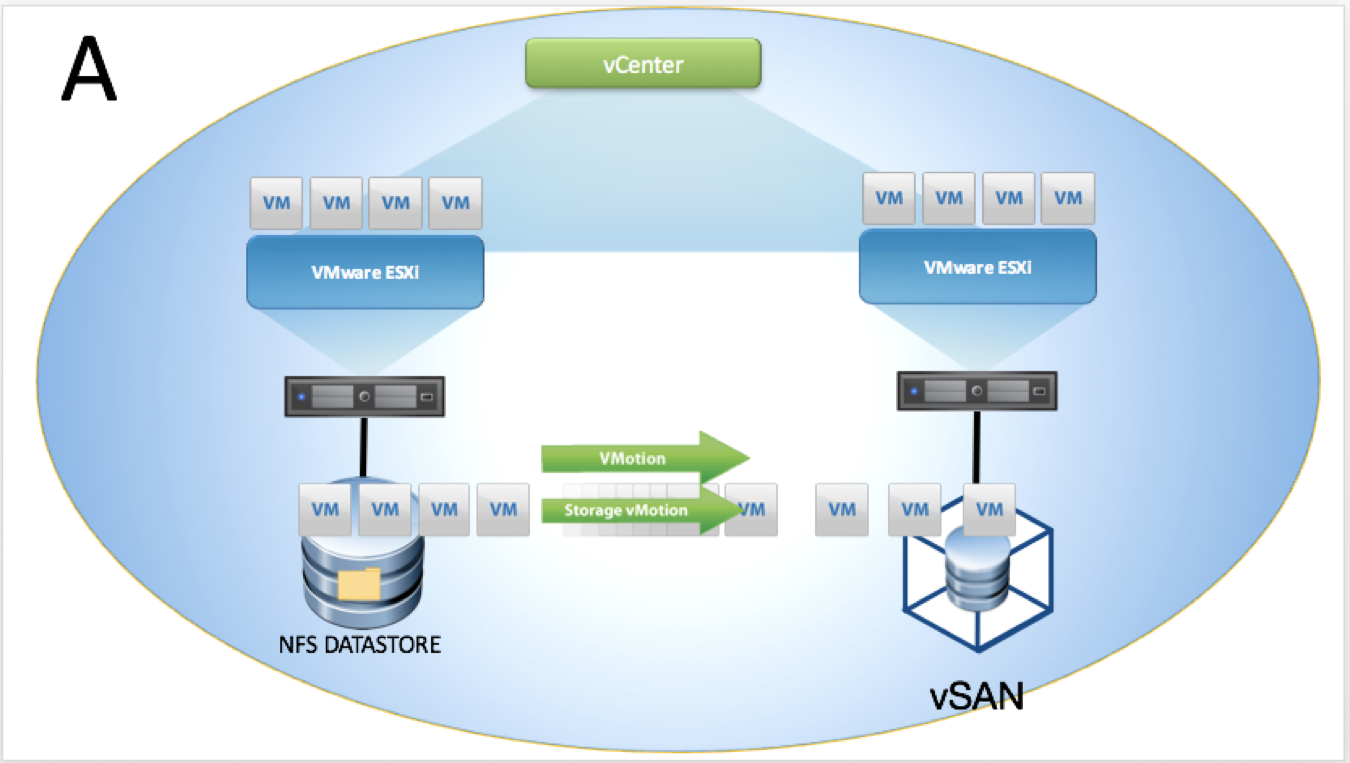
Modes of vMotion
Migration of a virtual machine can be either compute only, storage only or both simultaneously. Also, you can use vMotion to migrate virtual machines across: vCenter Server instances; virtual and physical data centers; and subnets. vMotion operations are transparent to the virtual machine being migrated. If errors occur during migration, the virtual machine reverts to its original state and location.
Compute vMotion
Compute mode vMotion operations usually occur within the same logical vSphere cluster, The two hosts involved in a vMotion can, however, reside in separate logical or physical clusters.
Storage vMotion
Storage vMotion is the migration the files, that belong to a running virtual machine, residing on one discrete datastore to another discrete datastore.
Combined vMotion
When you choose to change both the host and the datastore, the virtual machine state moves to a new host and the virtual disks move to another datastore.
Shared-nothing vMotion
Also known as vMotion without shared storage, allows you to utilize vMotion to migrate virtual machines to a different compute resource and storage simultaneously. Unlike Storage vMotion, which requires a single host to have access to both the source and destination datastore, you can migrate virtual machines across storage accessibility boundaries.
vMotion does not require shared storage. This is useful for performing cross-cluster migrations when the target cluster machines might not have access to the source cluster's storage.
Cross-vCenter vMotion
Also known as vMotion between vCenter instances and long-distance vMotion allows for the migration of VMs across vCenter boundaries both within and outside an SSO domain as well as over links with up to a 150ms RTT (Round Trip Time).
Migration between two vCenter servers within the same SSO domain is accomplished within the vSphere web interface, which leverages enhanced linked mode (ELM). While migration between two vCenter servers that are members of different SSO domains require APIs/SDK initiation.
Migration of VMs between vCenter instances moves VMs to new virtual networks; the migration process issues checks to verify that the source and destination networks are similar. vCenter performs network compatibility checks to prevent the following misconfigurations:
- MAC address incompatibility on the destination host
- vMotion from a distributed switch to a standard switch
- vMotion between distributed switches of different versions
- vMotion to an isolated network
- vMotion to a distributed switch that is not functioning properly
Despite these checks, however, it is prudent to ensure that:
- Source and destination distributed switches are in the same broadcast domain
- Source and destination distributed switches have the same services configured
Preparation
To allow for a successful migration of VM workloads onto vSAN a review of your current virtual infrastructure is advised. Extension of the existing vMotion network into the new vSAN environment is required, allowing for migration of the VM workload from its current location to the new vSAN infrastructure.
There are many possible valid configurations for compute and storage, but for migration into vSAN there are specific requirements listed below:
Source Environment
Licensing
- Essentials Plus or higher for vMotion feature
- Enterprise Plus or higher for Cross-vCenter vMotion
- Enterprise Plus for long-distance vMotion
NTP
- Uniform time synchronization is required for the vCenter and ESXi hosts
vCenter Topology
- One vCenter, one SSO domain
- Two vCenters, one SSO domain
- Two vCenters, two SSO domains
Networking
- L2 (Layer two) adjacency between source and destination VM networks
- VSS or VDS configuration at, or greater than, version 6.0.0
ESXi
- ESXi v6.0 or above for Cross-vCenter migration
Clusters
- If EVC (Enhanced vMotion Compatibility) is enabled, the source cluster must be at a lower or equal EVC level to the target cluster
Virtual Machine
- Application dependencies
- RDMs – either converted to VMFS or migrated to in-guest iSCSI
- VMTools will require an update if VM is migrated to a newer ESXi version
Destination Environment
The destination vSphere environment requires network access for the virtual machine matching the source environment, for example, VLAN access and IP addresses must be considered. Additionally, advanced configurations such as DRS affinity rules, and Storage Policies will need to be re-created on the target environment if they are still required.
Cold Migration Considerations
While this operation can be done "live," organizations may choose to migrate with VMs powered off. vMotion of a powered-off or suspended virtual machine is known a cold migration and can be utilized to move virtual machines from one data center to another. A cold migration can be operated manually or via a scheduled task.
By default, data migrated in a cold state via vMotion, cloning, and snapshots is transferred through the management network. This traffic is called provisioning traffic and is not encrypted.
On a host, you can dedicate a separate VMkernel interface to provisioning traffic, for example, to isolate this traffic on another VLAN. A provisioning VMkernel interface is useful if you plan to transfer high volumes of virtual machine data that the management network cannot accommodate or have a dedicated network for migration data between clusters or datacenters.
For information about enabling provisioning traffic on a separate VMkernel adapter, see the vSphere networking documentation .
Migration Scenarios
The previous sections highlighted Compute, Network and Virtual Machine configuration recommendations and requirements; we will now focus on the vCenter and SSO configuration. The main migration topologies supported are listed below.
- Topology A: Single vCenter, Single SSO domain
- Topology B: Two vCenters, Single SSO domain
- Topology C: Two vCenters, Two SSO domains
We recommend that the source and destination vCenter servers be updated to the most recent version possible.
In addition to the supported topologies, there are source and destination vCenter Server versions that need to be adhered to:
| Source vCenter version | Target vCenter version | Supported | Method |
| 6.7 | 6.7 | Yes | UI and API |
| 6.7 | 7.0 | Yes | API |
| 7.0 | 6.7 | No | N/A |
| 7.0 | 7.0 | Yes | UI and API |
Single vCenter, Single SSO Domain
The migration is initiated from the vSphere web interface. As both clusters are in the same vCenter, no special considerations need to be made. A migration of both compute resource and storage takes place with no shared storage available across both clusters. The source datastore is not accessible from the target cluster.
Two vCenters, Two SSO Domains
The migration is initiated from the API (via PowerCLI), the vCenter servers are in different SSO domains. A migration of both compute resource and storage takes place with no shared storage available across both clusters. The source datastore is not accessible from the target cluster.

Two vCenters, Single SSO Domain
The migration is initiated from the vSphere web interface, Enhanced Linked Mode (ELM) is utilized meaning vCenter servers are in the same SSO domain. A migration of both compute resource and storage takes place with no shared storage available across both clusters. The source datastore is not accessible from the target cluster.

Limits and Considerations
Simultaneous Migrations
vCenter places limits on the number of simultaneous VM migration and provisioning operations that can occur on each host, network, and datastore. Each operation, such as a migration with vMotion or cloning a VM, is assigned a resource cost. Each host, datastore, or network resource, has a maximum cost that it can support at any one time. Any new migration or provisioning operation that causes a resource to exceed its maximum cost is queued until the other in-flight operations reach completion.
Each of the network, datastore, and host limits must be satisfied for the operation to proceed. vMotion without shared storage, the act of migrating a VM to a different host and datastore simultaneously, is a combination of vMotion and Storage vMotion. This migration inherits the network, host, and datastore costs associated with both of those operations.
Network Limits
Network limits apply only to migrations with vMotion. Network limits depend on the version of ESXi and the network type.
| Operation | ESXi Version | Network Type | Maximum concurrent vMotions per Host |
| vMotion | 5.0, 5.1, 5.5, 6.0, 6.5 | 1 GbE | 4 |
| vMotion | 5.0, 5.1, 5.5, 6.0, 6.5 | 10 GbE | 8 |
Considerations must be made for uplink speed of the NIC assigned to the vMotion service. For example, if you are using vMotion from a 1GbE source vMotion network to a vSAN Target destination with 10GbE, you will be throttled to the lower speed of the two.
Datastore Limits
Datastore limits apply to migrations with vMotion and with Storage vMotion. Migration with vMotion and Storage vMotion have individual resource costs against a VM's datastore. The maximum number of operations per datastore are listed below.
| Operation | ESXi Version | Max per Datastore |
| vMotion | 5.0, 5.1, 5.5, 6.0, 6.5 | 128 |
| Storage vMotion | 5.0, 5.1, 5.5, 6.0, 6.5 | 8 |
Host Limits
Host limits apply to migrations with vMotion, Storage vMotion, and other provisioning operations such as cloning, deployment, and cold migration. All hosts have a maximum number of operations they can support. Listed below are the number of operations that are supported per host - note that combinations of operations are allowed and are queued and executed automatically by vCenter when resources are available to the host.
| Operation | ESXi Version | Max operations per Host |
| vMotion | 5.0, 5.1, 5.5, 6.0, 6.5 | 8 |
| Storage vMotion | 5.0, 5.1, 5.5, 6.0, 6.5 | 2 |
| Shared-Nothing vMotion | 5.1, 5.5, 6.0, 6.5 | 2 |
| Other provisioning operations | 5.0, 5.1, 5.5, 6.0, 6.5 | 8 |
References
PowerCLI
An example migration script for moving VMs between vCenters and SSO domains, using PowerCLI, is shown below. The script moves myVM from myVC1 to myVC2 on to target port group myPortGroup and datastore vsanDatastore .
Connect-VIServer 'myVC1' -Username <username> -Password <pass>
Connect-VIServer 'myVC2' -Username <username> -Password <pass>
$vm = Get-VM 'myVM' -Location 'hostOnVC1'
$destination = Get-VMHost 'hostOnVc2'
$networkAdapter = Get-NetworkAdapter -VM $vm
$destinationPortGroup = Get-VDPortgroup -VDSwitch 'VDSOnVC2' -Name 'myPortGroup'
$destinationDatastore = Get-Datastore 'vsanDatastore'
$vm | Move-VM -Destination $destination -NetworkAdapter $networkAdapter -PortGroup $destinationPortGroup -Datastore $destinationDatastore
More information and detail on the Move-VM command can be found here: https://blogs.vmware.com/PowerCLI/2017/01/spotlight-move-vm-cmdlet.html
KBs and Whitepapers
The vCenter Server Host Management guide covers:
- vMotion Shared Storage Requirements
- vSphere vMotion Networking Requirements
- Networking Best Practices for vSphere vMotion
- Enhanced vMotion Compatibility
“EVC and CPU Compatibility FAQ” - https://kb.vmware.com/kb/1005764
“Enhanced vMotion Compatibility (EVC) processor support" - https://kb.vmware.com/kb/1003212
“Long Distance vMotion Requirements” - https://kb.vmware.com/kb/2106949
“Cross vCenter vMotion Requirements in vSphere 6.0” - https://kb.vmware.com/kb/2106952
HCI Mesh Migration Considerations
vSAN HCI Mesh offers new ways to migrate data to a vSAN cluster. Previously there were two options to vMotion a virtual machine to a vSAN cluster.
1. Extend the existing storage to the vSAN cluster (allowing for a regular vMotion, followed by a storage vMotion after the fact).
2. Use a shared nothing vMotion.
There was not an option to continue to use the existing compute cluster, while leveraging a vSAN cluster for storage.
Now with HCI mesh, a remote vSAN datastore can be mounted, allowing for storage vMotion to be performed. Beyond separating compute from storage, this also allows for breaking up the compute and storage vMotion without needing to extend the legacy storage into the vSAN cluster.

Migrating RDMs to vSAN
Traditionally, there have been two particular reasons why people use RDMs in a vSphere environment: To allow the addition of disks to VMs that were larger than 2TB in size; For shared-disks, such as quorum and shared-data drives for solutions like SQL FCI, Windows CSVs.
The first of these is trivial to address - the limitation for 2TB VMDKs was removed with ESXi 5.5 and VMFS-5. The limit is now the same as with RDMs at 62TB, and as such RDMs should no longer be considered for this use-case.
The second is the main reason RDMs may still be in use today: Shared-disk quorum and data between VMs.
In this section, we will address the migration of non-shared disk RDMs to native vSAN objects, as well as the transition of shared-disks from the legacy RDM based approach to in-guest iSCSI initiators.
Migrating non-shared RDMs to vSAN
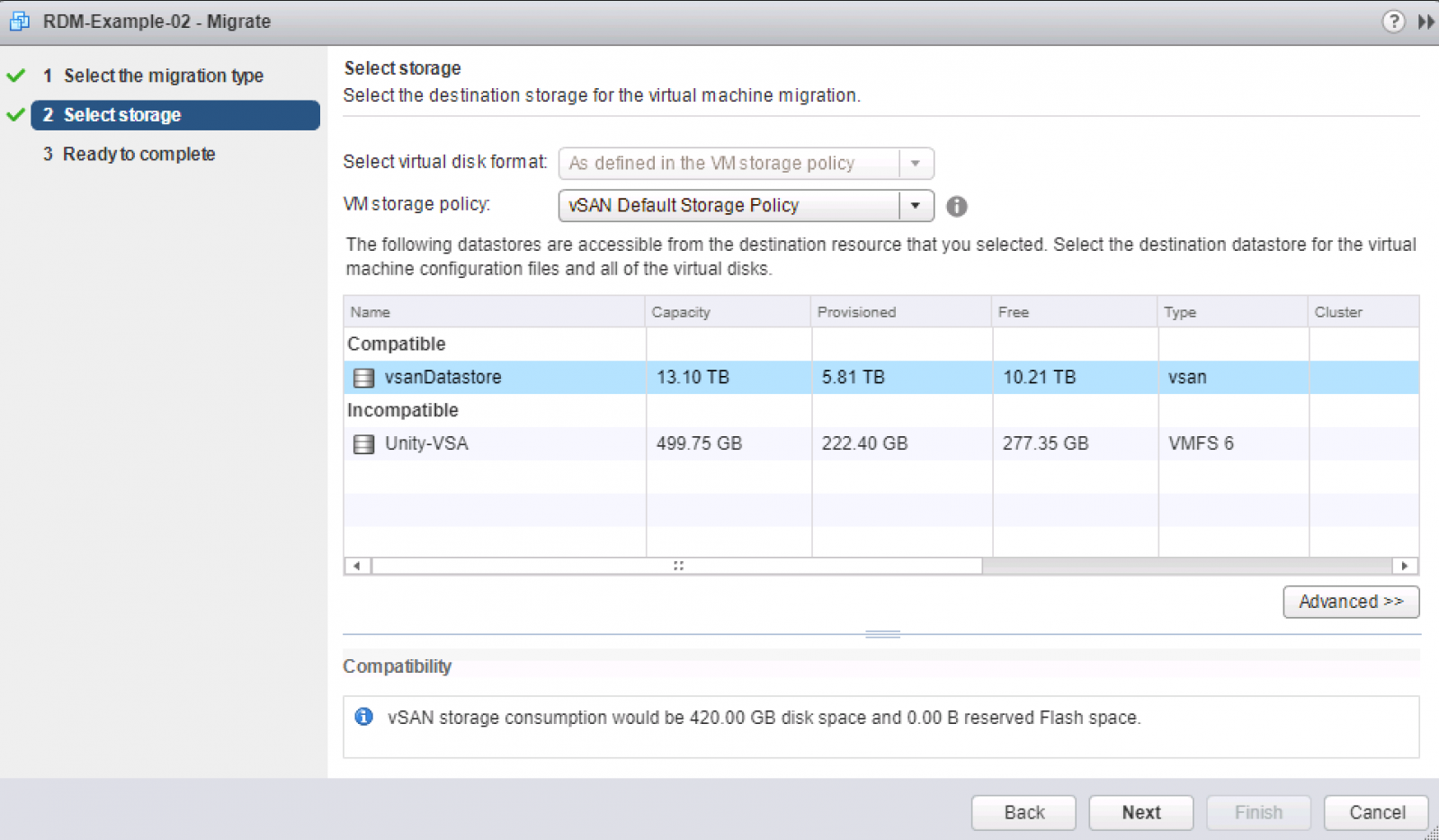
Non-shared RDMs are trivial to migrate to vSAN, as they can be live storage vMotioned to VMDKs. To start with your RDMs must be in virtual compatibility mode to leverage a storage vMotion conversion to VMDK. After converting any physical mode RDMs you have to virtual mode, you may then initiate a storage vMotion to vSAN directly. You can see in the below example, I svMotion a VM with a virtual mode RDM, live, to a vSAN datastore and its RDM is converted to a native vSAN object:

Choose Migrate... and Change storage only:

Change the policy to your chosen SPBM policy and choose the target vSAN datastore:

After the migration has completed, you will notice that the disk type is no-longer RDM, rather it is listed as a VDMK and is editable as it is not a first-class citizen of the datastore:

Physical Mode
If you have physical mode RDMs they cannot have the LUN contents migrated live and would require a cold migration. Under the consideration that most physical mode RDMs are created for large data sets, to minimise downtime from a cold migration we recommend converting the RDMs to virtual mode first, then carrying out the necessary storage vMotion to convert the disk to a VMDK which can be done while the VM is operational.
The process for this can be found in our KB here: KB 1006599
Bus-sharing SCSI Controllers
N.B: If any of the SCSI controllers in the VM are engaged in bus-sharing (they shouldn't be if the disks are not shared between VMs), whether physical or virtual mode, the storage vMotion will fail validation and not allow the migration to vSAN with the below error:

Migrating Windows shared disk quorum to File Share Witness
Shared disk RDMs in either virtual or physical compatibility mode have been enabled typically to provide support for guest OS clustering quorum mechanisms. Since Windows Server 2008, the need for a dedicated quorum shared disk has not been necessary. Instead, you can use a FSW (File Share Witness), the FSW can be a standard Windows server on a vSAN datastore.
File Share Witness fault-detection provides the same level of redundancy and failure detection as traditional shared-disk quorum techniques, without the additional operational and installation complexity that those solutions command.
Migration
Below you can see I have a SQL FCI cluster with two nodes, currently utilizing a shared-disk for cluster quorum:
.png)
We are going to convert this cluster to File Share Witness quorum, I have a file server in the environment (file01) and have created a standard Windows file share on it called: sql-c-quorum. N.B: This can be done live and is not service affecting.
Firstly, right click on the cluster and got to More Actions -> Configure Cluster Quorum Settings...
.png)
Then we will select "select the quorum witness":
.png)
Tell the cluster we are going to use a FSW:

Insert the file share we configured when prompted:

You will see a dialogue telling you that the cluster voting is enabled and was successful:

We can then verify we are operating in FSW mode on the main dialogue of the Failover Cluster Manager:

The VM no longer requires the RDMs used for cluster quorum or voting and they can be removed - this VM can now be migrated to vSAN by a simple storage vMotion and no downtime is required for the entire operation.
Migrating VMs with shared RDMs to vSAN
Shared RDMs have traditionally been an operational blocker to any migration or maintenance due to the complexity they create in an environment as well as the version dependencies they introduce and specific VM configurations they command. Organizations may wish to simplify their operations by having their VMs all operating under a single compute cluster with homogenous configurations at a vSphere level.
Detailed below is the process for migrating VMs with existing shared RDMs, from physical and virtual mode RDMs to instead using in-guest iSCSI initiators; This allows clustered VMs to be migrated into a vSAN environment to reduce operational complexity while leaving data in place on the existing SAN.
Example Setup
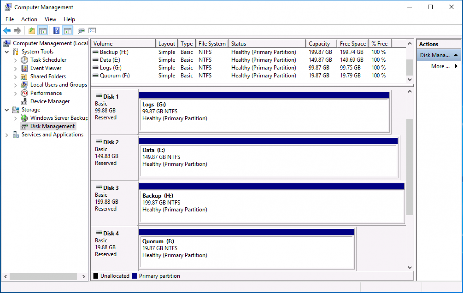
The use case covered is a WSFC (Window Server Failover Cluster) for a SQL FCI. In the below figure; there are three disks shared between the VMs for data access for: SQL Data, Logs, and Backups. Volumes presentation to the VM utilizes physical mode RDMs.

Figure 1 - Computer Management layout of cluster disks
Note: in the below example, the RDMs are in physical mode and are on Virtual Device Node; "SCSI controller 1". This information is essential to record for later as it will be necessary to remove this SCSI controller after removing the RDMs from the VM configuration.

Figure 2 - Disk attachment via physical mode RDMs
As a point of reference, RDMs are provided in this environment via an EMC Unity array with iSCSI connectivity on four uplink ports (Ethernet Port 0-3) with IPs of 10.0.5.7-10 respectively.

Figure 3 - iSCSI target connectivity on the array side
Preparation
To migrate existing RDMs, whether in physical mode or virtual mode the simplest option is to move the LUNs to an in-guest iSCSI initiator. Given RDMs are simply raw LUNs mapped through to a VM directly, storage presentation to the VM remains the same. VMs will have the same control over LUNs as they would have with an RDM and application operations will be unaffected by the migration.
In preparation, there are a few steps that must be completed on each VM in the cluster to allow for iSCSI connectivity to the SAN presented LUNs. Firstly, we will need to add a NIC connected to the iSCSI network to the VM.

Figure 4 - iSCSI network attached to VM via separate NIC
Next, the Windows iSCSI Initiator needs to be initialized. When prompted to have the iSCSI service start automatically on boot, select Yes.

Figure 5 - iSCSI initiator service auto-start prompt
In the following window, add one of the SAN's iSCSI targets into the Quick Connect section of the dialogue box. There is no need to add every target here; after MPIO is configured the array should communicate all target paths that can be used for LUN connectivity to the iSCSI Initiator, providing load balancing and failover capabilities.

Figure 6 - Adding in iSCSI targets to Windows iSCSI Initiator
At this point, you can apply MPIO policies specific to your array and OS version. Refer to your vendor's documentation for configuring MPIO in a Windows environment. Next, add the VM’s iSCSI initiator into the SAN’s zoning policy for the RDM LUNs. This again will vary from vendor to vendor. You can see below that the host object has been created on the SAN and has been given access to the three LUNs that are used for shared data between VMs.

Figure 7 - Allowing the iSCSI initiator access to the RDM LUNs
VM RDM Reconfiguration
At this point, migration from RDM to in-guest termination can begin. It would be prudent to start with the secondary node in the cluster, and given that WSFC is not transparent during role transferral, carrying out this work during a maintenance window is advised. Firstly, place the node undergoing reconfiguration into the "Paused" mode from the Failover Cluster Manager console, choosing to "Drain Roles" during maintenance.
.png)
Figure 8 - Pausing node membership in a WSFC
Shut down the secondary VM, and remove the RDMs and the shared SCSI controller from it. It is important to note that when you are deleting the disks from this node that you should not click "delete from datastore", remember: These are still in use by the primary node in the WSFC. Navigate to the VM in the vSphere Web Client and choose "Edit Settings" from here remove the disks and click "Ok."

Figure 9 - Removing RDMs from VM configuration on the secondary node
It is necessary to enter "Edit Settings" once more, now that the bus-sharing SCSI controller we recorded at the start is unused, and remove it. N.B: using controller SCSI0:* is not supported for shared/clustered RDMs, so RDMs should always be on a tertiary SCSI controller - you can verify this by checking the sharing mode on the controller.

Figure 10 - Removing the bus-sharing SCSI controller previously used by the RDMs
Power up the secondary VM and log in. Currently, the shared disks are not presented to the VM. Open up the iSCSI Initiator dialogue; your targets should all have connected at this point.

Figure 11 - iSCSI targets all reconnected on boot
Navigate to the "Volumes and Devices" section, and click "Auto Configure", this will mount the disks and display their MPIO identifiers in the Volume List.

Figure 12 - Volume Auto Configure list
Opening up the Windows disk management dialogue, you should now be able to see the disks connected but in the "Reserved" state. The reserved and offline state is expected, as this node is not the active node in the cluster, once a role transfer is complete you will see these disks listed via their volume identifier (D:\, E:\, F:\). Right-clicking on one of the disks and selecting "Properties" you will be able to see each disk's LUN ID as well as specifics on MPIO, multi-pathing policies, and partition type.

Figure 13 - Disk management dialogue showing the disks re-presented via iSCSI
Reintroduce the VM into the WFSC, open the Failover Cluster Manager and right-click the secondary node that has been undergoing maintenance, choose "Resume" selecting "Do not fail back roles".

Figure 14 - Adding the secondary node back into the WSFC
Ensure the WSFC console says the cluster is healthy, that both nodes are "Up" and transfer any roles from primary to secondary. The disks will automount via iSCSI at this time as the volume signature has remained the same. To transfer the roles over to the secondary node navigate to "Roles," right click, choose "Move" and "Select Node...", then choose the reconfigured node.
.png)
Figure 15 - Transferring roles over to the secondary node
Ensure your services are operating as expected, as mentioned earlier, in disk manager on the secondary node now, volumes will be listed but, with their volume identifiers.

Figure 16 - Disk manager showing the volumes as active and identified correctly
As before, enter the node to be migrated into "Paused" mode and choose "Drain Roles," then shut down the VM.

Figure 17 - Draining roles from the node to undergo maintenance
In the vSphere console, locate the VM (in this case; sql-c-01) and "Edit Settings". Remove the RDMs as before, but this time choose “delete from datastore,” this is safe to do as no other nodes are actively using these RDM pointer files anymore. Note; choosing "delete from datastore" does not delete data from the underlying LUN, which remains unaffected, this operation only removes the RDM pointer files from the VMFS upon which, they are situated.

Figure 18 - Removing and deleting RDM pointer files from the VM
As previously, navigate back into "Edit Settings" and delete the bus-sharing SCSI controller from the VM's configuration.

Figure 19 - Deleting the bus-sharing SCSI controller from the VM configuration
Power the VM on and open the iSCSI Initiator dialogue, verify that the targets are all listed as "Connected," navigate to the Volumes and Devices dialogue and click "Auto Configure". The volumes will now show up in the volume list, detailed by their MPIO identifier.

Figure 20 - Volume list detailing the MPIO identifiers for the iSCSI mounted volumes
Verify the disks show up in the Windows disk management snap-in and exhibit a "Reserved" and an offline state; again this is normal for the passive node in the cluster, only the active node mounts the volumes.

Figure 21 - Volumes are shown in disk manager as Reserved and offline
Open the Failover Cluster Manager dialogue again and navigate to the "Nodes" section, then resume the node's participation in the cluster, choosing "Do not fail back roles". Ensure the cluster is reformed healthily and both nodes indicate a status of "Up".

Figure 22 - WSFC is shown as healthy, and both nodes are in the "Up" state
At this point the WSFC disk migration is complete, both VMs have had their RDMs removed and now rely on in-guest iSCSI initiators for connectivity to shared disks. You can optionally transfer the WSFC roles back to the primary node, as a matter of preference.
Migration to vSAN
With the RDMs and bus-sharing SCSI controllers gone, we can now migrate the VM to vSAN. Note: This only migrates the VM's objects that are accessible to vSphere (VMX, swap, namespace, OS and non-shared VMDKs), the data for the shared disks still resides on the SAN. Please refer to the documentation on migrating a VM residing on VMFS/NFS to vSAN .
Rollback
In the circumstance you wish to migrate a VM back from the new mode of operation to the previous mode of operation, this is achievable by Storage vMotioning the VM from the vSAN datastore to a VMFS volume (required for RDM and bus-sharing compatibility) and following the below steps:
- Enter secondary node into "Paused" mode in WSFC
- Attach a bus-sharing SCSI controller to the secondary node in your chosen mode (physical/virtual)
- “Disconnect” active iSCSI sessions on the secondary node and remove all iSCSI Initiator configuration
- Connect RDMs to the secondary node in the same mode as the SCSI controller
- Check the volumes show up as "Reserved" in disk manager
- Failover WSFC roles from primary to secondary
- Enter primary node into "Paused" mode in WSFC
- Attach a bus-sharing SCSI controller to the primary node in your chosen mode (physical/virtual)
- “Disconnect” active iSCSI sessions on the primary node and remove all iSCSI Initiator configuration
- Connect RDMs to the primary node in the same mode as the SCSI controller
- Check the volumes show up as "Reserved" in disk manager
- Optionally, fail WSFC roles back to the primary node
Migrating Physical Workloads
Traditionally, there have been two particular reasons why people use RDMs in a vSphere environment: To allow the addition of disks to VMs that were larger than 2TB in size; For shared-disks, such as quorum and shared-data drives for solutions like SQL FCI, Windows CSVs.
The first of these is trivial to address - the limitation for 2TB VMDKs was removed with ESXi 5.5 and VMFS-5. The limit is now the same as with RDMs at 62TB, and as such RDMs should no longer be considered for this use-case.
The second is the main reason RDMs may still be in use today: Shared-disk quorum and data between VMs.
In this section, we will address the migration of non-shared disk RDMs to native vSAN objects, as well as the transition of shared-disks from the legacy RDM based approach to in-guest iSCSI initiators.
Migrating Physical Machines to vSAN
Virtual Mode
Non-shared RDMs are trivial to migrate to vSAN, as they can be live storage vMotioned to VMDKs. To start with your RDMs must be in virtual compatibility mode to leverage a storage vMotion conversion to VMDK. After converting any physical mode RDMs you have to virtual mode, you may then initiate a storage vMotion to vSAN directly. You can see in the below example, I svMotion a VM with a virtual mode RDM, live, to a vSAN datastore and its RDM is converted to a native vSAN object:

Choose Migrate... and Change storage only:

Change the policy to your chosen SPBM policy and choose the target vSAN datastore:
After the migration has completed, you will notice that the disk type is no-longer RDM, rather it is listed as a VDMK and is editable as it is not a first-class citizen of the datastore:

Physical Mode
If you have physical mode RDMs they cannot have the LUN contents migrated live and would require a cold migration. Under the consideration that most physical mode RDMs are created for large data sets, to minimise downtime from a cold migration we recommend converting the RDMs to virtual mode first, then carrying out the necessary storage vMotion to convert the disk to a VMDK which can be done while the VM is operational.
The process for this can be found in our KB here: KB 1006599
Bus-sharing SCSI Controllers
N.B: If any of the SCSI controllers in the VM are engaged in bus-sharing (they shouldn't be if the disks are not shared between VMs), whether physical or virtual mode, the storage vMotion will fail validation and not allow the migration to vSAN with the below error:

Orchestrating a mass migration to vSAN
Customers may wish to migrate hundreds, or thousands of VMs in a predictable and repeatable fashion, there are a number of ways to orchestrate the migration of large numbers of VMs, in this section we will cover the use of vSphere Replication and Site Recovery Manager to migrate large numbers of VMs in a similar fashion to a destination vSAN datastore.
Included in this coverage will be migrations to a vSAN datastore within the same datacenter (in a different cluster), in another vCenter and in a separate SSO domain.
vSphere Replication Interoperability
vSphere Replication supports vSAN in its entirety, as a source and destination datastore, Storage Policy Based Management is also supported with vSphere Replication, this allows customers to select disparate storage policies for source and destination datastores. Utilising storage policies in this way allows for storage efficiencies and cost savings.
For example: If at the primary site you have a large cluster utilizing a storage policy with FTT (Failures to tolerate) set to two, this allows for extra redundancy in the event of hardware failures. However, on the secondary site, a smaller cluster is utilized to save costs, VMs can be replicated with a storage policy specifying that FTT is set to one in order to save space on the smaller copies, the lower redundancy on the target site can save on ongoing capital and operational expenses while still providing an effective replication target for DR.
For more information on using vSphere Replication with vSAN, check out our Tech Note here .
Using SRM to migration virtual machines with vSphere Replication
Site Recovery Manager can be used in conjunction with vSphere Replication to migrate large numbers of VMs from an existing vSphere cluster to a new vSAN based one. This approach has the caveat of requiring VM downtime, however, can be used effectively when vMotion cannot be used or a large-scale migration of VMs is required, it is prudent to schedule this work during a maintenance window as it will require VM downtime.
Migrating large numbers of VMs
The migration of large numbers of VMs usually requires orchestration - SRM provides this capability when paired with vSphere Replication through the use of Protection Groups and Recovery Plans. It is important to note that in order to use SRM, the target vSAN cluster must be in a separate vCenter instance to the source vCenter, this is a limitation imposed by SRM from continuity and DR perspective.
vSphere Replication is limited to the recovery/migration of a single VM at once - SRM, conversely, can support concurrent migration of up to 2,000 VMs. SRM also provides the ability to orchestrate changes to VMs upon migration, for example, IP addresses if the migrations are across L3 (Layer 3 network) boundaries. In addition to these benefits, the migration plan can also be tested multiple times, with no ill-effect on production workloads, providing predictability and peace of mind to the process.
Demo
For a further understanding of SRM and vSAN interoperability, see this demonstration here.
It is wise to note that when replicating VMs with SRM and vSphere Replication that the policy selected when initially creating the replicas will be applied to the target VM container from then on, any subsequent changes to SPBM policy will only be replicated to the target VM once it has been recovered via a failover. Again, the testing process will allow you to account for this and model any rebuild traffic generated on the target side post-failover.
Migration testing
SRM offers the unique ability to test a migration or failover scenarios prior to actually enacting any change. This is especially useful in the case of large-scale migrations where multiple applications and dependencies are affected. The ability to test the logic and operation of a migration to a new environment prior to actually doing the migration is invaluable. With SRM, users can test their application group failovers by remotely connecting to a test bubble environment and ensuring applications are operating as expected prior to an actual production migration taking place.
Using HCX for migrations
NSX Hybrid Connect abstracts on-premises and cloud resources and presents them to applications as one continuous hybrid cloud. It provides high-performance, secure, and optimized multisite interconnects. The abstraction and interconnects create a highly secure infrastructure hybridity tunnel. With this hybridity tunnel, NSX Hybrid Connect facilitates secure and seamless application mobility and disaster recovery across on-premises vSphere platforms and VMware clouds . NSX Hybrid Connect is the most feature-rich tool currently available for Cloud Foundation workload mobility. This document explains how to install, configure, and use NSX Hybrid Connect with a Cloud Foundation site when connecting to a legacy vSphere environment.
Architecture
The NSX Hybrid Connect process begins with two vSphere sites, a source and a target. Each site has its own requirements for software installation. The target site requires the use of NSX; for this document, the target is a Cloud Foundation site. This site requires the installation of the NSX Hybrid Connect Manager components. The source site must also install the NSX Hybrid Connect Manager components. However, the installation package for this site is different from that of the target site. After the NSX Hybrid Connect target site has been installed and configured, a link will be provided to download the software components for the source site. NSX Hybrid Connect Manager does not require NSX but can be used in conjunction with it if NSX is available.

The following resources can be used to assist with migration:
Native WSFC support on vSAN using iSCSI Target
vSAN provides support for Windows Server Failover Clusters (WSFC). In vSAN 6.7 U3, support of WSFC is achieved through native SCSI-3 persistent reservations (SCSI3-PR). The application clustering abilities of WSFC require a shared disk in order to determine ownership across the application cluster. With vSAN 6.7 U3, VMs running WSFC can use a shared VMDK on a vSAN datastore.
The support of WSFC through SCSI3-PR supersedes previous methods of support for WSFC (vSAN 6.7 and 6.7 U1), which was achieved through the vSAN iSCSI services. For vSAN 6.7 U3 onward, using native SCSI-3 persistent reservations should be the only method used for WSFC servers and their shared disks.
For application clustering like WSFC, native support of SCSI-3PR simplifies design and administration, reduces performance overhead, offers full interoperability with vSAN features, and provides a consistent experience whether the workload is running on-premises, or in VMC on AWS.
Reference Architecture
The vSAN solutions team have developed a reference architecture for two WSFC roles (Scale-Out File Server and SQL FCI) on vSAN using the iSCSI target service, and is available to view here . This is a very useful resource if you want to learn best practices when it comes to planning and scaling a production deployment that uses WSFCs on vSAN. In addition to the reference architecture, a KB is also available here .
Demonstration
A demonstration outlining a total host failure that is serving IO to a SQL FCI instance running on vSAN is available to view below. It shows the environment configuration, database load testing as well as the failure and transparent recovery processes that take place when WSFC are used with the vSAN iSCSI service.
Concepts and Architecture
When configuring iSCSI targets within Windows that are resident on a vSAN cluster it is important to take note of the configuration maximums supported for the vSAN iSCSI Target service when used in conjunction with WSFCs.
A maximum of 16 targets each with 16 LUNs are supported when used with WSFCs in order to support transparent failover within Windows timeouts. In addition, a maximum of 128 iSCSI sessions per host is supported.
As such, when adding targets to Windows clusters we recommend only adding enough to satisfy the SPBM requirements (add FTT+1 vSAN iSCSI targets to each Windows iSCSI initiator).
A number of examples are illustrated below using the FTT+1 calculation, where SPBM is configured with:
- FTT=1 - add two targets to the Windows iSCSI initiator.
- FTT=2 - add three targets to the Windows iSCSI initiator.
- FTT=1, multiple fault domains - add two targets per fault domain to the Windows iSCSI initiator.
- FTT=2, multiple fault domains - add three targets per fault domain to the Windows iSCSI initiator.
These configurations ensure that the iSCSI targets will always be available as long as the SPBM policy is not violated. It is not necessary to configure more than FTT+1 targets in the Windows iSCSI Initiator as the FTT level of the vSAN objects defines the data availability level, exceeding this would just ensure the iSCSI target is available even though the data would not be.
Configuration
vSAN
In order to take advantage of the support for WSFC on vSAN we need to enable the iSCSI target service within the vCenter UI. This can be found by navigating to the vSAN cluster -> Configure -> iSCSI Target Service. From here, click “Enable” as shown below to configure the service on all hosts in the cluster.

You will be prompted for some information on how the iSCSI target service should be set up, we recommend using a dedicated vmkernel port for iSCSI target traffic (preferably on a dedicated physical NIC) – it is important to note down the IPs associated with these vmks as they will need to be put into the Windows iSCSI initiator later in the process.
At this point you can choose to change the SPBM policy associated with this target, however this can be changed at any time in the future as with all vSAN native objects.

After clicking Apply the option to create a new iSCSI Target will be shown, for this example we will configure a single iSCSI target with four LUNs attached to it.

The configuration we are using in this example is shown below, we have given the target an Alias to make it easy for us to identify – as well as setting the storage policy and vmkernel port we will use. (Note: the iqn section will automatically get filled in).

Within the target we will now be able to setup the LUNs to be presented to the Windows iSCSI initiator by clicking the “Add” button under vSAN iSCSI LUNs.

As an example I have filled out a Quorum disk’s configuration below, this would simply be repeated for every disk to be presented (in this case, four disks: logs, backups, data and quorum).

Configuration up to this point has been the same as it is when you configure the vSAN iSCSI Target normally and follows our documentation found here .
If desired, initiator groups can be set up to restrict access to targets to specific groups of hosts – if none are set then all hosts can see all vSAN presented iSCSI targets. For the sake of simplicity in this document, we will be using the default and allowing visibility to all iSCSI targets from all hosts.
Windows
Within windows there are a few things that need to be set up, assuming the Windows instances are fresh installations they will need the iSCSI initiator service enabled, MPIO and Windows Server Failover Cluster features enabled and MPIO settings brought in line with our supported figures.
We have made an automated script that will do all of these requiring just a single reboot of the target Windows machine, it is available here .
If you prefer to manually configure your windows instances the configuration steps are listed below.
Open Windows Server Manager and click Manage -> Add Roles and Features and add the “Failover Clustering” and “Multipath I/O” features.

Allow installation to complete and navigate to the Windows Start menu and search for “iSCSI Initiator” and open it – you will be prompted if you want the service to start with Windows, again, click yes.
After completing this action, once again navigate to the Start menu and open the “MPIO” service. Click the “Discover Multi-Paths” tab and check the “Add support for iSCSI devices” checkbox. Reboot the guest when prompted.

Once the guest has rebooted, open a PowerShell command prompt and paste in the following:
Set-MPIOSetting -CustomPathRecovery Enabled -NewPathRecoveryInterval 20 -NewRetryCount 60 -NewPDORemovePeriod 60 -NewPathVerificationPeriod 30
This command sets iSCSI path timeouts and retry counts and is required in order for WSFC to be supported on the vSAN iSCSI Target service – a KB detailing what each parameter is can be found here (TONY’S KB HERE).
If you want to check what your current MPIO settings are, this can be done by running the following command in PowerShell:
Get-MPIOSetting

Given the vSAN iSCSI Target service only support “fail-over only” as the path selection policy within windows we need to set that explicitly via CLI in windows with the following command:
mpclaim -l -t "VMware Virtual SAN “ 1
Again, as before the current MPIO claim failover policies can be listed by running the following (correct configuration is indicated by “LB Policy”: “FOO”):
mpclaim.exe -s -t

At this point we are ready to add targets to the Windows iSCSI Initiator, open the iSCSI Initiator dialogue, navigate to the “Discovery” tab, and click “Discovery Portal” and add the vmk IP addresses of the iSCSI targets on your chosen hosts (remember, it is only necessary to ad FTT+1 hosts per fault domain into the Windows iSCSI Target, adding more provides no benefit).

Navigating back to the “Targets” tab you should see the iqn of the target that we created earlier on the vSAN iSCSI Target service – select this target then click “Properties”, from the popup dialogue open the “Add Session” section.
From this screen we will add multiple paths (one per configured discovery portal). Check the “Enable multi-path” checkbox for every session you wish to add. Click the “Advanced” button and change the “Target portal IP” to one of the target IP addresses. Repeat this until a session has been created for each target IP listed.
This configuration ensure multi-path works as expected and can failover if the host serving I/O fails.

If all is set up as expected in Devices -> MPIO you should see a session listed for each target configured, one Active path and a Standby path for every other session, the Load balance policy should also be listed as “Fail Over Only”.

At the top level of the iSCSI Target Service, open the “Volumes and Devices” tab and click “Auto Configure” – each of your LUNs should now show up here with a format similar to the below (this indicates the MPIO driver is used).
\\?\mpio#disk&ven_vmware&prod_virtual_san

At this point, your disks will now be available within the Windows Computer Management console (compmgmt.msc) under the Disk Management section, they can be formatted as normal (we recommend a 64K block size) and then added to the Failover Cluster Manager by clicking “Add Disk” – the disks are now ready for use by the SQL FCI installation.
Creating a SQL FCI instance is outside the scope of this document, however, we recommend following the official Microsoft guide found here .
Migration to VMware Cloud Solutions powered by vSAN
This section includes references to migrating to cloud infrastructure powered by VMware vSAN.
Migrate to VMware Cloud Foundation
A Cloud Foundation deployment is only the start . Customers have large numbers of existing, mission-critical workloads already running in their data centers . As they work to transition their data centers into private clouds and possibly to look to adopt public clouds, they must be able to migrate these existing workloads off their legacy infrastructure and into the new SDDC.
For guidance on migrating to VMware Cloud Foundation see this Migration Guide.
Migrate to Public Cloud Solutions
For Guidance on migrating to:
VMware Cloud on AWS
Vmware Cloud on Dell
Azure VMware Solution
Google Cloud VMware Engine
VMware Cloud Provider Program
Oracle Cloud VMware Solution
Other Migration Methods
A number of other tooling can be used for migrating data to a vSAN Environment
Virtual machine backup and replication software
Popular backup and replication software such as Veeam, Rubrik, Cohesity, Actifio can be used to:
1. Replicate virtual machines to a vSAN cluster using snapshots (VADP)
2. Replicate virtual machines to vSAN using write splitting technology (VAIO)
3. Restore virtual machines directly to the vSAN cluster.
4. Restore backups to a NFS mount presented to the vSAN cluster that can then migrate the workload to the vSAN cluster.
For environments where vMotion may prove problematic, these somewhat disruptive migration methods can supplement or accelerate migrations to VMware vSAN.